Sélection de la langue

Search

Sommaire du brevet 2253725 

Énoncé de désistement de responsabilité concernant l'information provenant de tiers

Une partie des informations de ce site Web a été fournie par des sources externes. Le gouvernement du Canada n'assume aucune responsabilité concernant la précision, l'actualité ou la fiabilité des informations fournies par les sources externes. Les utilisateurs qui désirent employer cette information devraient consulter directement la source des informations. Le contenu fourni par les sources externes n'est pas assujetti aux exigences sur les langues officielles, la protection des renseignements personnels et l'accessibilité.

Disponibilité de l'Abrégé et des Revendications

L'apparition de différences dans le texte et l'image des Revendications et de l'Abrégé dépend du moment auquel le document est publié. Les textes des Revendications et de l'Abrégé sont affichés :

  • lorsque la demande peut être examinée par le public;
  • lorsque le brevet est émis (délivrance).
(12) Brevet: (11) CA 2253725
(54) Titre français: MOULE POUR COULER EN CONTINU AVEC SYSTEME DE REGLAGE DES PETITS COTES
(54) Titre anglais: CONTINUOUS-CASTING MOLD WITH SMALL SIDE ADJUSTMENT
Statut: Périmé et au-delà du délai pour l’annulation
Données bibliographiques
(51) Classification internationale des brevets (CIB):
  • B22D 11/04 (2006.01)
(72) Inventeurs :
  • LAMBERTI, THOMAS (Allemagne)
  • SCHWELLENBACH, JOACHIM (Allemagne)
(73) Titulaires :
  • SMS SCHLOEMANN-SIEMAG AKTIENGESELLSCHAFT
(71) Demandeurs :
  • SMS SCHLOEMANN-SIEMAG AKTIENGESELLSCHAFT (Allemagne)
(74) Agent: BORDEN LADNER GERVAIS LLP
(74) Co-agent:
(45) Délivré: 2008-02-12
(22) Date de dépôt: 1998-12-04
(41) Mise à la disponibilité du public: 1999-06-05
Requête d'examen: 2003-11-26
Licence disponible: S.O.
Cédé au domaine public: S.O.
(25) Langue des documents déposés: Anglais

Traité de coopération en matière de brevets (PCT): Non

(30) Données de priorité de la demande:
Numéro de la demande Pays / territoire Date
197 53 959.9 (Allemagne) 1997-12-05

Abrégés

Abrégé français

Un moule pour couler en continu ayant deux larges parois latérales portant les plaques de formation du moule qui sont de préférence en cuivre et retiennent entre elles les éléments de parois latérales étroites. L'ensemble au complet est reçu dans un cadre externe qui a une forme stable et donc rigide afin d'absorber toutes les forces qui se produisent lors du réglage des plaques en tant que forces de retenue et en tant que forces thermiques provenant par exemple d'une expansion thermique des éléments.


Abrégé anglais

A continuous-casting mold having two broad-side walls carrying the mold-forming plates which are preferably of copper and clamp the narrow side wall members between them. The entire assembly is received in an outer frame which is shape stable and hence rigid so as to take up all forces which arise in adjustment of the plates as clamping forces and as thermal forces from, for example, thermal expansion of the mold members.

Revendications

Note : Les revendications sont présentées dans la langue officielle dans laquelle elles ont été soumises.


CLAIMS:
1. A continuous-casting mold assembly comprising:
a pair of mutually juxtaposed spaced-apart coolable broad
side walls carrying respective broad-side mold plates;
respective members on opposite ends of said assembly
defining narrow side walls received between said mold plates
and clampable therebetween, said members being movable toward
and away from one another for adjustment of a width of a cast
strand;
a shape-stable outer frame receiving said broad side
walls with said broad side mold plates thereon and said
members;
force-generating means between said outer frame and said
broad side walls for displacing said broad side walls toward
and away from one another and for clamping said plates against
said members, the force generating means including four
hydraulic cylinders braced against said outer frame and acting
upon each of said broad side walls; and
means on said outer frame for shifting said members
toward and away from one another, said outer frame receiving
reaction forces of said force-generating means and said means
for shifting in a closed force system;
wherein said outer frame comprises respective rigid
rectangular frame elements juxtaposed with outer sides of said
broad side walls and each composed of a pair of longitudinal
bars interconnected by transverse bars; and
said hydraulic cylinders are mounted on said transverse
bars.
-9-

2. The mold assembly defined in claim 1, wherein said frame
further comprises respective bridge elements at the opposite
ends of the assembly interconnecting said rigid rectangular
frame elements.
3. The mold assembly defined in claim 2, wherein said means
for shifting includes respective actuators mounted on each of
said bridge elements, said actuators and said members defining
said narrow side walls lying in line with one another.
4. The mold assembly defined in claim 3, wherein said broad
side walls carrying said plates are displaced within said
frame so as to be centered relative thereto.
-10-

Description

Note : Les descriptions sont présentées dans la langue officielle dans laquelle elles ont été soumises.

CA 02253725 1998-12-04
20936
CDATIIITDODS-CA.S'TING XOLD WITE S1KAI.L SIDB ADITUSTKEPT
BPECIPICATION
tISLD OP T8E IIiVENTIOIf
Our present invention relates to a continuous-casting
mold of the type which has two mutually juxtaposed broad sides
and a pair of narrow sides flanking the melt and adjustable
between the broad sides to determine the width of the strand
emerging from the continuous casting mold. More particularly,
the invention relates to a mold in which the broad side walls,
usually fabricated from copper and which can be cooled, e.g. by a
flowable coolant, are received in a support frame in or on which
the narrow side walls are adjustable. The narrow-side walls can
be clamped between the broad side walls by a force-generating
means braced between the frame and the broad side walls to adjust
the clamping force and the degree to which the broad side walls
can be moved or pressed toward one another against the member
forming the narrow side walls.
BACKGROUND OP TEE INQENTION
A continuous casting mold of the aforementioned
described type is disclosed in EP 0 417 504 B1. In this
construction, the broad side walls form a unit with the support
frame in which the support frame is connected with the broad side
walls by elements generating a displacement of the broad side
- 1 -

CA 02253725 1998-12-04
20936
walls relative to one another, whereby the broad side walls can
move toward and away from one another. Such a mold has been
referred to also as a "spreadable" mold.
The elements generating the relative movement of the
broad side walls can be tie rods or tension rods, i.e. mechanical
stressing elements, which connect both of the support frames with
their respective broad side walls. For this purpose the
resiliently elastic tension rods can be operatively connected
with a force-generating means.
OBJECTB O? THE INVENTION
It is the principal object of the present invention to
provide a continuous-casting mold assembly which is an
improvement over the prior art device with respect to the
displacement and clamping action of the broad side walls,
enabling the clamping action and the release for width adjustment
of the small-side walls which avoids the transmission of forces
in an undesirable manner, e.g. to the lifting mechanism on which
the mold assembly is carried.
Another object of the invention is to provide an
improved mold assembly for the purposes described which contains
the mold in a closed-force system.
It is another object of the invention to provide a mold
assembly for continuous casting which avoids drawbacks of earlier
mold assemblies.
- 2 -

CA 02253725 1998-12-04
20936
8IIlXARY Ot TSE INVENTION
These objects are attained in accordance with the
invention by providing a shape-stable outer frame which receives
the broad side walls of the mold and the small side walls between
them and which connects the two sides of the mold in a closed-
force system so that the broad side walls of the mold and the
small side walls between them are received within the outer frame
and are centered relative to the center of the outer frame.
The broad side walls can be formed with copper plates
mounted on the movable wall members and since the broad side
walls are braced against respective rectangular frame parts of
the outer frame by fluid-actuated elements, force transmission of
forces generated in the mold and in clamping the broad side walls
against the members forming the narrow side walls to the lifting
mechanism carrying the mold can be prevented entirely.
Because on all sides of the mold an outer frame
surrounds the mold members, all forces which arise within the
mold are taken up or balanced in the closed-force system formed
by the rigid or shape-stable outer frame. This applies to forces
resulting from thermal expansion especially of the broad side
walls or forces which may arise by adjustment of the small side
walls.
According to a feature of the invention, on each broad
side of the outer frame, preferably four hydraulic cylinders are
fastened and are braced against the respective broad side wall to
move the broad side walls toward and away from one another.
- 3 -

CA 02253725 1998-12-04
20936
The outer frame members juxtaposed with the broad side
walls comprise longitudinal bars, arms or limbs connected by
transverse bars or limbs and holding the longitudinal limbs in a
mutually parallel relationship so that each outer frame member
juxtaposed with the broad side walls is a rectangular frame. The
hydraulic cylinders are preferably mounted on the transverse
elements.
Bridge elements may interconnect the rectangular frame
elements at opposite ends thereof. The devices for displacing
the narrow side walls can be mounted on the bridge elements and
preferably are disposed in a line with the narrow-side walls,
most advantageously in a longitudinal median plane of the
assembly.
More particularly, the continuous-casting mold assembly
of the invention can comprise:
a pair of mutually juxtaposed spaced-apart coolable
broad side walls carrying respective broad-side mold plates;
respective members on opposite ends of the assembly
defining narrow side walls received between the mold plates and
clampable therebetween, the members being movable toward and away
from one another for adjustment of a width of a cast strand;
a shape-stable outer frame receiving the broad side
walls with the broad-side mold plates thereon and the members;
force-generating means between the outer frame and the
broad side walls for displacing the broad side walls toward and
- 4 -

CA 02253725 1998-12-04
20936
away from one another and for clamping the plates against the
members; and
means on the outer frame for shifting the members
toward and away from one another, the outer frame receiving
reaction forces of the force-generating means and the means for
shifting in a closed force system.
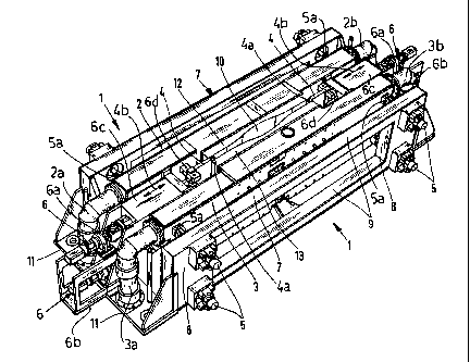
BRIE? DESCRIPTION Ot THE DR]IwING
The above and other objects, features, and advantages
will become more readily apparent from the following description,
reference being made to the accompanying drawing, the sole Figure
of which is a perspective view from above of a spreadable
continuous-casting mold according to the invention.
SPECIFIC DESCRIPTION
The continuous-casting mold shown in the drawing and
mounted as the assembly illustrated upon the lifting mechanism
which is conventionally provided in the continuous-casting line,
can include the mold proper, represented at 10 and formed between
the inwardly facing sides of the mold plates 12 and 13 which are
usually formed of copper or are predominantly formed of copper
and the end faces 4a forming the narrow side walls, of a pair of
members 4 which can extend between the plates 12 and 13 and can
be clamped between them. The adjustment of the members 4 in the
direction of the arrows 4b permits adjustment of the width of the
- 5 -

CA 02253725 2006-08-10
continuous strand emerging from the bottom of the assembly when
the melt is poured into the mold 10 at the top of the assembly.
Two adjustment mechanisms 6 at each end of the mold can
be provided to shift the members 4 and define the strand width.
The mechanism 6 may be screw mechanisms, hydraulic cylinders or
the like. These mechanisms are carried by supports 6a on a pair
of bridge pieces 11 at the ends of the mold via frames 6b. Hence
the reaction force is applied from the frame 6b to the bridge
piece 11. The mechanisms 6a extend through the guide blocks 6c
received between the broad side walls 2 and 3 carrying the copper
plates 12 and 13 to shift the clamps 6d in which the copper
members 4 are removably mounted.
The broad side walls 2 and 3 are cooled in a
conventional manner and for this purpose coolant lines 2a, 2b and
3a, 3b can be provided. The plates 2 and 3 are movable toward
and away from one another and can, upon movement toward and away
form one another, clamp the members 4 between the copper plates
12 and 13 carried by the broad side walls 2 and 3.
According to the invention, the spreadable mold 10 with
its copper plates 12 and 13 carried by the broad side wall is
received within a shape-stable outer frame capable of taking up
the reaction forces of the mold walls 2, 3 and 4 thereon and the
forces generated in clamping, in a closed-force system.
The force-generating means for urging the broad side
walls 2, 3 symmetrically toward one another and toward the center
line of the assembly (and for spreading the members 2 and 3
- 6 -

CA 02253725 1998-12-04
20936
apart) is constituted by four hydraulic cylinders 5 braced
between each broad side wall 2, 3 and a rigid frame 7 juxtaposed
with the broad side walls 2 or 3 along the respective broad side
of the assembly.
Each of the rigid rectangular frames 7 is formed from a
pair of longitudinal bars 9 connected at their ends by transverse
bars 8, the bars all being of rectangular cross section. The
hydraulic cylinders 5 are mounted on the transmission elements 8.
The hydraulic cylinders have piston rods which are articulated at
5a to the respective broad side walls 2, 3.
The broad side rigid frame 8 is connected by the bridge
element 11 previously mentioned to form the shape-stable outer
f rame .
Since the outer frame 1 encompasses the mold 10 on all
sides, all reaction forces which are generated whether they are
thermally created forces (forces produced by thermal expansion)
or adjustment forces are taken up by the closed-force system of
the outer frame. No residual reaction force is transmitted
outwardly. The outer frame 1 so configured that the broad side
walls 2, 3 which carry the copper plates 12 and 13 are always
centered with respect to the center of the assembly and upon
thermal expansion of the broad side walls 2, 3 and the copper
plates 12, 13, these elements all expand symmetrically so that
the forces which must be transmitted to the outer frames from the
broad side walls 2, 3 and the small side walls 4 of the mold are
reduced to a minimum.
- 7 -

CA 02253725 1998-12-04
20936
By providing the adjustment mechanisms for the small
side walls on the bridge elements and in line with one another,
again the forces in opposite directions on the rigid frame are
balanced and play in the system is minimized.
The outer frame and especially the rectangular frame
configuration at the broad side 7 enable electromagnetic coils to
be mounted on the frame so that the assembly can be used as an
electromagnetic brake for the flow of the molten metal through
the mold or an electromagnetic stirrer or agitator for the melt.
The electromagnetic brake or the electromagnetic stirrer can be
inserted from the exterior through the frame between the broad
side walls 2, 3 if desired.
- 8 -

Dessin représentatif
Une figure unique qui représente un dessin illustrant l'invention.
États administratifs

2024-08-01 : Dans le cadre de la transition vers les Brevets de nouvelle génération (BNG), la base de données sur les brevets canadiens (BDBC) contient désormais un Historique d'événement plus détaillé, qui reproduit le Journal des événements de notre nouvelle solution interne.

Veuillez noter que les événements débutant par « Inactive : » se réfèrent à des événements qui ne sont plus utilisés dans notre nouvelle solution interne.

Pour une meilleure compréhension de l'état de la demande ou brevet qui figure sur cette page, la rubrique Mise en garde , et les descriptions de Brevet , Historique d'événement , Taxes périodiques et Historique des paiements devraient être consultées.

Historique d'événement

Description Date
Le délai pour l'annulation est expiré 2016-12-05
Lettre envoyée 2015-12-04
Accordé par délivrance 2008-02-12
Inactive : Page couverture publiée 2008-02-11
Inactive : Taxe finale reçue 2007-10-09
Préoctroi 2007-10-09
Un avis d'acceptation est envoyé 2007-07-10
Lettre envoyée 2007-07-10
Un avis d'acceptation est envoyé 2007-07-10
Inactive : Approuvée aux fins d'acceptation (AFA) 2007-06-11
Modification reçue - modification volontaire 2007-04-20
Inactive : Dem. de l'examinateur par.30(2) Règles 2006-10-20
Modification reçue - modification volontaire 2006-08-10
Inactive : Dem. de l'examinateur par.30(2) Règles 2006-02-20
Lettre envoyée 2003-12-09
Exigences pour une requête d'examen - jugée conforme 2003-11-26
Toutes les exigences pour l'examen - jugée conforme 2003-11-26
Requête d'examen reçue 2003-11-26
Inactive : Page couverture publiée 1999-06-15
Demande publiée (accessible au public) 1999-06-05
Inactive : Transfert individuel 1999-03-08
Inactive : CIB attribuée 1999-01-13
Symbole de classement modifié 1999-01-13
Inactive : CIB en 1re position 1999-01-13
Inactive : Lettre de courtoisie - Preuve 1998-12-24
Inactive : Certificat de dépôt - Sans RE (Anglais) 1998-12-22
Demande reçue - nationale ordinaire 1998-12-22

Historique d'abandonnement

Il n'y a pas d'historique d'abandonnement

Taxes périodiques

Le dernier paiement a été reçu le 2007-12-03

Avis : Si le paiement en totalité n'a pas été reçu au plus tard à la date indiquée, une taxe supplémentaire peut être imposée, soit une des taxes suivantes :

  • taxe de rétablissement ;
  • taxe pour paiement en souffrance ; ou
  • taxe additionnelle pour le renversement d'une péremption réputée.

Les taxes sur les brevets sont ajustées au 1er janvier de chaque année. Les montants ci-dessus sont les montants actuels s'ils sont reçus au plus tard le 31 décembre de l'année en cours.
Veuillez vous référer à la page web des taxes sur les brevets de l'OPIC pour voir tous les montants actuels des taxes.

Titulaires au dossier

Les titulaires actuels et antérieures au dossier sont affichés en ordre alphabétique.

Titulaires actuels au dossier
SMS SCHLOEMANN-SIEMAG AKTIENGESELLSCHAFT
Titulaires antérieures au dossier
JOACHIM SCHWELLENBACH
THOMAS LAMBERTI
Les propriétaires antérieurs qui ne figurent pas dans la liste des « Propriétaires au dossier » apparaîtront dans d'autres documents au dossier.
Documents

Pour visionner les fichiers sélectionnés, entrer le code reCAPTCHA :


Pour visualiser une image, cliquer sur un lien dans la colonne description du document (Temporairement non-disponible). Pour télécharger l'image (les images), cliquer l'une ou plusieurs cases à cocher dans la première colonne et ensuite cliquer sur le bouton "Télécharger sélection en format PDF (archive Zip)" ou le bouton "Télécharger sélection (en un fichier PDF fusionné)".

Liste des documents de brevet publiés et non publiés sur la BDBC .

Si vous avez des difficultés à accéder au contenu, veuillez communiquer avec le Centre de services à la clientèle au 1-866-997-1936, ou envoyer un courriel au Centre de service à la clientèle de l'OPIC.

({010=Tous les documents, 020=Au moment du dépôt, 030=Au moment de la mise à la disponibilité du public, 040=À la délivrance, 050=Examen, 060=Correspondance reçue, 070=Divers, 080=Correspondance envoyée, 090=Paiement})


Description du
Document 
Date
(aaaa-mm-jj) 
Nombre de pages   Taille de l'image (Ko) 
Dessin représentatif 1999-06-14 1 25
Abrégé 1998-12-03 1 14
Description 1998-12-03 8 290
Revendications 1998-12-03 4 97
Dessins 1998-12-03 1 48
Description 2006-08-09 8 288
Revendications 2006-08-09 4 128
Revendications 2007-04-19 2 54
Dessin représentatif 2008-01-22 1 33
Certificat de dépôt (anglais) 1998-12-21 1 163
Courtoisie - Certificat d'enregistrement (document(s) connexe(s)) 1999-04-13 1 117
Rappel de taxe de maintien due 2000-08-06 1 109
Rappel - requête d'examen 2003-08-04 1 113
Accusé de réception de la requête d'examen 2003-12-08 1 188
Avis du commissaire - Demande jugée acceptable 2007-07-09 1 165
Avis concernant la taxe de maintien 2016-01-14 1 170
Correspondance 1998-12-23 1 31
Correspondance 2007-10-08 1 32