Sélection de la langue

Search

Sommaire du brevet 2253873 

Énoncé de désistement de responsabilité concernant l'information provenant de tiers

Une partie des informations de ce site Web a été fournie par des sources externes. Le gouvernement du Canada n'assume aucune responsabilité concernant la précision, l'actualité ou la fiabilité des informations fournies par les sources externes. Les utilisateurs qui désirent employer cette information devraient consulter directement la source des informations. Le contenu fourni par les sources externes n'est pas assujetti aux exigences sur les langues officielles, la protection des renseignements personnels et l'accessibilité.

Disponibilité de l'Abrégé et des Revendications

L'apparition de différences dans le texte et l'image des Revendications et de l'Abrégé dépend du moment auquel le document est publié. Les textes des Revendications et de l'Abrégé sont affichés :

  • lorsque la demande peut être examinée par le public;
  • lorsque le brevet est émis (délivrance).
(12) Demande de brevet: (11) CA 2253873
(54) Titre français: COQUILLE REFROIDIE PAR LIQUIDE
(54) Titre anglais: LIQUID-COOLED CHILL MOLD
Statut: Réputée abandonnée et au-delà du délai pour le rétablissement - en attente de la réponse à l’avis de communication rejetée
Données bibliographiques
(51) Classification internationale des brevets (CIB):
  • B22D 11/04 (2006.01)
  • B22D 11/055 (2006.01)
  • B22D 11/059 (2006.01)
  • B22D 15/00 (2006.01)
(72) Inventeurs :
  • STAGGE, WOLFGANG (Allemagne)
  • HUGENSCHUTT, GERHARD (Allemagne)
  • KEISER, FRANZ (Allemagne)
(73) Titulaires :
  • KM EUROPA METAL AG
(71) Demandeurs :
  • KM EUROPA METAL AG (Allemagne)
(74) Agent: G. RONALD BELL & ASSOCIATES
(74) Co-agent:
(45) Délivré:
(86) Date de dépôt PCT: 1997-05-07
(87) Mise à la disponibilité du public: 1997-11-20
Requête d'examen: 2002-04-18
Licence disponible: S.O.
Cédé au domaine public: S.O.
(25) Langue des documents déposés: Anglais

Traité de coopération en matière de brevets (PCT): Oui
(86) Numéro de la demande PCT: PCT/DE1997/000961
(87) Numéro de publication internationale PCT: DE1997000961
(85) Entrée nationale: 1998-11-06

(30) Données de priorité de la demande:
Numéro de la demande Pays / territoire Date
196 19 073.8 (Allemagne) 1996-05-13
197 16 450.1 (Allemagne) 1997-04-21

Abrégés

Abrégé français

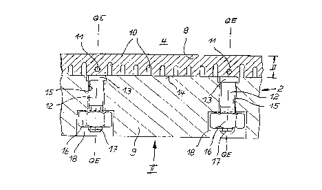
Coquille à refroidissement par un liquide, pour la coulée continue de brames d'acier minces, présentant deux parois latérales larges (2) composées chacune d'une plaque en cuivre (8) et d'une plaque support en acier (9). Les plaques en cuivre (8) délimitant une cavité de moulage (4) sont fixées amovibles sur les plaques supports (9) au moyen de boulons (12) en alliage CuNiMnFe. Les boulons (12) sont soudés aux plaques en cuivre (8) en utilisant complémentairement une bague en nickel (13) comme métal d'apport. Des canaux de refroidissement (10) sont ménagés dans les plaques de cuivre (8), des trous de refroidissement (11) étant par ailleurs prévus dans la zone des plans transversaux (QE) des boulons (12).


Abrégé anglais


A liquid-cooled ingot mould for continuously casting thin steel plates has two
side walls (2) opposite each other, a copper plate (8) and a steel support
plate (9). The copper plates (8) which delimit the mould cavity (4) are
detachably connected to the support plates (9) by metal bolts (12) made of a
CuNiMnFe alloy. The metal bolts (12) are welded to the copper plates (8) using
a nickel ring (13) as welding filler material. Channels for coolant (10) are
provided in the copper plates (8) and cooling bores (11) are provided in the
area of the cross sectional plane (QE) of the metal bolts (12).

Revendications

Note : Les revendications sont présentées dans la langue officielle dans laquelle elles ont été soumises.


Claims
1. Liquid-cooled chill mold for continuous casting of thin steel slabs whose
cross-sectional length is a multiple of the cross-sectional width, having two opposing
wide side walls (2), each with a copper liner (8, 8a) and a backing plate (9, 9a),
and narrow side walls (3) delimiting the width of the slab, with the copper liners (8,
8a) that delimit the mold cavity (4) being detachably attached to the backing plates
(9, 9a) by metal studs (12) made of a CuNiFe alloy and the metal studs (12) being
welded to the copper liners (8, 8a).
2. Chill mold according to Claim 1, characterized in that the metal studs (12) are
made of a CuNi30Mn1Fe material.
3. Chill mold according to Claim 1 or 2, characterized in that the metal studs (12)
are attached to the copper liners (8, 8a) by stud welding methods.
4. Chill mold according to one of Claims 1 through 3, characterized in that themetal studs (12) are welded to the copper liners (8, 8a) using a filler material (13).
5. Chill mold according to Claim 4, characterized in that the filler material (13) is
nickel.
6. Chill mold according to one of Claims 1 through 5, characterized in that thecopper liners (8) of the wide side walls (2) have groove-like coolant channels (10)
running parallel to the direction of casting and covered by the backing plates (9).
7. Chill mold according to one of Claims 1 through 6, characterized in that thecopper liners (8) have cooling holes (11) running parallel to the casting direction
(GR) in addition to the coolant channels (10) and extending in the vertical
cross-sectional planes (QE) of the metal studs (12).
8. Chill mold according to Claim 7, characterized in that the cooling holes (11) are

arranged in the area of the bath level.
9. Chill mold according to one of Claims 1 through 5, characterized in that thebacking plates (9a) have groove-like coolant channels (10a) running parallel to the
casting direction (GR) and covered by the copper liners (8a).
10. Chill mold according to one of Claims 1 through 9, characterized in that thecross section of the mold cavity (4) is larger at the pouring end (5) than at the slab
discharge end (7).
11. Chill mold according to one of Claims 1 through 10, characterized in that the
mold cavity (4) has a multiple conicity.
12. Chill mold according to one of Claims 1 through 11, characterized in that the
mold cavity (4) has at least one flared section (6) at the pouring end (5), tapering
in the casting direction (GR).

Description

Note : Les descriptions sont présentées dans la langue officielle dans laquelle elles ont été soumises.


' CA 022~3873 l998-ll-06
LIQUID-COOLED CHILL MOLD
A liquid-cooled chill mold of the type in question is used for continuous casting
of thin steel slabs whose cross-sectional length is a multiple of its cross-sectional
width. At least each wide side wall is composed of a copper liner bordering the
mold cavity and a steel backing plate. The copper liner is attached to the
backing plate by metal studs projecting laterally. The metal studs therefore pass
through bore holes in the backing plate. At the ends of the bore holes are
enlarged areas where nuts can be screwed onto the threaded ends of the metal
10 studs. With their help the copper liner is tightened against the backing plate.
Within the scope of U.S. Patent No. 3,709,286, it is known that the metal studs
may be made of stainless steel. However, metal studs made of stainless steel
yield poor welded joints with the copper liner because coarse-grained structuresdevelop at the welds, which have a low elasticity and therefore are very sensitive
to flexural stresses.
It is known from the Patent Abstracts of Japan JP-A 3258440 that threaded
bushings can be inserted into rear bore holes in the copper liner bordering the
chill mold space, and longer rods passing laterally through a cooling box can bescrewed into these bushings, and the copper liner tightened against the stainless
steel backing plate. To do so, bore holes are also provided in the backing plate.
In addition, short fastening studs are attached to the rear side of the copper liner
by stud welding. These short fastening studs are provided with bushings into
which the rods passing through the cooling box can be screwed.
Against the background of this related art, the object of the present invention is
to create a liquid-cooled chill mold for high casting rates, in particular for
continuous steel casting in close-to-final dimensions, with a great reduction instrength problems in areas where the metal studs are joined to the copper liners.
This object is achieved according to the present invention with the features of
Claim 1.

CA 022~3873 1998-11-06
At the core of the present invention is the measure of producing the metal studsspecifically of a CuNiFe alloy. Because of such metal studs, in particular hard-drawn metal studs, a considerable increase in strength is achieved with only a
narrow scattering in strength in the welded joints with the copper liner. The latter
may be made of pure copper, e.g., SF-Cu (oxygen-free copper ASTM C12200),
or

- CA 022~3873 1998-11-06
a copper alloy with a high temperature stability, e.g., a hardenable copper alloy
containing chromium and/or zirconium additives. This eliminates the previously
unreliable handling and the many influencing factors during welding which entail100% testing.
In an especially advantageous embodiment according to Claim 2, the metal studs
are made of a CuNi30Mn1Fe material.
To attach the metal studs to the copper liners, the essentially known stud welding
10 method is used to advantage (Claim 3).
To improve the strength and toughness of the welded joint, the metal studs are
welded to the copper liners using a filler material according to Claim 4.
15 Nickel is used in particular as a filler material here (Claim 5). The filler material
may be applied as a thin plate between the metal studs and copper liners. It is
likewise possible to provide the copper liners with filler material at the connecting
points or to plate the end faces of the metal studs. Furthermore, it is possible to
use nickel rings around the periphery of the metal studs as filler material.
According to the features of Claim 6, in another embodiment of the basic idea ofthe present invention, copper liners for the wide side walls have groove-like
coolant channels running parallel to the casting direction and covered by the
backing plates. With the help of such coolant channels, an increased transfer of25 heat from the casting side to the cooling water can be guaranteed, so that high
casting rates can be achieved. Cracking in the copper liners and damage to any
surface coatings that might be present are eliminated. Coolant channels in the
copper liners are used in particular when the copper liner is thick enough to allow
coolant channels with a sufficiently large cross section to be formed.
To also dissipate heat intensively in the area of the metal studs, according to
Claim 7 the copper liners have cooling holes running next to the coolant channels

CA 022~3873 1998-11-06
and parallel to the casting direction, extending in the vertical cross-sectionalplanes of the metal studs. Such cooling holes can be produced by mechanical
drilling. Coolant transferred through these cooling holes prevents a local rise in
temperature in the copper liners around areas where the metal studs are
5 connected to the copper liner in the continuous casting operation.
The cooling bores are preferably arranged in the area of the bath level according
to Claim 8.
10 When using thin copper liners which guarantee a very good heat transfer, the
present invention proposes according to Claim 9 that the backing plates have
groove-like coolant channels running parallel to the casting direction and covered
by the copper liners. Then no coolant channels are provided in the copper liners.
A combination of coolant channels in the copper liners and in the backing plates15 may optionally also be used.
To further increase the casting rate, according to Claim 10 the cross section of the
mold cavity is designed with larger dimensions at the pouring end than at the
outlet end.
In this connection, it is also advantageous according to Claim 11 if the mold cavity
has a multiple conicity.
Finally, according to Claim 12, a flared end tapering in the casting direction may
25 be provided on the pouring end of the mold cavity. This flare serves to
accommodate a submerged tube in particular.
Brief Description of the Drawings
30 The present invention is described in greater detail below on the basis of
embodiments illustrated in the drawings, which show:

CA 022~3873 1998-11-06
Figure 1: a diagram of a vertical longitudinal section through a liquid-cooled chill
mold;
Figure 2: an enlarged partial view of the back side of a copper liner of the chill
5 mold in Figure 1 according to arrow ll in Figure 3;
Figure 3: a partial horizontal section through a wide side wall of the chill mold in
Figure 1 on an enlarged scale; and
10 Figure 4: a partial horizontal section through a wide side wall according to another
embodiment, also on an enlarged scale.
Detailed Description
15 Figure 1 shows a liquid-cooled chill mold 1, which is illustrated only in diagram
form, for continuous casting of thin steel slabs (not shown) whose cross-sectional
length is a multiple of its cross-sectional width. Chill mold 1 has two oppositemultilayer wide side walls 2 and two narrow side walls 3, also opposing one
another, forming mold cavity 4.
On pouring end 5 of mold cavity 4, wide side walls 2 are provided with flared
sections 6 which taper smoothly toward the bottom along part of the height of chill
mold 1. The cross section of mold cavity 4 is rectangular at slab discharge end 7
and is based on the desired cross section of the thin slab. The purpose of the two
25 opposing flared sections 6 is to create space required for a submerged tube (not
shown) for supplying the molten metal.
As Figure 3 also shows, each wide side wall 2 has a copper liner 8 bordering mold
cavity 4 and a steel backing plate 9. Groove-like coolant channels 10, which can30 be supplied with cool water, run parallel to casting direction GR, and are covered
by backing plate 9, are provided in copper liner 8, as also indicated in Figure 2,
which does not show backing plate 8.

~ CA 022~3873 1998-11-06
In addition, Figures 2 and 3 show that cooling holes 11 which can also receive
cooling water run parallel to coolant channels 10. Cooling bores 11 run in vertical
cross-sectional planes QE of metal studs 12 made of CuNi30Mn1Fe, which are
attached to rear side 14 of copper liner 8 by the stud welding method using nickel
rings 13 as filler material. Metal studs 12 pass through bore holes 15 in backing
plate 9. By screwing nuts 16 onto threaded ends 17 of metal studs 12, copper
liner 8 is tightened onto backing plate 9 and secured there. Nuts 16 sit in enlarged
end sections 18 of bore holes 15.
Coolant is supplied to cooling holes 11 through coolant channels 10, expedientlythrough a branch 19 between a cooling hole 11 and adjacent coolant channel 10,
as shown in Figure 2.
Figure 3 also shows that coolant channels 10 next to cross-sectional planes QE of
metal studs 12 are deeper than the other coolant channels 10.
Coolant channels 10 and cooling holes 11 are arranged in a copper liner 8 if
copper liner 8 has a sufficient thickness D.
However, if a thinner copper liner 8a is used, coolant channels 10a are
incorporated into backing plate 9a according to Figure 4 and are covered by
copper liner 8a as copper liner 8a is secured to backing plate 9a with metal studs
12.

Dessin représentatif
Une figure unique qui représente un dessin illustrant l'invention.
États administratifs

2024-08-01 : Dans le cadre de la transition vers les Brevets de nouvelle génération (BNG), la base de données sur les brevets canadiens (BDBC) contient désormais un Historique d'événement plus détaillé, qui reproduit le Journal des événements de notre nouvelle solution interne.

Veuillez noter que les événements débutant par « Inactive : » se réfèrent à des événements qui ne sont plus utilisés dans notre nouvelle solution interne.

Pour une meilleure compréhension de l'état de la demande ou brevet qui figure sur cette page, la rubrique Mise en garde , et les descriptions de Brevet , Historique d'événement , Taxes périodiques et Historique des paiements devraient être consultées.

Historique d'événement

Description Date
Inactive : CIB de MCD 2006-03-12
Demande non rétablie avant l'échéance 2005-05-09
Le délai pour l'annulation est expiré 2005-05-09
Réputée abandonnée - omission de répondre à un avis sur les taxes pour le maintien en état 2004-05-07
Modification reçue - modification volontaire 2002-08-20
Lettre envoyée 2002-05-31
Toutes les exigences pour l'examen - jugée conforme 2002-04-18
Exigences pour une requête d'examen - jugée conforme 2002-04-18
Requête d'examen reçue 2002-04-18
Lettre envoyée 1999-05-19
Modification reçue - modification volontaire 1999-04-01
Inactive : Transfert individuel 1999-04-01
Inactive : CIB attribuée 1999-01-13
Symbole de classement modifié 1999-01-13
Inactive : CIB en 1re position 1999-01-13
Inactive : CIB attribuée 1999-01-13
Inactive : Lettre de courtoisie - Preuve 1999-01-05
Inactive : Notice - Entrée phase nat. - Pas de RE 1998-12-30
Demande reçue - PCT 1998-12-24
Demande publiée (accessible au public) 1997-11-20

Historique d'abandonnement

Date d'abandonnement Raison Date de rétablissement
2004-05-07

Taxes périodiques

Le dernier paiement a été reçu le 2003-04-11

Avis : Si le paiement en totalité n'a pas été reçu au plus tard à la date indiquée, une taxe supplémentaire peut être imposée, soit une des taxes suivantes :

  • taxe de rétablissement ;
  • taxe pour paiement en souffrance ; ou
  • taxe additionnelle pour le renversement d'une péremption réputée.

Les taxes sur les brevets sont ajustées au 1er janvier de chaque année. Les montants ci-dessus sont les montants actuels s'ils sont reçus au plus tard le 31 décembre de l'année en cours.
Veuillez vous référer à la page web des taxes sur les brevets de l'OPIC pour voir tous les montants actuels des taxes.

Historique des taxes

Type de taxes Anniversaire Échéance Date payée
Taxe nationale de base - générale 1998-11-06
Enregistrement d'un document 1999-04-01
TM (demande, 2e anniv.) - générale 02 1999-05-07 1999-04-29
TM (demande, 3e anniv.) - générale 03 2000-05-08 2000-05-02
TM (demande, 4e anniv.) - générale 04 2001-05-07 2001-04-26
Requête d'examen - générale 2002-04-18
TM (demande, 5e anniv.) - générale 05 2002-05-07 2002-05-06
TM (demande, 6e anniv.) - générale 06 2003-05-07 2003-04-11
Titulaires au dossier

Les titulaires actuels et antérieures au dossier sont affichés en ordre alphabétique.

Titulaires actuels au dossier
KM EUROPA METAL AG
Titulaires antérieures au dossier
FRANZ KEISER
GERHARD HUGENSCHUTT
WOLFGANG STAGGE
Les propriétaires antérieurs qui ne figurent pas dans la liste des « Propriétaires au dossier » apparaîtront dans d'autres documents au dossier.
Documents

Pour visionner les fichiers sélectionnés, entrer le code reCAPTCHA :


Pour visualiser une image, cliquer sur un lien dans la colonne description du document. Pour télécharger l'image (les images), cliquer l'une ou plusieurs cases à cocher dans la première colonne et ensuite cliquer sur le bouton "Télécharger sélection en format PDF (archive Zip)" ou le bouton "Télécharger sélection (en un fichier PDF fusionné)".

Liste des documents de brevet publiés et non publiés sur la BDBC .

Si vous avez des difficultés à accéder au contenu, veuillez communiquer avec le Centre de services à la clientèle au 1-866-997-1936, ou envoyer un courriel au Centre de service à la clientèle de l'OPIC.


Description du
Document 
Date
(aaaa-mm-jj) 
Nombre de pages   Taille de l'image (Ko) 
Dessin représentatif 1999-01-18 1 12
Abrégé 1998-11-05 1 60
Description 1998-11-05 6 216
Dessins 1998-11-05 2 59
Revendications 1998-11-05 2 59
Rappel de taxe de maintien due 1999-01-10 1 110
Avis d'entree dans la phase nationale 1998-12-29 1 192
Courtoisie - Certificat d'enregistrement (document(s) connexe(s)) 1999-05-18 1 116
Rappel - requête d'examen 2002-01-07 1 117
Accusé de réception de la requête d'examen 2002-05-30 1 179
Courtoisie - Lettre d'abandon (taxe de maintien en état) 2004-07-04 1 175
PCT 1998-11-05 10 354
Correspondance 1999-01-04 1 30
Taxes 2003-04-10 1 32
Taxes 2002-05-05 1 40
Taxes 2001-04-25 1 45
Taxes 1999-04-28 1 43
Taxes 2000-05-01 1 45