Note : Les descriptions sont présentées dans la langue officielle dans laquelle elles ont été soumises.
CA 02254267 2003-08-25
26474-276D
1
EXPIRATORY FLOW RATE CALCULATOR
This is a divisional application of Canadian
Patent Application 2,097,499 of the Canadian National Entry
of PCT EP92/02271 filed October 2, 1992.
FIELD OF THE INVENTION
The present invention is directed to a method and
an apparatus for determining human peak expiratory flow
rate. More particularly, the present invention is directed
to a method and an apparatus which indicate whether an
asthmatic is functioning at his optimal lung exhalation flow
rate, or deviations therefrom, and the indication therefrom
may be used to initiate remedial actions which have been
recommended for the asthmatic.
BACKGROUND OF THE INVENTION
This invention relates to a method and an
apparatus for determining human peak expiratory flow rate,
to indicate to the asthmatic what course of action to pursue
or what regimen of medication to follow, relative to the
asthmatic's present ventilatory state.
This invention is designed for asthmatics, because
these individuals have a need for determining their current
lung exhalation flow rates and deviations from their own
optimal or peak flow rate. This determination can help
asthmatics decide or follow previously recommended remedial
actions they need to take.
The onset of asthmatic symptoms may occur quickly
or slowly. The faulty subjective assessment of an
asthmatic's own condition by the patient can
CA 02254267 1998-11-09
result in lack of detection of early obstruction of air passageways. If early
obstruction, an early warning
- 1a -
26474-276D
CA 02254267 1998-11-09
-2-
signal, is not detected, the patient will not exercise
measures which stem worsening of the asthmatic episode.
It is to the benefit of those with severe asthma, and
those with mild obstruction to air passage, to be able to
detect early warning signals. Those with severe asthma
may have trouble relying on the more obvious warning
signals which become evident too late, since an asthmatic
episode may result in rapid deterioration of air
exhalation flow rate. Those with mild obstruction to air
passage, too, would benefit by the knowledge that they
are not performing at their peak expiratory flow rate.
Thus, it is important that asthmatics be able to quantify
quickly and accurately the deviations from their normal
peak lung flow rate in order to take appropriate remedial
actions.
This invention can overcome some of the
limitations which exist in the art today. An asthmatic
may have somewhat narrowed airway passages which may not
be detected by a physician using a stethoscope. In
contrast, this invention allows detection of even subtle
changes in air flow rate, giving the individual more
information as to current state. With this system, a
more refined approach is used in asthma management, where
very moderate changes in the asthmatic's state may be
countered with moderate adjustments in remedial actions.
The instrument allows the individual to take
the guesswork out of self-management. The individual may
check for reduced airway flow rate before bedtime, and
ward off the possibility of an attack in the middle of
the night. Thus, this system permits severe attacks to
be warded off by allowing detection of the early warning
signal, low-grade air passage obstruction. There are
other "metering" devices.on the market which indicate the
peak lung exhalation flow of a human, yet these devices
are not part of a system which quantifies the deviation
from optimal peak expiratory flow in an easy and accurate
CA 02254267 1998-11-09
',
_.',
-3-
manner. Use of this system yields information of lung
flow rate deviation for which the user may take the
appropriate remedial measures.
The system effectively acts as a biofeedback
device. With it, the asthmatic learns to recognize
subtle symptoms. In the long run, the asthmatic will
become knowledgeable as to his or her own physiological
state. Thus, the asthmatic will have learned the subtle
signs that indicate mildly reduced peak expiratory flora
rate, and will be able to undertake remedial actions to
reduce the chance of further airflow reduction. Thus,
the system helps achieve an asthmatic's long term goal of
self-vigilance and accurate perception of one's state.
Today's asthmatic and in particular children
may be active individuals. The devices which make up
this system are very compatible with that lifestyle. In
this regard, the peak flow meter itself is small,
lightweight, portable, and reusable. Also, it is
preferably constructed so that children may use or play
with it without damaging it or resetting indicators on
it. That is, the indicators used to indicate the
necessity of remedial action based on the asthmatic's
current expiratory flow rate should beset by a physician
and should not move from the position set by the
physician, despite rugged transport or handling of the
device. The device is characterized by simplicity and
economy of manufacture. A sleeved card which contains
the compiled data is a lightweight, flat device of
dimensions 4"x 8" or less. This may be contrasted with
another airflow metering device available which has a
vertical tower which serves as the meter, attached to a
horizontal cylindrical section into which the user blows.
Such an instrument would not be as convenient as the
present invention for the individual to carry.
From the foregoing, it will be seen that a need
has arisen for a system which integrates use of an
_.
CA 02254267 1998-11-09
-4-
airflow metering device into an asthmatic's active life.
Need is felt for a system which detects subtle and gross
changes in the asthmatic's peak expiratory flow rate, so
that even a mild reduction of such flow rate is promptly
dealt with in a systematic fashion. The present
invention is aimed at providing such a system.
A general object of the invention is to provide
an improved peak flow metering device for use by
asthmatic individuals.
Another object of the invention is to provide a
system to evaluate the current status of an individual
with respect to peak expiratory flow rate and deviations
therefrom.
These and other objects will become more
apparent from the following detailed description and the
appended claims.
gUM~SARY OF THE IN~ENTIOH
In accordance with the present invention, the
asthmatic is provided with the ability to utilize color
zones indicating optimal expiratory flow rate and
deviations therefrom when using a peak flow meter. The
preferred flow meter has a plurality of zones and
settable indicators which define the zones. The setting
of the indicators is preferably done by a physician
(although it could be done by a patient] who uses a
personal zone calculator on which are compiled patient
data relative to peak expiratory flow rate for persons of
given characteristics such as age and size and gender.
The normal or peak expiratory flow rate for a particular
individual is determined by the individual blowing into
the peak flow meter multiple times, resetting the
moveable indicator between puffs. This information, in
conjunction with the predicted peak value revealed on the
personal zone calculator, determines what the
individual's optimal lung exhalation flow rate is. The
CA 02254267 2003-08-25
26474-276D
asthmatic's optimal value thus determined is set usually by
the physician in his office, on the personal zone calculator
to reveal values of a predetermined quantity below the
optimal value, e.g. 10% or 50% below the optimal value.
5 This data is then applied, usually by the physician, to the
peak flow meter, preferably by the physician sliding the
color-coded indicators along a scale to define the three
different color zones. When the color-coded indicators are
set on the peak flow meter, it has been individually
adjusted for the asthmatic to use to determine peak
expiratory flow rate. In one embodiment, the present device
provides high friction color-coded indicators so that after
being set by a physician, the indicators do not vary from
their set position. This prevents the indicators from
sliding during transport or rough handling particularly by
children, which would result in a faulty comparison of the
asthmatic's present condition to optimal conditions.
Subsequent to setting the peak flow meter in this
way, the asthmatic uses it to determine peak expiratory flow
rate. To this end, the asthmatic blows into it and reads in
which zone the moveable indicator has come to rest. If the
moveable indicator comes to rest in a zone which indicates
deviation from optimal expiratory flow rate, the asthmatic
uses the color zone indication to determine what remedial
actions to take. The physician will have instructed the
asthmatic on appropriate remedial actions to take. If the
moveable indicator comes to rest in the zone which indicates
that optimal expiratory flow rate exists, then the user need
not take remedial measures.
3o According to one aspect of the invention of the
present divisional application, there is provided an
CA 02254267 2003-08-25
26474-276D
5a
expiratory flow rate calculator displaying compiled data for
individuals of specified categories which indicates a color-
coded system of indicator zones of expiratory flow rate
which may be set on a peak flow meter comprising, a card,
indicia on the card providing a compilation of data showing
the expiratory flow rate and predetermined deviations
therefrom of individuals having specified characteristics, a
sleeve, a system of color-coded zones on the sleeve showing
data which reveal relative capacities and deviations
therefrom for lung expiration, and means on the card and
sleeve allow them to slide relative to one another, the
sliding of the card revealing several values which are to be
set on the peak flow meter before the user blows air into
the peak flow meter.
BRIEF DESCRIPTION OF THE DRAWINGS
The present invention will be described in
connection with the accompanying drawings, which
CA 02254267 1998-11-09
-6-
illustrate the preferred embodiments of the invention,
and in which:
FIG. 1 is a front elevational view of a peak
flow meter in accordance with the invention;
FIG. 2 is an enlarged elevational view of the
peak flow meter, illustrating the scale and accompanying
indicators;
FIG. 3 is an elevational view of the peak flow
meter, partially broken away:
FIG. 4 is a perspective view of a piston used
in accordance with the invention:
FIG. 5 is a cross-sectional view of the peak
flow meter taken along the line 5-5 of FIG. 3:
FIG. 6 is a cross-sectional view taken along
the line 6-6 in FIG. 3:
FIG. 7 is a perspective view of a zone
calculator in accordance with the invention:
FIG. 8 is an enlarged~elevational view of a
sleeve of the zone calculator in accordance with the
invention:
FIG. 9 is a broken, elevational view of a card
of compiled data of the zone calculator:
FIG. l0 is a series of plots, depicting the
peak flow performance system:
FIG. 11 is a perspective view of a second
embodiment of a peak flow meter embodying various
features of the present invention:
FIG. 12 is a plan view of the peak flow meter
of FIG. 11:
FIG. 13 is a cross-sectional view of the peak
flow meter of FIG. 11 taken along line 13-13 of FIG. 11:
FIG. 14 is an enlarged, partial cross-sectional
view of the spring mechanism of the peak flow meter of
FIG. 11, taken along line 14-14 of FIG. 13:
CA 02254267 1998-11-09
1
_7_
FIG. 15 is an enlarged perspective view of the
spring and disc arrangement of the peak flow meter of
FIG. 11;
FIG. 16 is an enlarged cross-sectional view of
the peak flow meter of FIG. 11 taken along line 16-16 of
FIG. 12:
FIG. 17 is an enlarged perspective view of the
moveable indicator of the peak flow meter of FIG. 11,
showing the Z-shaped friction engaging portion employed
to prevent unintentional sliding of the indicator; and
FIG. 18 is a perspective view of the peak flow
meter of FIG. 11, shown with the color-coded indicators
being set by a physician using a writing implement.
DETAILED DESCRIPTION OF THE INQENTION
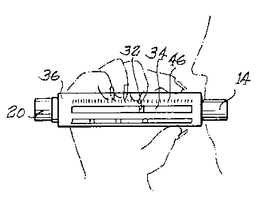
Now, referring to the drawings, a first
embodiment of the peak flow meter of the invention is
generally shown in FIG. 1. In this embodiment, the peak
flow meter is a lightweight instrument having a body 36
of which can be held in the hand while an air inlet 14 is
placed in the mouth of the user. The body 36 is
preferably formed of aluminum, such as by extrusion, to
provide a rugged and durable device. A moveable
indicator 32 slides along a slit 34 in response to the
user blowing air in through the air inlet 14 and air
exhausts through the body at an air outlet 20. Once an
individual knows his optimal expiratory flow rate, the
individual can evaluate whether he is functioning at
optimal expiratory flow rate by using the peak flow
meter.
The present invention provides the asthmatic
with information regarding subtle and gross changes in
his peak expiratory flow rate. The present invention
comprises a method for determining flow rate for air
exhalation by the lungs using a peak flow meter 36. An
individual's peak expiratory flow rate is determined.
CA 02254267 1998-11-09
_g_
Using that information, predicted expiratory values are
determined and applied in the form of zone settings
defined by zone indicators 38, 40 and 42 on the peak flow
meter. A zone calculator may also be provided to the
asthmatic to set his own zones but it is preferred that
the physician and not the patient be given the personal
zone calculator 36. Alternatively, the physician may
consult his own tables or charts to define the zones.
The peak flow meter is then ready for use. The
individual concerned about his current expiratory flow
rate may blow into the peak flow meter and read what his
current color zone is. The color zone indicates to the
asthmatic individual whether remedial action need be
taken. Preferably, the zones are color-coded although
they need not be color-coded. For example, the zones
could be coded numerically as zones l, 2 and 3: or
alphabetically as zones A, B and C; or by words such as
"peak", "ten percent" and "fifty percent". The number of
zones and their extent may also be varied from that
described herein.
Turning now in greater detail to the first.
embodiment illustrated in FIG. 2, it will be seen that
this figure is a more detailed representation of the peak
flow meter shown in FIG. 1. The body 36 of the peak flow
meter in FIG. 2 is visible, as are the elements on the
face side of the apparatus. Most obvious is non-linear
scale 46 oriented alongside the slit 34. The air outlet
through which air exhausts is_visible at 20. The
moveable indicator 32 moves in the slit 34. Three color
zone indicators 38, 40, and 42 move in a track 44. The
color zone indicators 38, 40, and 42 are set at the
positions along the scale 46 that correspond to the
values preferably obtained by using the compiled data on
a personal zone calculator which is represented in FIG.
7. Alternatively, a physician may consult other texts
and data to set the zones. The mounting of the indicator
~, CA 02254267 1998-11-09
.-
_g_
32 and the color zone indicators 38, 40 and 42 for
sliding movement is described further below in connection
with the alternative embodiment of the invention. The
indicator which corresponds to the peak expiratory flow
rate 38 is green. The indicator which corresponds to 10%
below the peak expiratory flow rate 40 is yellow. The
indicator which corresponds to 50% below the peak
expiratory flow rate 42 is red. Other colors may be
used. The preferred zone calculator is in the form of a
slide chart or slide rule but manifestly the calculations
made could be done using an electronic computer chip or
calculator.
As represented by FIG. 2, the peak flow meter
36 is used in cooperation with the personal zone
calculator 49 which is represented by FIG. 7. Focusing
on FIG. 2, the settings for the three color zone
indicators 38, 40, 42 are obtained by reading the
personal zone calculator 49 (FIG. 7) and are moved in the
track 44 to the appropriate settings. Before using the
peak flow meter to identify diminished expiratory flow
rate, the user must determine what is his optimal
expiratory flow rate. To do this, the moveable indicator
32 (FIG. 2) is set at the lowest point in the slit,
corresponding to zero on the non-linear scale 46. The
user then places the air inlet 14 to his lips and blows
air into the peak flow meter. The air blown through the
body of the peak flow meter 36 pushes the moveable
indicator 32 along the slit 3.4 to a position where it
comes to rest and stops there. The position of the
indicator on the non-linear scale 46 which is oriented
alongside the slit 34 can be read. The user observes the
value on the scale at which the indicator comes to rest,
and repeats the process two times. The highest of these
values indicates to the physician the user's individual
peak expiratory flow rate.
CA 02254267 1998-11-09
-10-
The physician or the user then consults the
personal zone calculator 49 (FIG. 7) to compare the
user's individual peak expiratory flow rate with the
average predicted value based on age, height, and sex
which is presented in the compiled medical research
presented on the personal zone calculator 49. A card 50
is slid through a sleeve 92. On the card 50 are compiled
medical research which are visible through windows 94,
96, 98 in the sleeve 92. As the card 50 is slid through
the sleeve 92, different data are revealed through the
windows 94, 96, 98. A mare detailed depiction of the
sleeve 92 of the personal zone calculator is shown in
FIG. 8. It can be seen that on the sleeve 92 adjacent to
the windows are printed indicators for the windows.
Alongside a window 102 are scales of age in years for
both males 104 and females 106. Visible through the
window 102 are varying heights of individuals. To use
the personal zone calculator, the asthmatic slides the
card through the sleeve until his height, visible on the
card through window 102 lines up with the correct age on
the scale 104 (in this case, for males). Once this is
done, the values corresponding to the predicted
expiratory flow rate and the deviations from predicted
lung expiratory flow rate are visible through the windows
94, 96, 98. Adjacent to each of the windows 94, 96, 98
is indicated one of the color zones. The color green is
adjacent to window 98 and yellow is adjacent to window
96. Adjacent to window 94 is. the corresponding color
red. Adjacent to the windows 94, 96, 98 are arrows which
point into the windows. The value beneath the arrow that
is visible through window 98 corresponds to the predicted
value of expiratory flow rate for individuals of that
age, height, and sex. Similarly, the value beneath the
arrow visible through window 96 corresponds to another
value, for example, 10% below the predicted value as
indicated on the sleeve. In a similar fashion, the value
CA 02254267 1998-11-09
-11-
beneath the arrow visible through window 94 corresponds
to a still further value, for example, 50% below the
predicted value of peak expiratory flow rate for
individuals of that age, height, and sex. These first
and second values of 10% and 50% are merely exemplary,
and the physician may deviate therefrom.
The physician or user compares the highest
value achieved by blowing into the peak flow meter with
the value that is the predicted peak expiratory flow rate
for individuals of that age, height and sex. If the
highest number achieved by blowing into the peak flow
meter is much less than the physician's desired flow
rate, the physician may prescribe further remedial
actions. If the highest number achieved by blowing into
the peak flow meter is visible in the window 98, or is
higher than the values visible in the window, then this
value is the individual's optimal expiratory flow rate.
Once the individual's optimal expiratory flow rate is
determined, the physician will set the personal zone
calculator so that the user's optimal value is set
beneath the arrow in window 98 so that the individual's
sub-optimal lung capacities can be read through windows
94 and 96. At this point all three values may be applied
to the peak flow meter (FIG. 2) by sliding the colored
indicators 38, 40, 42 along the track 44 to the
appropriate values on the non-linear scale 46. The
optimal peak expiratory flow rate is set on the green
indicator 38. A first value, for example, 10% below
optimal expiratory flow rate, is set on the yellow
indicator 40. A second value, for example, 50% below
optimal expiratory flow rate, is set on the red indicator
42. High friction between the colored indicators and the
body of the apparatus prevents the colored indicators
from inadvertently sliding from the position set by a
physician.
CA 02254267 1998-11-09
r~ y
-12-
For this asthmatic, the physician has now set
individualized values on the peak flow meter. The meter
is ready to be used by that individual to detect possible
reduction in airflow. To do this, the asthmatic checks
to be sure that the colored indicators (FIG. 2) 38, 40,
42 are in the proper positions along the scale 46. In
this regard, the settings of the colored indicators as
established by the physician using the personal zone
calculator are recorded in a log for the patient to
retain so that should the colored indicators move from
their set position, the patient can then reset the
indicator to its proper position. For instance, if a
child moves the colored indicators, his parent can reset
the indicators by consulting the log.
The user then blows as hard as he can into the
peak flow meter and reads the color zone that corresponds
to his present expiratory flow rate. If the moveable
indicator 32 comes to rest higher on the scale than the
green indicator or between the green indicator 38 and the
yellow indicator 40, then the user is said to have
optimal expiratory flow rate, and is in the green zone.
If the moveable indicator 32 comes to rest at the yellow
indicator 40 or between the yellow indicator 40 and the
red indicator 42, then the user is said to have 10% below
optimal expiratory flow rate, and is in the yellow zone.
If the moveable indicator 32 comes to rest at or below
the red indicator 42 then the user has 50% below optimal
expiratory flow rate, and is in the red zone. With such
information, the user can take remedial actions if his
expiratory flow rate is in the yellow or red zones. The
physician will have explained to the user, and/or to his
parent, if the user is a child, the appropriate remedial
measures to take.
Turning in more detail to the functioning of
the peak flow meter, FIG. 3 is a depiction of the peak
flow meter of the first embodiment which is partially
CA 02254267 1998-11-09
-13-
broken away. The air inlet 14 is visible, as is the end
20 through which air exhausts. A disc which corresponds
to the air inlet 14 is shown in cross-section at 49.
FIG. 5 also represents the air inlet disc 49. FIG. 5 is
an end-on view of the disc which is shown in cross-
section in FIG. 3 at 49. An end means through which air
exhausts 75, FIG. 3, is also seen in an end-on view in
FIG. 6. Visible in FIG. 3 is a centrally located,
axially extending slide bar 52. This bar extends the
length of the peak flow meter, attaching at either end to
the end discs represented by 49 and 75. This bar
supports a piston 54 which travels along the bar. Air
blown in through the air inlet 14 pushes the piston to
slide along the slide bar as indicated by the hatched
piston 54. The piston 54 pushes to compress a constant
rate spring 55 which resists the piston 54 travel and
expands to return the piston once the air pressure of
exhalation ceases. The spring 55 is shown only
diagrammatically in FIG. 3. A spring arrangement is
described in greater detail for the embodiment of FIGS.
11-18 in which the spring is a coiled tension spring
which is elongated under the influence of the piston 54,
as will be described further below. The piston 54 pushes
against the moveable indicator 32. When airflow ceases,
the piston 54 returns to the starting point, leaving the
indicator at the maximal point of airflow. The piston
merely abuts the indicator 32 when the indicator 32 is
manually slid to its initial starting point against the
piston. The piston separates from the indicator 32 when
its returned by the spring. This indicates the
individual's current peak expiratory flow rate, which is
readable on the scale 46, and the individual's current
expiratory flow rate is determined by reading in which
color zone the indicator stopped. The scale 46 is non-
linear and the constant rate spring accommodates use of a
single instrument by both adults and children.
CA 02254267 1998-11-09
-14-
The piston 54 is shown in more detail in FIG.
4. It consists of a cylindrical portion 61 having a bore
63 through which the axial slide bar extends, and a flat
disc-like portion 62 which blocks the flow of air and is
pushed along by the air when the user exhales into the
peak flow meter. The spring is connected to the disc 62.
The shape of the disc-like portion is made to fit within
the hollow cylinder of the peak flow meter, in the
preferred embodiment it has a flattened edge 64 to slide
along the flat front face portion 65 (FIG. 2) of the body
36. Alternatively, the shape of the disc-like portion 62
could be round to fit within a round body of the peak
flow meter. Another embodiment of the disc-like portion
would be square fitting within a square body of the peak
flow meter. The purpose of the disc is to allow the
piston to respond to the forced air as the asthmatic
blows into the peak flow meter.
FIG. 5 is a cross-sectional view of the air
inlet. It can be seen in the preferred embodiment that
the air inlet 49 comprises a molded, plastic cylindrical
wall 67 having three radially, inwardly extending areas 68
which support a small central hub 66. The hub 66 has an
inwardly facing seat 69 (FIG. 5) to receive and support
one end of the slide bar 52. Between the support arms
are three sector shaped passages 71 through which air
flows from the inlet into a hollow tubular chamber 73 in
the body 36 of the peak flow meter.
The other end of the peak flow meter body
supports the slide bar 52 and is vented to permit air
exhaust from the body chamber 73. Herein, the venting is
achieved through a series of vent openings 72 of circular
shape in a molded end wall 75. The end wall has a
central seat hub 77 into which is seated an end of the
slide bar 52.
Both of the end discs 49 and 75 are integral
with the body 36 of the peak flow meter, remaining
CA 02254267 1998-11-09
'.
-15-
attached thereto throughout usage. To Wash the
apparatus, the entire peak flow meter apparatus is simply
inserted into a dishwasher or washed manually, and there
is no need to remove the end discs 49 and 75 to
thoroughly wash the apparatus. Furthermore, not only are
the end discs 49 and 75 not separable from the remainder
of the apparatus, but no other parts are separable
either. Thus, the apparatus can be safely used by
children without concern the small parts will be
swallowed.
Turning to the preferred embodiment of the
personal zone calculator (FIG. 7), it can be seen that
there are two moveable means to this portion of the
invention. The card 50 is sized to closely fit and to
slip inside the sleeve 92. In the preferred embodiment
of the card FIG. 9, there is a row of data corresponding
to individual person's heights 80, and rows of medical
data relating to predicted expiratory flow rates for
individuals of a particular category 82, 84, 86. The
numbers are oriented increasing from left to right.
A more detailed view of the sleeve 92 is shown
in FIG. 8. The preferred embodiment of the sleeve was
described above in reference to the functioning of the
personal zone calculator in cooperation with the peak
flow meter. The sleeve has four rectangular windows
(FIG. 8) 94, 96, 98, 102. Adjacent to window 102 are
aligned scales of age in years for both males 104 and
females 106. Visible through window 102 is a scale of
individual's heights. The user lines his height up under
his age on scale 104, and reveals in the windows below,
94, 96, 98 the average values of expiratory flow rate and
deviations therefrom. Window 98 is the green window, and
the value which is revealed through that window by the
arrow pointing into the window is the predicted value of
expiratory flow rate for an individual of a certain age,
sex and height. Window 96 is the yellow window, and the
CA 02254267 1998-11-09
-16-
value which is revealed by the arrow which points into
that window is 10% below the predicted expiratory flow
rate for such an individual. Window 94 is the red window
and the value which is revealed by the arrow which points
into that window is 50% below the predicted expiratory
flow rate for such an individual.
The preferred embodiment of the personal zone
calculator is that illustrated in FIGS. 7 and 8, but it
has other forms. Another form of this part of the
l0 invention would be a wheel form, in which windows on a
disc reveal compiled medical data presented on another
disc which is visible through the windows. Such discs
could be spun in relation to one another, so that
different data are revealed in different orientations.
Another embodiment of the peak flow meter of
the present invention is illustrated in FIGS. 11-18. The
peak flow meter includes a body 136 comprised of a
generally cylindrical, piston housing portion 136b and an
indicator housing portion 136a which is securely attached
to the piston housing portion 136b by rivets 139, as best
seen in FIG. 13. The rugged construction includes a
sturdy aluminum body 136 and indicators that can be put
into a dishwasher for cleaning and which will withstand
abuse by a child.
With further reference to the cross-sectional
view of FIG. 13, the peak flow meter of this embodiment
employs a tension spring 155 in contrast with the
compression spring 55 seen in~FIG. 3. That is, in this
embodiment, the spring 155 is extended as the piston 154
advances in response to breath exhalation, rather than
being compressed as in the embodiment of FIGS. 1-6.
The arrangement of the spring mechanism of this
embodiment is further illustrated in FIGS. 14 and 15. As
with the previous embodiment, the slide bar 152 extends
from the inlet end 114 to the outlet end 120 of the flow
meter and includes a reduced end 153 which is received in
CA 02254267 1998-11-09
..._.1 1
-17-
inwardly facing seat 169, and opposite reduced end 151
which is received in central seat hub 177. The piston
154 is slidable on the slide bar 152 and moves in
response to, and in proportion to, the force of breath
exhalation. The spring 155 is a coil spring which
includes a mounting end 156 of reduced diameter, which
end 156 is received and secured in the inwardly facing
seat 169. The opposite end of the spring 155 includes an
extending portion 157 which is fixedly secured within
aperture 159 of the piston 154.
Thus, when a user exhales into the inlet 114 of
the apparatus, the piston 154 is pushed away from the
user and the spring 155 is extended as illustrated in
phantom in FIG. 13.
The piston merely abuts the indicator 132 when
the indicator is at its starting position and separates
from the indicator when the piston is being pulled in the
return direction by the spring 155. Subsequently, at the
termination of exhalation, the spring returns to its
contracted position indicated by solid lines in FIG. 13.
With reference to FIGS. 16-18, the sliding
indicator 132 and the color-coded indicators 138, 140 and
142 are shown. The sliding indicator 132 includes a an
inwardly projecting stem 160 which is received within
elongated channel 162 in the aluminum body 136 to be
engaged by the piston 154 as the piston is advanced to
move the sliding indicator 132 to its peak position. As
seen in FIG. 17, in this embodiment the sliding indicator
also includes a Z-shaped base 164 which resides within
the widened portion of T-shaped channel 166, and has an
indicating arrow 168 mounted thereto Which resides in the
narrower portion of the T-shaped channel 166. This
compression spring is made of plastic which is thin and
flexible and is bent at fold lines 164a and 164b with an
upper ply 164c, an oblique ply 164d and a bottom ply
164e. The plies 164a and 164e are compressed by the top
CA 02254267 1998-11-09
-18-
and bottom sides 166a and 166b of the channel 166. This
compressed spring provides frictional engagement between
the sliding indicator 132 and the body 136 so that the
sliding indicator 132 remains stationary after being
moved to its peak position, despite retraction of the
piston 154 and/or tilting of the body 136 of the
apparatus following exhalation. This is important to
prevent erroneous peak flow readings. The Z-shaped base
164 should, accordingly, be proportioned in relation to
the channel 166 and made of a material that provides
sufficient frictional engagement to prevent inadvertent
sliding of the indicator 132, yet still allow the
indicator 132 to slide easily when pushed by the piston
154 during exhalation.
In contrast, the three color-coded indicators
138, 140 and 142 reside and slide within T-shaped channel
180 (FIG. 16) with significantly greater frictional
engagement. The illustrated indicators are small block
shaped elements which have a wider bottom portion 181
captured in a wider bottom portion 180a of the T-shaped
channel 180. The indicator elements may be formed of
rubber or other material having a high coefficient of
friction and mounted in the channel so that considerable
force is needed to reset them. Since the color-coded
indicators 138, 140 and 142 are preferably set by a
physician and are generally not moved between consecutive
uses of the peak flow meter, except when re-set by the
physician, the frictional engagement should be sufficient
to prevent inadvertent sliding or movement of the
indicators during transport or handling, or during
tampering by a child. It has been found that these
characteristics are provided by making the color-coded
indicators 138, 140 and 142 of rubber. To further
prevent inadvertent sliding of the- color-coded indicators
138, 140 and 142, the indicators may be situated
completely below the surface 137 of the body 136. This
CA 02254267 1998-11-09
I
-19-
prevents the color-coded indicators from sliding when
brushed against, yet still allows easy movement of the
indicators when pushed with an instrument narrow enough
to fit within the channel 180.. By way of example, FZG.
18 depicts the color-coded indicators being repositioned
with use of a common pen 182.
From the foregoing, it will be seen that there
has been provided a convenient method for determining
human expiratory flow rates, to indicate to the asthmatic
what remedial actions to take in case of subtle or gross
changes in expiratory flow rate.