Note : Les descriptions sont présentées dans la langue officielle dans laquelle elles ont été soumises.
CA 02254691 1998-11-25
1
TITLE OF THE INVENTION
TILE TRACING APPARATUS AND METHOD
FIELD OF THE INVENTION
The present invention relates to tiles. More specifically,
the present invention is concerned with a tile tracing apparatus and with
a tile tracing method to reproduce, on a tile, lines representative of the
layout of the floor where the tile is to be installed.
BACKGROUND OF THE INVENTION
Persons installing tiles on a floor are regularly
challenged with the cutting of particular tiles to conform to the floor layout
where the particular tile has to be installed.
The commonly accepted method used for cutting such
tiles consists in taking manual measurements of the floor layout in the
area where the tile is to be installed. These measurements are then
transferred to a conventional tile, which is thus ready to be cut.
Of course, the method used to cut the tile varies with the
type of tile used. For example, knives may be used to cut vinyl tiles while
specially designed cutting assemblies are used to cut through encaustic
and ceramic tiles.
CA 02254691 1998-11-25
2
The precision required to cut tiles is usually not of great
importance since a quarter-round molding is usually installed over the
tiles at the floor to wall joint. However, the manual measurement and the
transfer of these measurements onto a tile often lead to the waste of a tile
which has been improperly cut, which increases the overall cost of the
floor covering.
Furthermore, the time required to take the
measurements and to transfer these measurements onto the tile is
usually quite long, which is another drawback of the manual
measurement taking method.
OBJECTS OF THE INVENTION
An object of the present invention is therefore to provide
a tile marking apparatus and a method therefor.
Another object of the invention is to provide a tile
marking apparatus that is designed to transfer, directly onto a tile, the
layout of the floor where the tile is to be installed, for most floor layouts.
Other objects, advantages and features of the present
invention will become more apparent upon reading of the following non
restrictive description of preferred embodiments thereof, given by way of
example only with reference to the accompanying drawings.
CA 02254691 1998-11-25
3
BRIEF DESCRIPTION OF THE DRAWINGS
In the appended drawings:
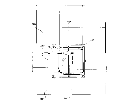
Figure 1 is a top plan view of a tile marking apparatus
according to an embodiment of the present invention;
Figure 2 is a sectional view taken along line 2-2 of
Figure 1;
Figure 3 is a top plan view of the tile marking apparatus
of Figure 1 illustrated in operation onto a vinyl tile; and
Figure 4 is a sectional view taken along line 4-4 of
Figure 1.
DESCRIPTION OF THE PREFERRED EMBODIMENT
Turning now to Figures 1 and 2 of the appended
drawings, a tile marking apparatus 10 according to a preferred
embodiment of the present invention will be described.
The tile marking apparatus 10 includes a frame
assembly 12, a longitudinally movable assembly 14 mounted to the frame
assembly 12 and a laterally movable marking assembly 16 mounted to
the longitudinally movable assembly.
CA 02254691 1998-11-25
4
The frame assembly 12 includes a generally rectangular
base 18 having internal dimensions configured and sized to receive a
conventional tile having predetermined dimensions, and a pair of lateral
guides 20, 22.
The generally rectangular base 18 includes an aperture
24 having four right angle corners 26, 28, 30 and 32, and four cutout
portions 34, 36, 38 and 40, and a handle 42. As can be better seen from
Figure 2, the sides of the aperture 24 define sloping surfaces, for example
44. These surfaces are provided with dimension markings 45.
Each right angle corner 26, 28, 30 and 32 is provided
with a respective semi-circular cutout portion 27, 29, 31 and 33 facilitating
the precise positioning of the apparatus 10 onto a tile to be marked.
As will be described hereinafter, the dimensions of the
square figure defined by the internal edges of the right angle corners 26,
28, 30 and 32 is advantageously generally similar to the dimensions of a
tile to be marked by the apparatus 10.
The lateral guide 20 includes a cylindrical sliding rod 46
and a pair of rod mounting elements 48, 50 mounting the rod 46 to the
base 18. Similarly, the lateral guide 22 includes a cylindrical sliding rod
52 and a pair of rod mounting elements 54, 56 mounting the rod 52 to the
base 18.
The longitudinally movable assembly 14 includes first
and second movable elements 58, 60 each including a central aperture
CA 02254691 1998-11-25
(not shown) allowing the elements 58, 60 to be slidably mounted to
respective cylindrical sliding rod 46 and 52 through ball bearings (not
shown) or other friction reducing material (not shown).
5 The longitudinally movable assembly 14 also includes
a transversal cylindrical rod 62 provided with a first end 64 mounted in an
aperture of the movable element 58 and a second end 66 mounted in an
aperture of the movable element 60.
The laterally movable assembly 16 includes a movable
carriage 68 and a contour following rod 70 having a proximate end 72
provided with a pen attachment device 74, to which a pen 76 may be
mounted, and a distal end 78 provided with a contour following tip 80.
As will be further described hereinbelow, the distance
separating the tip 80 and the point 82 (see Figure 2) of the pen 76 is
essentially the dimension of the side of a tile to be marked by the
apparatus 10.
The movable carriage 68 includes a lateral aperture (not
shown) allowing the carriage 68 to be slidably mounted to the cylindrical
rod 62 through ball bearings (not shown).
The movable carriage 68 further includes a longitudinal
aperture (not shown) to receive the contour following rod 70 therein. The
contour following rod 70 is maintained in a fixed relationship with the
carriage 68 through a securing element 84.
CA 02254691 1998-11-25
6
Turning now to Figures 3 and 4 of the appended
drawings, the operation of the tile marking apparatus 10 will be described.
In the following description of the operation of the invention, the term
"marked tile" is intended to define the tile being marked by the apparatus
10 and the term "adjacent tile" is intended to define the tile adjacent to the
marked tile, where the apparatus 10 is positioned.
In the example of use illustrated in Figures 3 and 4, a
door frame 200 is so positioned that a specially cut tile provided with an
adequate cutout must be installed.
To operate the apparatus 10 to mark a tile for
subsequent installation, the user simply has to execute the following
steps:
1- conventionally installing the tiles adjacent to the
position where a specially cut tile must be installed (in the example of
Figures 3 and 4, these are tiles 202, 204, 206, 208 and the adjacent tile
208 shown in Figure 4);
2- positioning a tile, the marked tile 212, in an
overlapping relationship with the adjacent tile 210;
3- positioning the apparatus 10 in an overlapping
relationship with the marked tile 212 so that the corners of the tile 212 are
registered with the right angle corners 26, 28, 30 and 32; and
CA 02254691 1998-11-25
7
4- following the contour of the door frame 200 with the
contour following tip 80.
The above steps defining a method for making tiles for
subsequent cutting.
The contour of the door frame 200 is therefore partially
reproduced onto the marked tile 212. The user then simply has to
manually finish the lines (see for example the dashed-dotted line 214 of
Figure 3) that the pen could not mark onto the tile 212 since the contour
following tip 80 could not follow the corresponding contour line of the door
frame 200. It is however to be noted that to manually mark these lines,
the user does not have to take measurements.
When all the lines are properly marked onto the marked
tile 212, the user may cut the tile along these lines and install the tile 212
at its intended position in a conventional manner.
It is to be noted that the undersurface of the base 18
could be made of a friction increasing material to prevent apparatus
motions while in use.
It is also to be noted that the pen 76 could be replaced
by a hard pointed tip to engrave the lines instead of marking them.
It is to be noted that the example of Figures 3 and 4
relates to the marking and the cutting of a vinyl or similar tile. For tiles
that are usually installed with a joint separating adjacent tiles, for example
CA 02254691 1998-11-25
ceramic tiles separated by a mortar joint, the distance between the
contour following tip 80 and the tip 82 of the pen 76 would be the
dimension of a side of the tile plus the width of the mortar joint. Also, if
an apparatus similar to the apparatus 10 is designed to trace onto tiles
that are usually installed with a joint separating adjacent tiles, the base 18
could advantageously be provided with downwardly extending pointed
feet (not shown) preventing the underside of the base 18 from contacting
the mortar joints and becoming soiled.
Although the present invention has been described
hereinabove by way of preferred embodiments thereof, it can be modified,
without departing from the spirit and nature of the subject invention as
defined in the appended claims.