Note : Les descriptions sont présentées dans la langue officielle dans laquelle elles ont été soumises.
CA 02254705 2000-12-22
BACKGROUND OF THE INVENTION
In most commercial, industrial and institutional buildings, including schools,
hospitals, hotels and similar type structures, double doors hung in metal
frames are
used. In many cases these doors are latched to a center post, caned a mullion,
that
allow use of single doors in double door frames. In many instances the mullion
is a
movable hollow core mullion and can be removed to allow for large loads to be
passed through the doors and then reinstalled. The mullion post holding
systems
currently m use employ sliding wedges, hold-down clips, wrap around brackets
among other types of hold down devices and are attached with various kinds of
screws or bolts to fittings in the floor and top of the door frame. These
become worn,
rusted, clogged with dirt and grime and generally deteriorate with use and age
and are
invariably painted over. It is with the removal and reinstallation of such
mullions that
problems occur thereby making it a time consuming job, requiring special tools
and
other measures to remove and replace the mullion.
PRIOR ART
Various attempts have been made to overcome the problems associated with
removing and reinstalling movable mullions. Movable mullions that do not
require
screwing and bolting are known.
United States Patent 2,275,730 issued on March 10, 1942 to Casse discloses a
removable mullion which is designed for overhead doors, and is held in place
by a
spring type clamp or latch to hold the mullion in place and allow for its
removal and
attachment.
United States Patent 3,000.062 issued on September 19. 1961 to McCandless
discloses a mullion that is held in place by the use of pressure applied to
the mullion
during installation, and release upon removal.
United States Patent 3.319,382 issued on May 16, 1967 to Hand shows a
mullion unit that is forced over a base plate and held by friction, and is
slid into an
upper joint by additional friction and held in place by a screw type unit. The
method
of fixing the mullion in place is only broadly defined in this description.
CA 02254705 2000-12-22
United States Patent 5,435,102 issued on July 25, 1995 to McCarthy shows a
mullion fastened to a base unit and hinged to allow its tilting into a
horizontal position
after it is released at the top of the doorway. The unit also allows for the
complete
removal of the mullion. The fastening device in this unit is a key operated
lock.
United States Patent 5,450.697 issued on September 19, 1995 to Prucinsky is
very similar to the McCarthy patent, assigned to the same assignee, which
extends the
McCarthy patent by using key operated locks at either end of the mullion for
easier
removal, as well as disclosing different base and top attachment units.
In both United States patents 5,435,102 and 5,450,607 which represent the
most recent state of the art, devices that employ a keyed cylinder with a cam
to
actuate a plunger or mortise dead bolt are used. The key cylinder is a
delicate
mechanism depending on small sensitive springs and pins that are susceptible
to
moisture, freeze up, corrosion or heat. At the most crucial times during
emergencies
these systems can fail after lengthy non use and especially it the key can not
be found
readily.
Although these patents address the problem of providing removable mullions.
they have many disadvantages as will become apparent hereinafter. Furthermore,
none of them show the simple, durable, easy to use and maintain, inexpensive
mullion
latch of this invention which is friendly to the user and allows for easy and
rapid
removal and reinstallation of removable mullions, while at the same time
providing a
safe and secure system. My Canadian application for patent SN 2,207,535 filed
June
11. 1997 and laid open to inspection on December 19, 1997 and describes and
claims
a mullion latch that may be removed and installed without tools.
SUMMARY OF THE INVENTION
This invention seeks to provide a mullion latch that enables the rapid removal
and reinstallation of a hollow mullion post that is simple, durable, easy to
use,
inexpensive, economical to make and easy to maintain and which is friendly to
the
user and is secure and vandal resistant.
2
CA 02254705 2000-12-22
This invention seeks to provide a mullion latch for use at the top of the
mullion post that is secure and tamper proof and allows for simple tools, such
as a rod
or even the shaft of a screwdriver, or other common tool such as the handle of
a
pliers, for the removal of the mullion post, and still allow for
reinstallation by one
person without the use of any tools. It is a primary object of this invention
to provide
a security system of a mullion latch and post without sacrificing safety which
is
durable and functions in a fail safe manner after repeated usage.
Still further this invention seeks to provide a secured mullion latch which
may
be adapted for use in combination with a variety of mullion shapes that are
employed
in double door mullion assemblies.
This invention seeks to provide adapters for use with the mullion latch of
this
invention with the variety of hollow core mullion shapes in use in double door
mullion assemblies.
This invention also seeks to provide an assembly kit for retrofitting or
adapting existing mullions to be readily removable and reinstallable which
includes
the mullion latch of this invention combined with an adapter for use with a
variety of
hollow mullion shapes and a disengaging tool.
Still further this invention seeks to provide a mullion latch which is easy to
operate under any conditions day or night, that does not have to be touched
during
reinstallation of the mullion post and which one person can handle in either
the
removal or reinstalling operation. It is a further object of this invention to
provide a
mullion latch which will not allow the mullion post to fall out even if the
latch is
tripped.
Still further this invention seeks to provide a mullion latch which is
aesthetically neat and clean and will not be clogged up with dirt and grime
and which
is durable and requires little or no maintenance.
3
CA 02254705 2000-12-22
In accordance with one aspect of the invention there is provided a mullion
latch for connecting removable mullion posts to headers in double door frames,
comprising: a housing having a rectangular cross section with means for
securing the
housing to a header, said housing having front and front wing bottom lips that
fit onto
corresponding top lips of a removable mullion post, and back extension and
back
wing bottom lips that fit below and inside corresponding top lips of a
removable
mullion post. the back of said housing having an opening, and said housing
also
having side extensions that fit below and outside corresponding top lips of a
removable mullion post, thereby forming a channel adapted to receive the top
sides of
a removable mullion post, to create a close fit of the top of a removable post
within
the mullion latch, and a lever bar shaped to fit within the inside of the
housing, which
lever bar is secured in a back wing and below the front bottom lips of the
housing, by
a pivot pin passing through corresponding holes in both sides of the housing
and the
lever bar, and having a weight concentration in front of the pivot pin, the
back of lever
bar having an opening inline with the opening in the back of the housing,
thereby
forming a passage through the back of the housing and underside of the lever
bar. said
lever bar having saddle shaped cut-outs on each of its sides, shaped to
provide
clearance for removal or installation of a removable mullion post, the front
and sides
of said lever bar being longer than the distance between the pivot pin and the
front
bottom lips, thereby creating a locking action between the outside surface of
the back
of the housing and the inside surface of the top of the removable mullion
post, which
action tightens and locks the removable mullion post.
In accordance with another aspect of the invention there is provided an
adapter
for retrofitting an installed mullion post to make it readily removable or
installable by
one person which comprises a rectangular top corresponding in shape and size
to the
mullion latch of the invention, the adapter having an insert corresponding in
shape to
a hollow core space of a mullion post being retrofitted.
4
CA 02254705 2000-12-22
In accordance with yet another aspect of the invention there is provided an
assembly kit for retrofitting an installed mullion post to make it readily
removable or
installable by one person, which comprises a mullion latch of the invention
and an
adapter.
In accordance with still another aspect of the invention there is provided a
secure vandal resistant mullion latch in combination with a removable mullion
post
for use in double door frames, comprising: a rectangular housing corresponding
to the
cross section of the removable mullion post, means for securing the housing to
a door
frame header, said housing having front and front wing bottom lips that fit
onto
corresponding top lips of the removable mullion post, and back extension and
back
wing bottom lips that fit below and inside corresponding top lips of the
removable
mullion post, the back of said housing having an opening, said housing also
having
side extensions that fit below and outside corresponding top lips of the
removable
mullion post, thereby forming a channel adapted to receive the top sides of
the
removable mullion post, to create a close fit of the top of the removable post
within
the mullion latch, and a lever bar shaped to fit within the inside of the
housing, which
lever bar is secured in the back wing and below the front bottom lips of the
housing,
by a pivot pin passing through corresponding holes in both sides of the
housing and
the lever bar, and having a weight concentration in front of the pivot pin,
the lever bar
having an opening in its back which is in line with the opening in the back of
the
housing, thereby forming a passage through the back of the housing and
underside of
the lever bar, said lever bar having saddle shaped cut-outs on each of its
sides, shaped
to provide clearance for removal or installation of the removable mullion
post, the
front and sides of said lever bar being longer than the distance between the
pivot pin
and the front bottom lips, thereby creating a locking action between the
outside
surface of the back of the housing and the inside surface of the top of the
removable
mullion post, which action tightens and locks the removable mullion post.
CA 02254705 2000-12-22
Advantages, which are accomplished by the mullion latch, the adapters and
the retrofit assembly kit of this invention, will become apparent from the
description
and accompanying drawings which illustrate preferred embodiments of this
invention.
A brief
6
CA 02254705 1998-12-O1
Case PFC I I 998cip
description of the Drawings or Figures follows.
THE la IG URES
Figure I is an elevation view of a double doorway viewed from the inside
having swinging
doors in closed position, mounted within a metal frame, with a removable
mullion between the
doors having locking and opening mechanisms such as panic rim hardware.
Figure ? is an expanded elevation view from the inside of the doors, showing
the mullion
latch secured in the top frame or header of the double door frame.
Figure 2a is an expanded elevation view from inside of the swinging doors,
showing the
floor plate and its retaining protrusions for engaging the mullion post in a
vertical position.
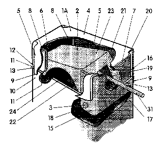
Figure 3 is an isometric view of the mullion Latch of this invention, showing
the housing
engaged with a fragmentary portion of the upper part of a mullion post, having
a cut-out of the top
and side of the housing to show the lever or latch bar. Also shown is a cut-
out of the back of the
mullion post showing the back of the housing with a metal rod passing through
openings in the
backs of both the lever bar and the housing, which rod may be used to
disengage the latch bar.
Figure 3a is an isometric view of the cover, which may be made of metal,
plastic or other
material. The cover is made to plug into the housing of the mullion latch to
cover the opening for
inserting the disengaging tool illustrated as a rod which may be used to
disengage the lever (latch]
bar. 'The cover hides from view and protects the lever bar from dirt and grime
and gives the
appearance of a continuous mullion post.
Figure 3b is an isometric view of the inside of the cover showing the
disengaging device
7
CA 02254705 1998-12-O1
Case PFC I 1998cip
attached to the inside back of the cover.
Figures 4, 5 and 6 are sectional side. back and bottom views, respectively, in
general
alignment with each other, showing the detail of the mullion latch including
the housing and lever
bar mounted on the top of a fragmentary portion of the upper part of a mullion
post.
Figures 7, 8 and 9 are sectional side views of the mullion latch including the
housing and
latch (lever) bar showing the progressive operating stages of the mullion
latch bar in successive
operating modes of removing the mullion from its installed position. The
installation mode is
essentially the reverse of the operation stages shown.
Figures 10, 1 1 and 1 ? are isometric views of three different mullion posts
that are in
commercial use also showing adapters of this invention for retrofitting the
mullion posts to employ
the mullion latch of this invention.
BRIEF DESCRIPTION OF THE INVENTION
The following Brief Description of the Invention is best understood with
reference to
Figure 3, which is an isometric view of the secured mullion latch of this
invention, showing the
housing engaged with a fragmentary portion of the upper part of a hollow
mullion post, having a
cut-out of the top and side of the housing to show the lever (latch) bar. Also
shown is a cut-out of
the back of the mullion post which shows the back of the housing and the
disengaging device,
which is illustrated as a rod, which may be used to release the latch bar. The
rod which passes
through openings in the back of the lever bar. 2I , and the back of the
housing, 7, which openings
create a passage for the rod through the housing and underside of the lever
bar. The rod releases
8
CA 02254705 1998-12-O1
Case PFC I 1998cip
the lever bar from its engaged position when downward pressure is applied on
the exposed portion
of the rod, thereby permittin<V the removal of the mullion post.
The mullion Latch, 1, in accordance with this invention is preferably
rectangular in shape
and comprises a housing, l a, and a lever bar. 2, including a pivot pin, 3.
The housing has a top,
4, two sides, 5, that are equivalent in shape, a front, 6, and a back, 7. The
top, 4, of the housing,
is adapted so that it may be secured in the center of the header of a double
door frame, for example
by screws. 32. as shown in Figures 1 and ?. The front, 6. and back. 7. of the
housing face the
outside and inside of the doors. respectively. 'The two sides, 5, of the
housing have an extension,
9, that goes on the outside of the mullion post, 10, (shown in the engaged
position), and below the
joint, 1 1, made between the bottom- lips, 12, and the top-lip, 13, ofthe
mullion post, 10. In
similar manner the front, fi, of the housing extends so that the front bottom-
lip, 12, also fits onto
the top-lip, l3, of the mullion post, 10, when it is locked. The front, 6, of
the housing is shaped to
have two front-wings, 8, that fit within the sides, 5, of the housing, 1 a.
The front bottom-lips, 12,
of the front-wings, 8, of the housing also fit onto the top side-lips, 13, of
the mullion post. I 0. An
extension, 14, of the back, 7, of the housing extends below the two sides, 5,
and is shaped to go
inside the back top-lip, 13, of the mullion post, 10, when engaged. The back.
7, of the housing
is shaped to have two back-wings, 15, that fit within the mullion post, 10, to
form a channel, I 6,
between the inside surface of the sides, 5, of the housing and the outside
surfaces of the back-
wings, 15. Said channel, I 6, is sized to receive the thickness of the top-
lips, 13, of the hollow
mullion post, 10, when engaged. The back, 7, of the housing is also shaped so
that the back
9
CA 02254705 1998-12-O1
Case PFC I 1998cip
bottom-lips, 17, tit into the back of the mullion post, 10. The extensions of
the back-wings, 15.
which are below the front bottom-lips. I ?. of the front, 6, and sides, ~, are
sufficient to allow for
holes, 18, to receive a pin, 3, which pivots the lever bar, 2, which will be
described later. The
holes, I 8, are below sides, >. and are positioned to be covered by the top of
the mullion post, 10,
when it is engaged, but to be accessible when the housing, I a, is separated
from the mullion post,
I U. The back, 7, has an opening. 19. above the line of the joint, 1 I , of
the housing, 1 a, and the
mullion post, 10, to permit access to the bottom of the lever bar. ?, through
opening, 20, in the
back of the lever bar. 21, when the housing, la, containing the lever bar. 2,
is engaged with a
mullion post, 10 so that it may be moved to the disengage position by use of a
simple article such
as a rod, shaft of a screw driver. handle of a pliers or even a writing
instrument such as a pen or
pencil, thereby allowing for the easy removal of the mullion post.
The lever bar, 2, is shaped to fit snugly within the housing, la. The lever
bar, 2, is secured
in the rear of the housing which faces the inside of the doors, by a pivot
pin. 3, which is inserted
into the two complimentary holes, 18, provided in the back-wings, 15, and the
corresponding
holes (not shown in Figure 3) in the sides, 22, of the lever bar, 2. The back,
2I , of the lever bar, 2,
has an opening, 20, which is accessible through an opening, 19, in the back of
the housing, 7,
which openings create a passage through the housing and the underside of the
lever bar for use of
the disengaging tool. The top, 23, of the lever bar, 2, is flat so that when
depressed, the top, 23,
flat surface of the lever bar, 2, meets flush with the top inside surface of
the housing, 1 a. The two
sides, 22, of the lever bar, 2, have saddle shaped cut-outs, 24 . These saddle
shaped cut-outs, 24,
IO
CA 02254705 1998-12-O1
Case PFC 11998cip
are shaped to allow for the removal of the mullion post, 10, to be raised high
enough so that the
mullion post, 10, will clear the floor base plate, 30, and its retaining
protrusions, 33, (not shown
in Figure 3 ) when being disengaged. The front, 25, of the lever bar, 2, has a
top-lip and two side-
lips (not shown in Figure 3 ) which are contoured so that when in the locked
position a cam action
is created which tightens and locks the engaged mullion post, I 0, in a fixed
position.
DETAILED DESCRIPTION OF THE INVENTION
Referring to Figures 1 through 12:
higure 1 illustrates an elevation view of a double doorway viewed from the
inside having
swinging doors. 28, mounted within a door frame in closed position, having a
door frame header,
26, door frame sides, 27, swing doors, 28, fitted with panic rim hardware, 29,
and showing the
removable mullion, 10, between the doors fitted onto a base plate, 30, and its
retaining protrusions,
33, and locked in place at the top by the mullion latch, l, thereby locking
the mullion post at both
the top and bottom of the door frame.
Figure 2 illustrates an expanded elevation view from inside of the swinging
doors. 28,
showing the mullion latch housing, l , secured in the door frame header, 26,
by screws, 32, or
other attaching means. The openings, 19 and 20, are shown exposed to
illustrate the ease and
accessibility for disengaging and removing the mullion post, 10.
Figure 2a illustrates an expanded elevation view from inside of the swinging
doors, 28,
showing the floor plate, 30, and its retaining protrusions, 33. The floor
plate, 30, is secured to the
door by screws or other attaching means (not shown). The retaining
protrusions, 33, are of a
11
CA 02254705 1998-12-O1
Case PFC 11998cip
sufficient height to engage the mullion post, 10, securely in position when it
is in the installed
vertical position, but not so high as to inhibit the removal of the mullion
post, I 0. In general the
height of the retaining protrusions, 33, should be slightly less than the
depth of the saddle cut-outs,
24, in the lever bar, 2. Since the retaining protrusions, 33, will be exposed
when the mullion post,
l 0, is removed to make way for the passage of equipment. furniture, and the
like through the open
double door frame, it is preferred to maintain the retaining protrusions, 33,
in a low profile height.
Figure 3 is an isometric view of the mullion latch, 1, of this invention,
which has been
described in detail in the BRIEF DESCRIPTION OF THE IN VENTION, it shows the
mullion
latch housing, l , engaged with a fragmentary portion of the upper part of a
mullion post, 10,
having a cutout of the top, 4. and side, 5, of the housing to show opening I
9, in the back of the
lever bar, 21, and a cut out of the back of the mullion post, I 0, to show the
back of the housing, 7,
having opening, ?0, which opening allows for the insertion of a disengaging
device.
Figure 3a is an isometric view of the cover, 34, which may be made of metal,
plastic or
other material. The cover. 34. has a back, 35, and sides. 36, and a lug, 37.
The lug, 37, plugs into
the opening, 19. The back. 35 of the cover, 34, rests on the back lip, 13, of
the mullion post, 10,
and the sides, 36, fit into the channel, 16, and cover the back portion of the
back wings, 15, thereby
covering the back, 7, of the exposed portions of the housing and the back
portion of the sides which
are exposed to give the appearance of a continuous mullion post
Figure 3b is an isometric view of the inside of the cover showing the
disengaging
device attached to the inside back of the cover. In this embodiment of my
invention, the lug, 37,
which retains the cover in place, is not required. The cover is fitted with
the disengaging device by
12
CA 02254705 1998-12-O1
Case PFC l 1998cip
simply attaching a rod or bar. to the inside back of the cover. The cover is
kept in place by the
weight of the disengaging device which passes through the openings, '?0 and
19. and resides
inside the mullion latch, 1. when not in use. The disengaging device should be
of sufficient length
to reach the bottom front of the lever bar, 25, and of sufficient strength to
lift the lever bar, 2, when
leveraged or triggered. The rod. 3 I . should be set at a downward angle so
that its length is parallel
or somewhat lower than parallel, to the angle of the top of the lever bar, 23,
when it is in the
engaged position, thereby allowing for the tree movement of the lever bar, 2.
Figures 4, > and b are sectional side. back and bottom views. respectiveiv. in
<~eneral
alignment with each other, showing the detail of the mullion latch housing, 1
a, and lever bar, 2,
mounted on the top of a fragmentary portion of the upper part of a mullion
post. 1 U.
Figure 4, the sectional side view of the mullion latch of this invention,
illustrates the detail
of the mullion latch , 1, with openings, 19 and 20, to allow for the insertion
of a disengaging tool
for release of the latch bar, 2, when in the engaged position. It should be
noted that the front
surface of the lever bar, 25. tightly engages the inside surtaces of both the
front of the housing, ~,
and the top of the mullion post, 10, thereby providing a secure solid
engagement, or locked
position, so that there is no movement of the installed mullion post, I 0,
even when the swinging
doors are slammed or by equipment bumping the mullion post when passing
through. This locked
position is provided for by the position of the pivot pin, 3, so that it
provides a cam like action at
the front surface, 25, of the lever bar, 2. Furthermore, by positioning the
pivot pin, 3, close to the
back of the housing, 7, the weight of the lever bar, 2, is concentrated in
front of the pivot pin, 3, in
the locked position, to provide the locking action without using a spring
mechanism. Figure 4 also
13
CA 02254705 1998-12-O1
Case PFC I 1998cip
shows the top of the mullion post, 10, and the top lip. 13, of the mullion
post, I 0. and bottom lip
of the housings front and sides. 1?. forming point, 1 l, which is a loose
fitting~oint, between the
bottom lip, 1'Z, of the front of the housing, 1, and the top lip, 13, of the
mullion post, I 0. By this
arrangement the mullion post, 10. is prevented from being raised and is
immobilized in the vertical
position.
Figure 5 which is a back view of Figure 4 which shows the detail of the
mullion latch
housing, la. Figure ~ also illustrates that the back of the housing, 7, with
opening ,?0, and back
wings. 1 ~, also conform in size and shape to the inside of the mullion post,
10. but in a manner that
leaves a space between back wings, 1 >, and housing sides, 5, creating
channel, I 6, for the top of the
mullion post, 10, to slip into.
Figure 6 which is a bottom view of Figure 4 shows the detail of the mullion
latch housing,
1 a, and illustrates the shape of the back wings, 15, and front wings, 8. Also
shown is the shape and
width of the lever bar, ?, within back wings, 15, and also showing opening,
20. This view also
shows the channel, I 6. which is between the housing sides, 5 and back wings,
I 5. Figure 6 also
illustrates that the front of the housing, 6, and front wings, 8, conform to
the size and shape of the
mullion post, 10.
Figures 7, 8 and 9 are sectional side views of the mullion latch including the
housing and
latch bar showing the progressive operating stages of the mullion latch bar
when removing the
mullion from its installed position. The installation mode is essentially the
reverse of the operation
stages shown.
Figure '7 shows the mullion latch, l, and mullion post, 10, in the installed
position. The
I4
CA 02254705 1998-12-O1
Case PFC 1 I998cip
lever bar, ~?, is in the down position, showing the tight fit and locked
position between the front of
the lever bar, 25, and the back surface of the extension of the housing, 14,
and the inside surface of
the mullion post, 10, thereby tirmly securing the mullion post, 10, in the
vertical position. Figure 7
also shows a disengaging device, a rod, 44, in position to release lever bar,
2, from the engaged
position. .
Figure 8 shows the lever bar, ?, in the raised position, showing that the
locked position
between the front of the lever bar. 2~, and the inside surfaces of the front,
b, of the housing and the
inside surface of the mullion post. l 0, has been unlocked. This is
accomplished by simply tripping
rod, 44, to its downward position. This unlocking alIow~s the mullion post,
I0, to be backed out of
the mullion latch, l, while the bottom of the mullion post, 10, is still
partially engaged in the floor
plate, 30. (Figure 1 and Figure 2a, show the bottom of the mullion post, 10,
and the floor plate, 30,
in the engaged position. ) The unlocking of the top of the mullion post, 10,
from the mullion latch,
I , is allowed for by the saddle cut-outs, ?4, which permit the top of the
mullion post, t 0, to be
raised into the saddle cut-out spaces, when the mullion post, l 0, is lifted
to disengage it from the
floor plate, 30, and its retaining protrusions, 33.
Figure 9 shows the lever bar, ?, still in the raised position with the mullion
post, l0, being
lowered so that the top lip, 13, is moved downward out of the mullion latch,
1, thus permitting easy
removal of the mullion post. 10, from the door frame, by one person. (Figure 1
and Figure 2a,
show the bottom of the mullion post, 10, and the t7oor plate, 30, in the
engaged position,
maintained in place by retaining protrusions, 33).
It should be noted that the pivot pin, 3, is positioned below the bottom lip,
I2, of the
CA 02254705 1998-12-O1
Case PFC 11998cip
housing front and at the back of the lever bar, 2. This positioning not only
permits a cam like action
at the front surface, 25, of the lever bar, ?, that locks in the mullion post,
I U, but also allows for the
mullion post. 10, to be easily installed by one person. From Figures 4, 5, and
6, it can be seen that
the weight of the lever bar. ?. is concentrated in front of the pmot pin, 3,
and because of its free
swinging action is readily raised by the top of the mullion post, 10, when the
mullion post. 10, is
lifted into the installed position. When the mullion post, 10, is in the
vertical position, the weight
of the free swinging lever bar, ?, positions itself in the locked position,
and it is not necessary to
touch the latch bar, ~, during mstailation of the mullion post, 10, to the
vertical position. The
channel, 16, which is located between the back wings, 15, and housing sides,
5, allows for the
mullion post, l 0, when in the engaged position, to cover the pivot pin, 3,
and complimentary holes,
I 8, in the extensions of the back wings, thereby hiding them from exposure in
the installed
position. The function of channel, I 6, is to receive the top lips, 13, of the
mullion post, 10, when
being installed, so that the top lips, I 3, of the mullion post, 10, may
engage the bottom lips, 12, of
the housing front, 6, and wings, 8, thereby providing a flush fit and support
between the mullion
post, 10, and the mullion latch, 1, of this invention.
Figures I 0, 1 I and 12 are isometric views of three different mullion posts
that are in
commercial use and showing adapters of this invention for retrofitting the
mullion posts to employ
the mullion latch of this invention.
Figure 10 shows the adapter, 39, in line with one ofthe more common
commercially
installed movable mullion posts, 38. In accordance with this invention the
adapter, 39, includes
an insert, 40, shaped to tit snugly into the hollow core space , 41, ofthe
mullion post, 38. The
I (i
CA 02254705 1998-12-O1
Case PFC I 1998cip
length of the insert, 40, is sufficient to slip into the hollow core space,
41, of the mullion post, 38.
to form a stabilized connection between the surfaces of the parts in contact
with each other. It is
preferred that all the surfaces of the hollow core space, 41. of mullion post,
38, be in contact with
all the outside surfaces of the insert, 40; however, it is only necessary for
enough of those surfaces
to be in close enough contact to provide a snug and stabilized fit. The
adapter, 39, also includes a
top portion, 42, which has a hollow core space, 43, that is shaped and sized
to conform and fit the
rectangular shape of the mullion latch, 1, of this invention, which conforms
to the shape of the
standard rectangular mullion post, I 0. used m describing this inventton. The
top portion. 42, of
the adapter, 39, is of a length so that it may be engaged into the mullion
latch, 1, of this invention,
and it may be made from a cut-ot~'piece of a standard mullion post because it
will be engaged in the
mullion latch, 1, in the same manner as that described in connection with
Figures 7. 8, and 9 for
installing or removing the mullion post, 10. In order to use the adapter, 39,
of this invention with
an existing mullion post, 38, to retrofit the installation in accordance with
this invention, a piece of
the top of the mullion post, 38, is cut off so that the mllion post, 38, will
match the length between
the floor plate, 30, and the front lip, I 2, of the mullion latch, 1.
accordingly, by cutting off a piece
of the top of the mullion post, rather than from the bottom, the fittings for
the panic rim locking
mechanism are in the same height and position from the floor in the
retrofitted mullion post as they
were in the original mullion post, thereby obviating any changes in the
location of such hardware,
and further, the existing floor plate and retaining protrusions may be used as
is. The retrofitted
mullion post employing the adapter of this invention is installed and removed
in the same manner
described herein, as for example in connection with Figures 7, 8, and 9. and
may be readily inserted
I7
CA 02254705 1998-12-O1
Case PFC I 1998cip
and removed from the door frame. as many times as desired, realizing the
advantages and
objectives of this invention. The mullion latch- l, ofthis invention is
capable of being employed
with various shaped movable mullion posts, 38. already installed and in use in
existing structures
through out the world, as is further exemplified in the following Figures.
Figures I I and 12 show the shapes of other movable mullion posts, 38, in
commercial use
that may be retrofit, by the retrofit assembly kit provided in accordance with
this invention All
that is required to retrofit an existing movable mullion post, to employ the
mullion latch of this
invention. is to employ an adapter. 39, having an insert. such as. 4U, which
conforms in shape and
contour to the cross section of the hollow core in the movable mullion post,
38, and which also has
a top portion, 41, conforming m shape to the mullion latch of this invention.
Thus, in accordance
with the foregoing disclosure, the retrotit assembly kit of this invention
comprises a mullion latch
and an adapter; a cover for the lever bar opening and a hollow core mullion
post also may be
included.
It should be understood that Figures 10. 1 1 and I? show an adapter, 39, which
has a top
portion, 42, which is the preferred rectangular shape, which happens to be one
of the more
prevalent shapes for removable mullion posts currently in commercial use.
Further, it should be
understood that this invention is also applicable to converting permanently
installed mullion posts
to become removable mullion posts. For example, in those installations where
the mullion post is
welded to the double door frame header, all that is required to convert it to
a removable mullion
post in accordance with this invention is to cut out the permanently installed
mullion post at the
header and extract the bottom of the mullion post from the floor. The mullion
latch of this
18
CA 02254705 1998-12-O1
Case PFC I 1998cip
invention is installed in the header. and the t7oor plate with its retaining
protrusions are installed
beneath it an the floor, thereby allowing for a removable mullion post to be
engaged in accordance
with this invention. Double door frame assemblies that are hollow core and
made of metals such as
iron, steel. aluminium, or reinforced plastics and the like may be suitably
used with this invention.
Obviously, and with out departing from the intent and scope of my invention.
the mullion latch of
this invention may be made to conform in shape and cross section with any of
the cross sections of
the other shapes of mullion posts in use, such as those shown in Figures I0. I
I, and l2, and which
are given as examples. and still other cross section shapes of mullion posts,
not shown. In such
cases all that is necessary is to employ a shape or cross section of an
adapter insert, 40, to conform
and compliment each other so they fit together.
The means employed for disengaging the lever bar when in the engaged position,
may be of
any type such as the rod, 3I, shown in the Figures. Alternatively, any device
may be employed
such as the shaft of a screw driver, the handle of a pliers, a metal bar, or a
pencil or pen, which is of
sufficient strength and length to disengage the lever bar from its secured
position, when triggered
or levered. The length of the disengaging device employed should allow it to
reach the underside
of the front of the lever bar when passed through the openings in the backs of
the housing and lever
bar and still be long enough to protrude out side the openings to allow for
triggering or levering it
to release the lever bar from the engaged position. The shortest length
employed should allow the
disengaging device to reach beyond the center of the saddle shaped cut-outs,
?4, and extend out of
opening, 19, su~ciently to allow for triggering or levering the exposed end of
the device. The
disengaging device may be attached to the cover, as described earlier with
reference to Figure 3b,
19
CA 02254705 1998-12-O1
Case PFC I 1998cip
thereby providing a unitary system and all the components for one person
uninstalling the
removable mullion post.
The openings, 19 and 20, may be of various sizes and shapes. Shapes of the
openings may
be square, rectangular, circular, oval, among other geometric shapes. All that
is required is that the
shape of the openings be substantially in line with each other to create a
passage through the
housing and underside of the lever bar to allow for the disengaging device to
be able to be inserted
through the passage in a manner which permits the disengagement of the lever
bar from the locked
position when it is desired to remove the mullion post. The two openings are
positioned on the
back of the lever bar and the back of the housing thereby allowing the pass
through of the
disengaging device to the release position on the bottom of the lever bar, as
described earlier.
Although I have exemplified my invention using preferred embodiments thereof,
it is
understood that departures may be made therefrom within the scope of my
invention, which is not
limited to the details disclosed herein, but is to be accorded the full scope
of the appended claims
so as to embrace any and all equivalents.