Sélection de la langue

Search

Sommaire du brevet 2254822 

Énoncé de désistement de responsabilité concernant l'information provenant de tiers

Une partie des informations de ce site Web a été fournie par des sources externes. Le gouvernement du Canada n'assume aucune responsabilité concernant la précision, l'actualité ou la fiabilité des informations fournies par les sources externes. Les utilisateurs qui désirent employer cette information devraient consulter directement la source des informations. Le contenu fourni par les sources externes n'est pas assujetti aux exigences sur les langues officielles, la protection des renseignements personnels et l'accessibilité.

Disponibilité de l'Abrégé et des Revendications

L'apparition de différences dans le texte et l'image des Revendications et de l'Abrégé dépend du moment auquel le document est publié. Les textes des Revendications et de l'Abrégé sont affichés :

  • lorsque la demande peut être examinée par le public;
  • lorsque le brevet est émis (délivrance).
(12) Demande de brevet: (11) CA 2254822
(54) Titre français: AMELIORATIONS RELIEES AUX MOTEURS A COMBUSTION INTERNE A REFROIDISSEMENT PAR LIQUIDE
(54) Titre anglais: IMPROVEMENTS RELATING TO THE LIQUID COOLED I.C. ENGINES
Statut: Réputée abandonnée et au-delà du délai pour le rétablissement - en attente de la réponse à l’avis de communication rejetée
Données bibliographiques
(51) Classification internationale des brevets (CIB):
  • B60K 11/04 (2006.01)
  • F01P 05/10 (2006.01)
  • F01P 05/12 (2006.01)
  • F01P 07/14 (2006.01)
  • F01P 07/16 (2006.01)
  • F04D 13/02 (2006.01)
  • F04D 15/02 (2006.01)
  • F04D 29/42 (2006.01)
  • F04D 29/60 (2006.01)
(72) Inventeurs :
  • SAYERS, JONATHAN ALAN (Royaume-Uni)
(73) Titulaires :
  • CONCENTRIC PUMPS LIMITED
(71) Demandeurs :
  • CONCENTRIC PUMPS LIMITED (Royaume-Uni)
(74) Agent: MCCARTHY TETRAULT LLP
(74) Co-agent:
(45) Délivré:
(22) Date de dépôt: 1998-11-26
(41) Mise à la disponibilité du public: 1999-06-03
Licence disponible: S.O.
Cédé au domaine public: S.O.
(25) Langue des documents déposés: Anglais

Traité de coopération en matière de brevets (PCT): Non

(30) Données de priorité de la demande:
Numéro de la demande Pays / territoire Date
9725621.8 (Royaume-Uni) 1997-12-03

Abrégés

Abrégé anglais


A liquid cooled internal combustion engine cooling system comprising a
radiator 10, and an impeller 18 mounted on a drive shaft 20 and forming part of
the radiator assembly. Preferably a compartment in the radiator header tank is
used as an impeller chamber and the chamber may be closed by a plate carrying
a bearing and a seal for co-operation with the drive shaft from the drive motor
12.

Revendications

Note : Les revendications sont présentées dans la langue officielle dans laquelle elles ont été soumises.


Claims
1. A liquid cooled internal combustion engine cooling system comprising a
radiator assembly having a radiator, and an impeller mounted on a drive shaft
and forming part of the radiator assembly.
2. A system according to Claim 1 wherein the radiator comprises a header tank
which is adapted to form a chamber for the impeller.
3. A system according to Claim 2 wherein the chamber is closed by a plate
carrying a bearing and a seal for co-operation with the drive shaft.
4. A system according to any preceding claim wherein the drive shaft carries a
separate and distinct drive, which is preferably a motor such as an electric
motor.
5. A system according to any preceding claim comprising a controller for
controlling the operation of the drive in response to predetermine engine
temperature characteristics.
6. A system according to Claim 5 wherein the controller comprises part of an
engine management system for a vehicle and/or comprises a thermostat
which monitors the engine temperature of a vehicle.
7. A system according to Claim 5 or 6 wherein the controller enables an engine
to reach a desired operating temperature before actuating the motor thereby
to commence cooling of the engine.
8. A system according to any of Claims 5, 6 or 7 wherein the controller enables
continued operation of the pump after an engine ignition has been turned off,
thereby to ensure continued cooling of an engine.

9. A system according to any preceding claim comprising two or more
impellers, and/or valving arrangement allowing diversion of the coolant so
that it does not necessarily pass through the radiator.
10. A system according to Claim 9 comprising two or more impellers in parallel,
or independent of one another.
11. A system according to Claim 9 or 10 comprising two or more impellers in
series with one another thereby to provide a multiple stage pump.
12. A system according to any preceding claim wherein the impeller and motor
are magnetically coupled through a relatively stationary and relatively
non-magnetic plate.
13. A system according to any preceding claim wherein the drive shaft comprises
a pulley operably having a drive belt for co-operation with drive means such
as an engine crankshaft thereby to drive the impeller.
14. A system according to any preceding claim wherein a separate chamber
housing is provided which is connectable to the radiator so as to form a
complete unit.
15. A system according to any preceding claim wherein a radiator header tank is
provided having one or more pump components such as a chamber, inlet or
outlet for example, formed therein during manufacture.
16. A system according to Claim 15 wherein the header tank is formed by
injection moulding or diecasting to provide the one or more pump
components.

Description

Note : Les descriptions sont présentées dans la langue officielle dans laquelle elles ont été soumises.

CA 022~4822 1998-11-26
KJB/sjp~3290
IMPROVEMENTS RELATING TO THE LIQUID
COOLED I.C. ENGINES
This invention relates to liquid cooled internal combustion or I.C.
engines. It is conventional to provide a coolant circuit including a radiator
allowing heat exchange between the coolant and for example a fan driven flow
of ambient air. The coolant is driven from engine to radiator and vice versa viaflexible hoses which allow for relative movement of the engine and radiator, by
a so-called water pump having an impeller mounted on a drive shaft also
carrying a pulley. The impeller is located in a chamber in the engine, on the face
of the cylinder block adjacent the radiator, and the pulley is engaged by a vee
belt driven from the cr~nk~h~ft and often also serving to drive an alternator and
the fan, in the latter case possibly via an electric clutch allowing the fan to turn
or not according to control applied by an engine management system or in
simpler versions under the control of a thermostat sensing coolant temperature.
The impeller, drive shaft and a plate closing the impeller chamber and
containing bearing and seal form a single unit which is replaceable. The usual
reasons for replacement are leakage caused by chemicals, dirt or impurities in
the coolant, or wear caused either by long use, or quite frequently by improper
use such as over tightening the drive belt which places undue load on the
bearing or seal.
An object of this invention is to provide improvements over the prior art.
..... .. . . .

CA 022~4822 1998 -11- 26
According to the one aspect of the invention there is provided a liquid
cooled I.C. engine cooling system comprises a radiator, and an impeller
mounted on a drive shaft and forming part of the radiator assembly.
Hence, a compartment in the radiator header tank, assuming a vertical
flow radiator in this instance, may be used as an impeller chamber, and the
chamber may be closed by a plate carrying a bearing and a seal for co-operation
with the drive shaft.
Preferably, the drive shaft carries a separate and distinct drive motor,
which will usually be an electric motor. The motor may be under the control of
an engine management system or a thermostat and this gives a completely new
control in engine management. Hitherto, as far as the applicants are aware, it
has only been the coolant fan which has been controlled in this way. The
significance of controlling the water pump by the same or a similar system is
that power utilization in driving the pump is avoided at times when the pump is
unnecessary, that is when the coolant temperature has not risen to a point whereheat exchange is required, and moreover rise in engine temperature to the
required range can be more rapidly controlled. These factors can lead to
substantially improved fuel consumption as compared to what is possible with
known designs. Additionally, the system can continue to cool an engine even
after the ignition has been turned off - for example to ensure a predetermined
non-operating temperature is reached.
Independence of drive from engine speed also allows water pump
operating speed to be selected in terms of efficiency. For example, when an
engine is idling and a vehicle is stationary in traffic, it may be desirable for the
pump to operate at maximum speed (assuming that speed variation is a
possibility with the chosen design) whereas when the vehicle is travelling lower
.... .. ..

CA 022~4822 1998-11-26
pump speeds will be possible. This in general is a reverse of what is provided
by the conventional arrangements.
Again, whilst the foregoing description is solely in relation to engine
cooling, the same possibilities exist where the coolant is used for other purposes
for example as part of the heating system of a vehicle. In such instances it maybe that operation of the impeller or an impeller to drive engine coolant via theheating system is required at times when engine cooling is not required, and theinvention contemplates the use of multiple impellers and/or valving
arrangements allowing diversion of the coolant according to requirements for
the different purposes. Multiple impellers can be used in parallel (effectively
multiple pumps) or in series thereby effectively to provide a multiple stage
pump. Accordingly, for a parallel arrangement or suitable valve arrangement,
coolant flow to the radiator can be restricted or elimin~ted and flow can be
directed to other components of a vehicle or engine.
Another possibility with the use of an electric motor is to make a
magnetic coupling between the impeller and the motor so that the plate carrying
the shaft bearing can be completely closed and again elimin~te risk of leakage to
the exterior. In the event of motor failure, the motor can be replaced without
affecting the integrity of the coolant system.
However, in a development of magnetic coupling, the drive motor may be
replaced by a pulley engaged with a drive belt so that the impeller is belt driven
for example from the engine crankshaft with a magnetic coupling to the impeller
and although this is not as readily susceptible of control, it may be considered to
have advantages as compared to the conventional arrangements and location of
the impeller and water pump. An aspect of the invention encompasses this
.. . .. . .. . .

CA 022~4822 1998 -11- 26
possibility and also that of using a conventional belt drive without even a
magnetic coupling, as long as the radiator location of the impeller is employed.
Instead of providing the impeller chamber in the header tank or like part
of the radiator, it may be located in a chamber housing connected to the radiator
in this case the chamber may also form part of a complete unit which is
replaceable in case of need.
The header tank may have pump components included as part of unitary
injection moulded or die-cast structure and additional components assembled
thereto.
The invention is more particularly described with reference to the
accompanying drawings in which:-
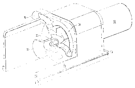
FIGURE 1 is a diagr~mm~tic cut-away view showing an end portion of a
radiator header tank provided with the invention;
FIGURE 2 is a diagr~mm~tic perspective view of a different embodiment;
FIGURE 3 is an exploded view showing the components used in the
Figure 2 construction;
FIGURE 4 is a side elevation of the arrangement shown in Figure l;
FIGURE S is an underneath plan view of the same;
FIGURE 6 is a section taken on the line VI-VI of Figure 4; and
FIGURE 7 is a block diagram of a system according to the invention.
Turning first to Figures 1 and 4 to 7, the embodiment illustrated therein
has the water pump located in one end of the header tank 10 of a vehicle radiator
associated with an I.C. engine. An electric drive motor 12 is mounted on one
end face of the header tank with a suitable interposed seal and bearings provided

CA 022~4822 1998-11-26
either in the header tank itself or in the drive motor construction. Coolant is
drawn in through the inlet 14 located axially and indeed co-axial with the drivemotor, and expelled through the outlet 16 which in this instance is of somewhat
of a "figure of 8" cross-section, thereby providing a pair of passages. This
coolant flow is caused by impeller 18 mounted on drive shaft 20 and housed in
an appropriate volute 22.
Figure 7 shows a schematic block diagram of a cooling system according
to the invention where it can be seen that motor 12 communicates with a
controller 32 such as an engine management system, which controller further
comprises a thermo couple 34 for monitoring ~he engine temperature. Of
course, multiple thermo couples can be used for monitor temperature at
different locations. Accordingly, controller 32 is used to actuate drive motor 12
thereby to effect pumping by impeller 18 as appropriate and/or as predetermined
dependent on the engine speed and/or temperature.
Turning next to Figures 2 and 3 wherein like reference numerals are used
as to those used in Figures 1 and 4-6, for like parts, the motor shaft 20 here
extends normal to the length of the header tank 12. The motor 12 is associated
with a cover 24 which provides a seal to the shaft 20, and the cover closes pumphousing 26 which forms an equivalent to the volute in the Figure 1 construction.The impeller chamber is formed in the pump housing and the impeller 18 lies in
that chamber which is closed by the cover 24.
The pump housing includes flange 28 which is bolted face to face against
a like flange 30 on the header tank.
It will be appreciated that any seal required by an electric motor is much
simpler than one required where a shaft is required to project to a drive pulley:

CA 022F74822 1998-11-26
essentially with the electric motor there will be no rotating part projecting to the
exterior and the motor can be completely "canned".
Whilst the specific embodiments described use centrifugal flow impellers,
this is not essential and axial flow or mixed flow arrangements are possible andmay be advantageous where space considerations are critical.
Further, whilst the invention has been specifically described in relation to
location of the impeller in the radiator header tank, different locations can beprovided around the radiator to suit particular requirements particularly in terms
of space considerations.

Dessin représentatif
Une figure unique qui représente un dessin illustrant l'invention.
États administratifs

2024-08-01 : Dans le cadre de la transition vers les Brevets de nouvelle génération (BNG), la base de données sur les brevets canadiens (BDBC) contient désormais un Historique d'événement plus détaillé, qui reproduit le Journal des événements de notre nouvelle solution interne.

Veuillez noter que les événements débutant par « Inactive : » se réfèrent à des événements qui ne sont plus utilisés dans notre nouvelle solution interne.

Pour une meilleure compréhension de l'état de la demande ou brevet qui figure sur cette page, la rubrique Mise en garde , et les descriptions de Brevet , Historique d'événement , Taxes périodiques et Historique des paiements devraient être consultées.

Historique d'événement

Description Date
Inactive : Page couverture publiée 2008-07-15
Inactive : CIB de MCD 2006-03-12
Le délai pour l'annulation est expiré 2002-11-26
Demande non rétablie avant l'échéance 2002-11-26
Réputée abandonnée - omission de répondre à un avis sur les taxes pour le maintien en état 2001-11-26
Inactive : Page couverture publiée 1999-06-11
Demande publiée (accessible au public) 1999-06-03
Inactive : CIB attribuée 1999-02-03
Symbole de classement modifié 1999-02-03
Inactive : CIB attribuée 1999-02-03
Inactive : CIB en 1re position 1999-02-03
Inactive : Transfert individuel 1999-02-01
Inactive : Lettre de courtoisie - Preuve 1999-01-12
Inactive : Certificat de dépôt - Sans RE (Anglais) 1999-01-11
Demande reçue - nationale ordinaire 1999-01-08

Historique d'abandonnement

Date d'abandonnement Raison Date de rétablissement
2001-11-26

Taxes périodiques

Le dernier paiement a été reçu le 2000-11-06

Avis : Si le paiement en totalité n'a pas été reçu au plus tard à la date indiquée, une taxe supplémentaire peut être imposée, soit une des taxes suivantes :

  • taxe de rétablissement ;
  • taxe pour paiement en souffrance ; ou
  • taxe additionnelle pour le renversement d'une péremption réputée.

Les taxes sur les brevets sont ajustées au 1er janvier de chaque année. Les montants ci-dessus sont les montants actuels s'ils sont reçus au plus tard le 31 décembre de l'année en cours.
Veuillez vous référer à la page web des taxes sur les brevets de l'OPIC pour voir tous les montants actuels des taxes.

Historique des taxes

Type de taxes Anniversaire Échéance Date payée
Taxe pour le dépôt - générale 1998-11-26
Enregistrement d'un document 1998-11-26
TM (demande, 2e anniv.) - générale 02 2000-11-27 2000-11-06
Titulaires au dossier

Les titulaires actuels et antérieures au dossier sont affichés en ordre alphabétique.

Titulaires actuels au dossier
CONCENTRIC PUMPS LIMITED
Titulaires antérieures au dossier
JONATHAN ALAN SAYERS
Les propriétaires antérieurs qui ne figurent pas dans la liste des « Propriétaires au dossier » apparaîtront dans d'autres documents au dossier.
Documents

Pour visionner les fichiers sélectionnés, entrer le code reCAPTCHA :


Pour visualiser une image, cliquer sur un lien dans la colonne description du document. Pour télécharger l'image (les images), cliquer l'une ou plusieurs cases à cocher dans la première colonne et ensuite cliquer sur le bouton "Télécharger sélection en format PDF (archive Zip)" ou le bouton "Télécharger sélection (en un fichier PDF fusionné)".

Liste des documents de brevet publiés et non publiés sur la BDBC .

Si vous avez des difficultés à accéder au contenu, veuillez communiquer avec le Centre de services à la clientèle au 1-866-997-1936, ou envoyer un courriel au Centre de service à la clientèle de l'OPIC.


Description du
Document 
Date
(aaaa-mm-jj) 
Nombre de pages   Taille de l'image (Ko) 
Dessin représentatif 1999-06-10 1 12
Description 1998-11-25 6 244
Abrégé 1998-11-25 1 13
Revendications 1998-11-25 2 75
Dessins 1998-11-25 5 116
Dessin représentatif 2007-01-29 1 16
Courtoisie - Certificat d'enregistrement (document(s) connexe(s)) 1999-02-16 1 115
Certificat de dépôt (anglais) 1999-01-10 1 163
Rappel de taxe de maintien due 2000-07-26 1 109
Courtoisie - Lettre d'abandon (taxe de maintien en état) 2001-12-23 1 183
Correspondance 1999-01-11 1 32