Note : Les descriptions sont présentées dans la langue officielle dans laquelle elles ont été soumises.
CA 02255249 1998-12-15
pescri tp ion
SAFETY APPARATUS FOR HORIZONTAL LIFELINE
Technical Field
The present invention is directed toward a safety apparatus and
more particularly toward a safety apparatus which forms part of a horizontal
lifeline system.
Backgt'ound Art
Horizontal lifelines have been employed for many years to provide
fall protection for workers on elevated structures. In fact, such horizontal
lifelines
are required and have been mandated by safety rules and regulations in many
jurisdictions. Such lifelines normally consist of a rope or cable suspended
between two structures such as the vertical beams of a building or the like
which
may be 10, 20 or even 100 feet apart. A safety harness or safety belt is worn
by
a worker and a lanyard connected to the harness or belt attaches to the
horizontal lifeline or cable. The end of the lanyard may include either a loop
which can freely move along the length of the lifeline or it may include a
pulley or
the like that rolls along the line. This allows the worker to move freely
along the
length of the lifeline to accomplish his intended tasks. In the event that the
worker losses his footing or otherwise falls, the horizontal lifeline, through
the
lanyard and harness or safety belt will arrest the fall and prevent the worker
from
suffering injury. The use of such a lifeline is described, for example, in
U.S.
Patent Nos. 5,332,071; 5,458,214 and 5,598,900.
In order to function properly, the horizontal lifeline must be
sufficiently taught so that the worker's lanyard can easily move across the
same
and so that the lifeline can function as a steadying rail for the worker, if
necessary. However, when the lifeline is sufficiently taught that the same
CA 02255249 2007-01-03
2
assumes a linear or substantial linear configuration, the resistance force
magnitude required to effectively withstand the load impact of a falling
worker
becomes theoretically exceedingly large. In the event of a fall, the
construction
worker ordinarily generates many times his weight in the impact force exerted
by
the lanyard against the cable or lifeline. Thus, the tension in the lifeline
is critical
since this determines the amount of sag in a lifeline which, in turn,
determines
the load amplification by which a vertical fall arrest force applied to the
lifeline is
multiplied by. Therefore, it is important to know the amount of tension
applied to
a lifeline. In fact, the amount of tension is frequently dictated by safety
rules or
regulations in many jurisdictions.
A winch or similar type device is frequently used to tension a
horizontal lifeline when the same is in use. The lifeline is normally
connected to
one anchoring point and then passes through the winch. The winch, in turn, is
connected through an anchoring line to the second anchor point. A winch-like
device for tightening a horizontal lifeline is available through Fujii Denko
of
Japan and is described in their product brochure No. 221.
Because the amount of tension on the horizontal lifeline is critical
and is mandated by regulation, it is important to know what that tension is
and to
adjust the tensioning device accordingly. This normally requires a separate
tension indicator. Such devices may be placed in line with either the
horizontal
lifeline or the anchoring line and may be In the form of a tension gauge or
the
like.
It is also well known that shock absorbers in combination with
horizontal lifelines are desirable to absorb the initial force placed on the
anchoring devices of the lifeline. This enables controlled elongation of the
lifeline
under load to increase the sag angle and, therefore, reduce the amplification
forces on the anchors. At the same time, this prevents shock to the fallen
worker
by allowing him to come to a more gradual stop in the event of a fall. Known
CA 02255249 2007-01-03
3
Types of shock absorbing devices are described, for example, in the
three prior art patents referred to above.
Heretofore, no device has been available which accomplishes all of
the functions described above. Although the shock absorber shown in U.S.
Patent
No. 5,458,214 includes a tension indicating means therein for indicating the
amount of tension on the lifeline, the device is somewhat complex and still
lacks
the additional features described above. There has, therefore, been a need for
a
safety apparatus for use with horizontal lifelines which combines the features
of a
tensioner, adjustable shock absorber and a gauge or indicator.
Disclosure of the Invention
According to the present invention there is provided a safety
apparatus for use with a lifeline which lifeline is comprised of an elongated
rope
intended to be suspended between two fixed supports and placed under a
predetermined amount of tension comprising: a housing; an axle; a pulley wheel
within said housing and fixedly secured to said axle so as to rotate
therewith, said
rope being adapted to extend into said housing and around said pulley wheel so
that rotation of said pulley wheel in a first direction will cause said rope
to come
under tension; handle means mechanically attached to said pulley wheel for
manually rotating said pulley wheel to tension said rope when said handle
means
is moved so as to rotate said pulley wheel in said first direction, and
friction brake
means mounted on said axle and automatically allowing said handle means to
move without rotating said pulley wheel when the tension in said rope reaches
a
predetermined level.
The present invention is designed to overcome the deficiencies of
the prior art described above and provides a safety device or apparatus which
is
capable of tensioning a horizontal lifeline while providing an adjustable
shock
absorber and a gauge or indicator for indicating the amount of tension on the
lifeline. The invention includes a housing which is adapted to be secured to
an
anchor point through an anchoring line. The free end of a horizontal lifeline
passes
over a pulley within the housing and around a number of rollers which are
adapted
CA 02255249 2007-01-03
3a
to maintain the lifeline in secure contact with the pulley. A lever is
utilized to rotate
the pulley in order to tension the lifeline. The lever, however, is
interconnected to
the pulley through an adjustable disk brake which can be preset to a desired
force. When the tension on the lifeline reaches its desired level, the brake
slips
and the lever can freely rotate.
A second series of disk brakes connected to the pulley function as a
shock absorber. In the event of a fall, the initial force on the horizontal
lifeline
exceeds the braking force of the shock absorber brakes and the pulley can
rotate
through a limited number of turns. Eventually, however, the shock absorber
brake
slows the fall and eventually stops the same. The amount of tension on the
shock
absorber brake can also be adjusted to thereby control the
CA 02255249 1998-12-15
4
amount of shock being absorbed. An additional brake mechanism prevents the
lifeline from freely being drawn from the housing in the event of a complete
failure of the mechanism thereof.
Brief Description of the Drawings
For the purposes of illustrating the invention, there is shown in the
accompanying drawings one form which is presently preferred; it being
understood that the invention is not intended to be limited to the precise
arrangements and instrumentalities shown.
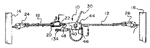
Figure 1 is a schematic representation of a horizontal lifeline
utilizing the safety apparatus of the present invention;
Figure 2 is a schematic representation of the operation of a
conventional horizontal lifeline;
Figure 3 is a cross sectional view taken through the line 3-3 of
Figure 1;
Figure 4 is a cross sectional view taken through the line 4-4 of
Figure 3;
Figure 5 is a cross sectional view of the pulley utilized with the
present invention;
Figure 6 is a cross sectional view taken through the line 6-6 of
Figure 5;
Figure 7 is a view similar to the view of Figure 6 further illustrating
the pulley utilized with the present invention;
Figure 8 is a cross sectional view illustrating an additional braking
mechanism of the present invention, and
Figure 9 is a view similar to Figure 8 showing the additional
braking mechanism in its operative braking condition.
CA 02255249 1998-12-15
Best Mode for Carrying Out the Invention
Referring now to the drawings in detail wherein like reference
5 numerals have been used throughout the various figures to designate like
elements, there is shown in Figure 1 a safety device or apparatus constructed
in
accordance with the principles of the present invention and designated
generally
as 10. The safety device 10 is shown in use with a lifeline 12 comprised of an
elongated rope which is suspended in a horizontal direction between two
vertical
supports 14 and 16. The vertical supports may be the vertical beams of a
building under construction, supports for a bridge or elevated roadway or in
substantially any location where a horizontal lifeline would be required.
The safety device 10 of the present invention is connected to the
vertical support 14 through the use of an anchor line 18. One end of the
anchor
line is connected to a carabiner 20 which, in turn, is secured to an eye hook
22
connected to the safety assembly 10. The other end of the anchoring line 18 is
connected to the vertical support 14 through the use of a spring biased hook
24
and an eyelet 26 connected to the vertical support 14. Similarly, the remote
end
of the horizontal lifeline 12 is connected to the vertical support 16 through
the
use of a spring biased hook 26 and an eyelet 28 connected to the vertical
support 16. As should be readily apparent to those skilled in the art, the
foregoing is by way of example only and numerous other types of connectors
and interconnections can be used to support the horizontal lifeline 12 and the
safety device 10.
The free end of the lifeline 12, that is, the end remote from the
vertical support 16 passes through the safety device 10 in a manner to be
described more fully hereinafter. As will also be described in more detail
below,
a lever 30 is provided on the safety device 10 for tensioning the lifeline 12.
The use of a lifeline 12 is, per se, well known in the art and is
schematically illustrated in Figure 2. A worker 32 wearing a harness 34 is
connected to the lifeline 12 through the use of a lanyard 36. The free end 38
of
CA 02255249 1998-12-15
6
the lanyard 36 may include a loop or pulley or the like that can freely travel
along
the length of the lifeline 12. This allows the worker to move along the length
of
the lifeline to perform whatever duties are required of him. Furthermore,
depending on the length of the lanyard 36, the worker can also move to either
side of the lifeline. In the event of a fall, however, the lifeline 12,
through the
lanyard 36 and harness 34, prevents the worker 32 from serious injury by
arresting the descent. Figure 2 also illustrates the force vectors on the
lifeline 12
resulting from a fall of a worker 32 which are, per se, well known in the art.
The safety device 10 of the present invention is comprised
essentially of a housing having a front wall 40 and a rear wall 42
interconnected
but spaced apart from each other through the use of appropriate nuts and bolts
such as shown at 44, 46 and 48 at the periphery thereof. Extending through the
interior of the housing formed by the walls 40 and 42 is an axle 50 having a
center portion 52, a forwardly extending portion 54, and a rearwardly
extending
portion 56. The axle 50 is mounted for rotation within the housing through the
use of appropriate bearings 58 and 60 secured to openings formed in the front
and rear walls 40 and 42, respectively.
A pulley wheel 62 is fixed to the central portion 52 of the axle 50
within the space between the front and rear walls 40 and 42. The pulley wheel
62 is secured to the axle 50 so as to positively rotate therewith.
As shown most clearly in Figures 5-9, the inner side walls of the
pulley 62 are formed with a plurality of ribs such as shown at 64 and 66. The
size and shape of these ribs 64 and 66 along with the dimensions of the pulley
wheel 62 and the horizontal lifeline 12 provide a substantially positive
gripping
force on the lifeline 12. This essentially prevents any slippage between the
lifeline 12 and the pulley wheel 62 when the lifeline passes around the pulley
wheel. The importance of this will become more readily apparent hereinafter.
Referring now to Figure 3, the forwardly extending end 54 of the
axle 50 is fitted with a pair of circular disks 68 and 70. The disks 68 and 70
are
keyed to the shaft end 54 so as to positively rotate therewith. Located
between
CA 02255249 1998-12-15
7
the disks 68 and 70 is an additional disk 72 which is free to rotate about the
end
54 of the axle 50. The outer edge of disk 72 is welded or otherwise secured to
a
cylindrical member 74 which is likewise free to rotate about the axle 50 in
unity
with the disk 72. The lever 30, also shown in Figure 1, is secured to the
outer
surface of the cylinder 74 and extends outwardly so as to be easily grasped by
a
worker so that the same can be rotated about the axis of the axle 50 along
with
the cylindrical member 74 and the disk 72.
Located between the disk 68 and the disk 72 is a friction brake pad
76. A similar friction brake pad 78 is located between the disk 70 and the
disk
72. A nut 80 is threaded onto the end of the shaft end 54 of the axle 50 and
can
be used to tighten a spring washer 82 against the disk 70 to compress the
series
of disks 68, 70 and 72 against the friction brakes pads 76 and 78.
As a result of the sandwich arrangement of the various disks and
brake pads, it can be seen that with the nut 80 tightened on to the shaft end
54,
the spring washer 82 compresses the various disks and brake pads together.
Accordingly, when lever 30 is rotated, a turning force is applied through
cylinder
74 and disk 72 to the disks 68 and 70 through the brake pads 76 and 78. Thus,
with no resistance force or with some predetermined resistance force on the
pulley 62, rotation of the lever 30 will result in rotation of the pulley 62.
However,
at some predetermined torquing force placed on the lever 30, the force applied
by the brake pads 76 and 78 on the disk 72 will be exceeded and the disk 72
will
merely slip and rotate freely relative to the disks 68 and 70. This
predetermined
force will, of course, be equal to the desired tension on the horizontal
lifeline 12
which will be preventing further rotation of the pulley 62.
The amount of the force applied to lever 30 before the disk 72
begins to slip can be adjusted by tightening or loosening the nut 80. This
adjusts
the amount of spring tension on the sandwich comprised of the disks 68, 70 and
72 and the brake pads 76 and 78 as a result of the spring washer 82. It is,
therefore, possible to include a dial with indicia therein on the outer face
of the
nut 80 relative to the end face of the shaft end 54 whereby the angular
position
CA 02255249 1998-12-15
8
between the nut 80 and the shaft end 54 can indicate a certain predetermined
tension force or a series of different forces with different markings.
The other side of the safety device 10, that is the right side as
viewed in Figure 3, has a similar braking system. Disks 84 and 86 are secured
to
the shaft end 56 of the axle 50 so as to positively rotate therewith. Located
between the disks 84 and 86 is an additional disk 88 which is not locked onto
the shaft end 56 and is free to rotate thereabout. The outer edge of the disk
88
includes gear teeth 90 around the entire peripheral edge thereof so as to be
in
the form of a ratchet as shown more clearly in Figure 4. Although Figure 4
shows only three ratchet teeth, the teeth actually are arranged around the
entire
peripheral edge of the disk 88.
Located between the disks 84 and 88 is a friction brake pad 92. A
similar friction brake pad 94 is located between the disks 86 and 88. A nut 96
is
threaded onto the end of the shaft end 56 and is used to compress a spring
washer 98 against the disk 86 so as to compress the sandwich formed by the
disks 84, 86 and 88 and the friction brake pads 92 and 94. As a result, the
disk
88 which would otherwise be free to rotate relative to the axle 50 will rotate
with
the axle 50 since it is engaged by the brake pads 92 and 94.
Surrounding the disks 84, 86 and 88 and the brake pads 92 and 94
is a cylindrical housing 100 that is fixedly secured to the outer surface of
the side
wall 42. An opening 102 is formed in the wall of the cylindrical housing 100
so as
to make the gear teeth 90 of the disk 88 accessible of the outside thereof as
shown in Figures 3 and 4. A pawl 104 is pivotally mounted to the outside
surface
of the wall 42 so as to pivot about its own pivot point 106. A spring 108
biases
the pawl 104 inwardly through the opening 102 so as to engage the teeth 90 of
the disk 88. A short manually operated lever 110 can be used to pivot the pawl
104 outwardly away from the gear teeth 90 against the force of the spring 108
when it is desired to disengage the pawl 104 from the teeth 90.
Figures 8 and 9 illustrate how the lifeline 12 is arranged within the safety
device 10 of the present invention. Figure 8 shows a device when the lifeline
12
CA 02255249 1998-12-15
9
is in its normal operating condition. It can be seen that the lifeline 12
enters the
end of the safety device 10 from the right as viewed in Figure 8 and passes
under the roller 112 which surrounds the bolt 44. The lifeline12 then passes
around the pulley 62 and out through the right side of the safety device 10
and
downwardly around the roller 114 which surrounds the bolt 46. The free end 116
of the lifeline 12 then passes through a brake mechanism 118. Preferably,
however, a small Ioop120 remains between the roller 114 and the brake
mechanism 118.
The brake mechanism 118 is similar to that shown and described
in U.S. Patent No. 5,156,240. It includes a U-shaped housing 122 having two
side walls and a bottom wall 124. A brake 126 is pivoted to the side walls of
the
U-shaped housing 122 through pivot 128 and includes a series of teeth 130
formed at the lower portion thereof. A spring 132 biases the teeth 130
downwardly so as to slightly compress the lifeline 12. The upper end of the
brake lever 126 is pivoted to the main housing of the safety device 10 through
the bolt 48. As shown most clearly in Figure 9, should the lifeline 12 be
pulled to
the right beyond the braking force of the pulley 62 as will be explained in
more
detail below, the brake mechanism 118 will pivot counterclockwise or to the
right
as viewed in Figure 9. The U-shaped housing 122 will then begin to pivot
clockwise relative to the brake 126 forcing the teeth 138 into the lifeline 12
to
force the same against the bottom wall 124 and thereby prevent any further
withdrawal of the lifeline 12 from the safety device 10. That is, no further
movement to the right will be allowed because of the braking mechanism 118.
As final safety check, a knot 134 is tied in the end of the lifeline 12 so
that, if all
else fails, the lifeline 112 cannot fully disengage from the safety device 10.
The safety device 10 described above is utilized in the following
manner. After the nuts 80 and 96 are tightened to their respective desired
tensioning positions, the safety device 10 along with the horizontal lifeline
12
and the anchoring line 18 are arranged and assembled in essentially the
position shown in Figure 1. The lifeline 12 passes into the housing of the
safety
CA 02255249 1998-12-15
device 10, around the pulley 62 and through the brake mechanism 118
essentially in the manner shown in Figure 8. Once in that position, the
lifeline
112 can be pulled by hand to begin to tension the same since the pulley 62 is
5 free to rotate counterclockwise as viewed in Figures 1 and 8 (clockwise as
viewed in Figure 4). The pulley 62 cannot, however, rotate in the reverse
direction since the pawl 104 engages the teeth 90 of the disk 88.
Once the horizontal lifeline 12 is manually tightened by pulling the
same through the safety device 10, it is properly tensioned by rotating the
lever
10 30 counterclockwise as shown in Figure 1. This can be done by either
rotating
the lever through 360 or by making small rotations and backing up in a ratchet
like manner. Again, as the lifeline 12 is tensioned, it will remain under
tension
and will not loosen even though the force is removed from the lever 30 in view
of
the pawl 104 that engages the teeth 90 in the disk 88. Obviously, however,
when the pulley 62 is being rotated by the lever 30 tensioning the lifeline
12, the
pawl 104 is cammed out of the teeth 90 and engages the next tooth after the
disk 88 stops rotating.
When the proper tension in the lifeline 12 is obtained as
predetermined by the setting of the nut 80, the force applied to the lever 30
will
exceed the braking force created by the brake pads 76 and 78. As a result, the
disk 72 will rotate freely and will not further rotate the pulley 62. As
pointed out
above, a dial can be arranged at the end surface of the nut 80 with an
indication
thereon as to where the nut 80 must be rotated relative to the end of the
shaft
54 so as to achieve any particular desired tension on the horizontal lifeline
12.
After the lifeline 12 is properly tensioned, the end 116 of the lifeline
12 is pulled through the brake mechanism 118 until the loop 120 remains as
shown in Figure 8. It should be readily apparent that the end 116 of the
lifeline
12 can be easily pulled through the brake mechanism 118 from right to left as
viewed in Figure 8 since the brake only works in the reverse direction. The
horizontal lifeline 12 can now be used in its normal manner.
CA 02255249 1998-12-15
11
In the event of a fall by a worker and a sudden increase in force on
the lifeline 12, the pulley 62 will attempt to rotate clockwise as viewed in
Figure
8. This rotation will be resisted by the fact that the pawl 104 engages the
teeth
90 in the disk 88. However, if the force caused by the falling worker on the
lifeline 12 exceeds the braking force created by the brake pads 92 and 94, the
pulley 62 will rotate even though disk 88 is fixed by the pawl 104. The amount
and speed of rotate of the pulley 62, however, will be restricted because of
the
braking force of the brake pad 92 and 94. Thus, although the pulley 62 may
rotate through a number of turns, it will do so relatively slowly thereby
functioning as shock absorber. The amount and speed of this rotation can be
preadjusted by tightening or loosening the nut 96.
After the shock absorber function of the safety device 10 does its
job and the pulley 62 has rotated through a number of turns, the movement of
the lifeline 12 will eventually stop as the loop 120 shown in Figure 8 is
taken up
and drawn around the pulley 62 as shown in Figure 9. At this point, the brake
mechanism 118 will prevent further movement of the lifeline 12. Again, in the
event that all else fails, the knot 134 at the end 116 of the lifeline 12 will
prevent
any further movement of the lifeline 12.
The present invention may be embodied in other specific forms
without departing from the spirit or essential attributes thereof and
accordingly
reference should be made to the appended claims rather than to the foregoing
specification as indicating the scope of the invention.