Sélection de la langue

Search

Sommaire du brevet 2255860 

Énoncé de désistement de responsabilité concernant l'information provenant de tiers

Une partie des informations de ce site Web a été fournie par des sources externes. Le gouvernement du Canada n'assume aucune responsabilité concernant la précision, l'actualité ou la fiabilité des informations fournies par les sources externes. Les utilisateurs qui désirent employer cette information devraient consulter directement la source des informations. Le contenu fourni par les sources externes n'est pas assujetti aux exigences sur les langues officielles, la protection des renseignements personnels et l'accessibilité.

Disponibilité de l'Abrégé et des Revendications

L'apparition de différences dans le texte et l'image des Revendications et de l'Abrégé dépend du moment auquel le document est publié. Les textes des Revendications et de l'Abrégé sont affichés :

  • lorsque la demande peut être examinée par le public;
  • lorsque le brevet est émis (délivrance).
(12) Demande de brevet: (11) CA 2255860
(54) Titre français: EQUIPEMENT TUBULAIRE EN MATERIAUX COMPOSITES REALISES PAR ENROULEMENT DE TISSUS DESEQUILIBRES EN TRAME SUR UN MANDRIN COMPRESSIBLE
(54) Titre anglais: COMPOSITE MATERIAL TUBULAR EQUIPMENT PRODUCED BY WINDING OF WEFT-UNBALANCED WOVEN FABRIC ON A COMPRESSIBLE MANDREL
Statut: Réputée abandonnée et au-delà du délai pour le rétablissement - en attente de la réponse à l’avis de communication rejetée
Données bibliographiques
(51) Classification internationale des brevets (CIB):
  • B29C 53/60 (2006.01)
  • B29C 53/58 (2006.01)
  • B29C 53/82 (2006.01)
  • B29C 63/00 (2006.01)
  • B29C 70/22 (2006.01)
  • B29C 70/30 (2006.01)
(72) Inventeurs :
  • CASTAGNER, BERNARD (France)
(73) Titulaires :
  • BERNARD CASTAGNER
(71) Demandeurs :
  • BERNARD CASTAGNER (France)
(74) Agent: MARKS & CLERK
(74) Co-agent:
(45) Délivré:
(86) Date de dépôt PCT: 1997-05-23
(87) Mise à la disponibilité du public: 1997-11-27
Licence disponible: S.O.
Cédé au domaine public: S.O.
(25) Langue des documents déposés: Anglais

Traité de coopération en matière de brevets (PCT): Oui
(86) Numéro de la demande PCT: PCT/FR1997/000909
(87) Numéro de publication internationale PCT: FR1997000909
(85) Entrée nationale: 1998-11-23

(30) Données de priorité de la demande:
Numéro de la demande Pays / territoire Date
96/06537 (France) 1996-05-23

Abrégés

Abrégé français

Tubes, pieux, mâts en matériaux composites soumis à des efforts de compression axiale ou de flexion, réalisés par enroulement adapté de tissus déséquilibrés en trame, telle que la partie principale de fibres de renforcement, sont placés parallèlement à l'axe longitudinal de la structure. Les tubes, pieux et mâts sont réalisés par enroulement sur un mandrin compressible, pour assurer le démandrinage sans contraindre, ni microfissurer les tubes.


Abrégé anglais


The invention discloses composite material tubes, piles, masts subjected to
axial compression or bending stresses, produced by an adapted winding of weft-
unbalanced woven fabric, such that the main portion of reinforcement fibres is
placed parallel to the longitudinal axis of the structure. The tubes, piles
and masts are produced by winding on a compressible mandrel to ensure that the
tubes are not stressed or subjected to micro-cracking when the mandrel plug is
pulled out.

Revendications

Note : Les revendications sont présentées dans la langue officielle dans laquelle elles ont été soumises.


What is claimed is:
1. A tube in a composite material characterised in that
it is obtained by helically winding fabric in which the fill
or woof is unbalanced with respect to the warp
2. The tube according to claim 1, characterised in that
it is provided by inclining the fabric by an angle equal to
the angle of helical winding.
3. The tube according to one or several of claims 1 and
2, characterised in that the helical winding of the tube is
performed with partial overlapping of successive turns.
4. The tube according to one or several of claims 1 and
2, characterised in that individual widths are butt-jointed
or alternate and successive layers thereof are offset in
order to counterbalance discontinuities due to the individual
widths.
5. The tube according to any one of the preceding
claims, characterised in that the fabric employed is composed
of fibers of a single type or of hybrid fibers.
6. The tube according to any one of the preceding
claims, characterised in that its profile is cylindrical or
oblong.
7. The tube according to any one of the preceding
claims, characterised in that it has a single-walled
structure.
8. The tube according to any one of the preceding
claims, characterised in that it has a sandwich structure

that includes a material having high compression strength
between two tubes.
9. The tube according to any one of the above claims,
characterised in that its winding mandrel is covered with a
layer of compressible material.
10. The tube according to claim 9, characterised in that
the compressible material is a closed cell polyethylene foam.

Description

Note : Les descriptions sont présentées dans la langue officielle dans laquelle elles ont été soumises.

CA 022~860 1998-11-23
TUBULARELEMENTSINCOMPOSITEMATERIALSOBTAINEDBYWINDING
ANUNBALANCED-WEAVEFABRICONACOMPRESSIBLEMANDREL
Numerous structural elements, in particular piles, posts
or masts, are made from steel and, as a consequence, suffer
from disadvantages such as:
a) their significant weight and, in certain cases, the
resultant problems in placing them;
b) their tendency to corrode due to the effects of air,
water or the soil.
c) the cost of their maintenance.
In an attempt to overcome these disadvantages, such
structural elements have been made from aluminium or
composite materials. Regarding such structural elements in
composite materials, the technique that is generally employed
consists in winding filaments of rovings.
Structural elements such as piles, posts or masts should
not only have good breaking strength characteristics but also
be highly rigid when subject to movements which tend to bend
them. To achieve this, it is necessarily for the composite
structure to take full advantage, firstly, of the tensile
breaking and compressional strength of the fibers and,
secondly, of the flexural modulus of the reinforcing fibers.
Thus, the major portion of the latter should be placed along
the axis of the pile, post or mast.
According to the invention, elongated structures such as
piles, posts, masts, beams, are produced by winding,
preferably helically, thermosetting-resin-impregnated glass
fabric impregnated with a a heat-setting resin such as an
epoxy, polyester, or vinyl ester resin.
According to the invention, these fabrics have an
unbalanced weave, in other words have a higher percentage of
filaments in the fill or woof than in the warp. Additionally,
their weave makes angular deformability possible thereby
~ \14h()()\14(.06US DOC -13 nov~mbr~ 1998 -1/7

CA 022~860 1998-11-23
making it possible, according to the invention, to place the
fill or woof filaments parallel to the X- X~ axis of the
structure.
The originality of the design of these high bending-
strength composite tubes of the invention will become clearfrom the description and corresponding technical
justification.
According to the invention, a tube is produced by
helically winding a glass fabric in which the ratio warp/woof
is unbalanced, with c>t, where c is the percentage of the
fiber placed in the warp and t is the percentage of fiber
placed in the woof. The preferred values are between 10 and
25~ for c and between 90 and 75~ for t; this figure for
modularity makes it possible, as a function of
diameter/thickness ratio, to ensure good resistance against
radial buckling.
According to the invention, the tube is built up from
successive layers provided by forward and return helical
winding. On the forward runs, helical winding is done at an
angle of B1 = (90 ~ - a) with respect to the longitudinal
axis and on the return run with an angle of B2 = (90~ + a) .
According to the invention, helical winding is preferably
carried out while giving the fabric an oblique slope of angle
a (see FIG 1) so that the fill or woof 1 is parallel to the
longitudinal axis of the tube, the warp 2 having an angle a
with respect to the circumferential plane 3; this arrangement
improves flexural modulus.
According to the invention, each layer is wound
preferably by partially overlapping (see 6) successive turns
4, 5 (see FIG 2). To avoid local excess thickness the width
of offset 1 between two successive turns is such that
L
~ = _
n
R~\146(1(~\14(.(~6~1!i DO(: -13 novembre 1998 -2/7

CA 022~860 1998-11-23
where L is the width of the layer and n is an integer >
1.
Without departing from the invention, helically winding
is performed either with individual widths abuting as
indicated by reference 7 in FIG 3, or with alternating
individual widths (see FIG 4). The individual widths 8 and 9
are placed during the first outward run. The individual
widths 10 and 11 are placed during the first return run; the
widths 12 and 13 during the second outward run. This latter
type of winding improves resistance to inter-layer shear
stress.
According to the invention, where winding is done with
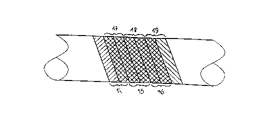
the turns abuting, the successive layers are preferably
offset in order to decrease the effect of discontinuity
brought about by the individual widths. For example, in the
case of a helical winding with abuting individual widths of
width L and a number of layers q, the position of each layer
(outward + return run) is offset by a space of width K such
that
K = _
m
where m is an integer > 1 and if possible with
m
r being an integer (see FIG 5).
The individual widths 14 ,15, 16 are the widths for the
first outward run and the individual widths 17,18 and 19 are
the widths for the second outward run.
Even though the preferred fabric is a glass fabric it is
possible, without a departing from the scope of the
invention, to employ fabrics in carbon, aramide, or high
R:\146()1~\146()6~J8 DOC - 13 novembr~ 1998 - 3/7

CA 022~860 1998-11-23
strength polyethylene. It is also possible to employ hybrid
fabrics, for example glass plus carbon.
Without departing from the invention, the fabrics can be
pre-impregnated with heat-setting resin.
Without departing from the invention, the fabrics
employed can be pre-impregnated with thermoplastic resin.
Without departing from the invention, the fabrics can be
wound at the same time as a thermoplastic film and
impregnated by melting plus compression.
Where it is desired to produce structural elements such
as piles, posts or masts which are of considerable thickness,
including cylindrical portions and having an unbalanced fiber
reinforcement along the X-X~ axis of the structural element,
the presence of significant forces tending to clamp the
composite structure against the mandrel, after
polymerization, has been observed; this phenomenon can make
it difficult to remove the element from the mandrel and can
create micro-cracking in the structure.
In order to avoid these major disadvantages, according to
the invention, a smooth layer of a compressible material is
placed on the mandrel after which the glass fabric is wound
onto this compressible mandrel.
According to the invention, the characteristics of
compressability of the material will be such that it only
shows a slight deformability under the limited force of
winding the fabric and it will absorb the contraction of the
composite structure and only transmit a slight clamping force
to the mandrel, thereby facilitating removal therefrom. The
material chosen should have a low coefficient of friction.
According to the invention, the material is preferably a
closed-cell polyethylene foam with a smooth polished skin.
Without departing from the invention, another material
having the above characteristics can be used, for example a
flexible polyurethane foam.
R~\14hûO\14(~()(.USDOC-13novembrel998-4/7

CA 022~860 1998-11-23
According to the invention, in order to facilitate
removal from the mandrel and preserve the internal surface
state of the tube, the foam should be coated with a terpane
film.
In the presence of flexural forces operating in a
priviledged radial direction, oblong-shaped tubes are
provided (see FIG 6). This type of tube can for example be
employed in the construction of breakwaters.
Without departing from the invention, the tube can have a
sandwich structure (see FIG 7) constituted by two concentric
tubes 20, 21 obtained by means of the invention and separated
by a wall 22 in a material which is rigid in compression such
as a rigid foam, a honeycomb structure, balsa, and so on.
This makes it possible to make the tubes lighter and improves
rigidity.
Without departing from the invention, in order to improve
rigidity in the presence of bending forces acting along a
preferred axis, the inner tube can be cylindrical and the
outer tube oblong.
R \ 1460()\1 4606US D0~ - 13 nov~mbre 1998 - S/7

Dessin représentatif
Une figure unique qui représente un dessin illustrant l'invention.
États administratifs

2024-08-01 : Dans le cadre de la transition vers les Brevets de nouvelle génération (BNG), la base de données sur les brevets canadiens (BDBC) contient désormais un Historique d'événement plus détaillé, qui reproduit le Journal des événements de notre nouvelle solution interne.

Veuillez noter que les événements débutant par « Inactive : » se réfèrent à des événements qui ne sont plus utilisés dans notre nouvelle solution interne.

Pour une meilleure compréhension de l'état de la demande ou brevet qui figure sur cette page, la rubrique Mise en garde , et les descriptions de Brevet , Historique d'événement , Taxes périodiques et Historique des paiements devraient être consultées.

Historique d'événement

Description Date
Inactive : CIB de MCD 2006-03-12
Le délai pour l'annulation est expiré 2001-05-23
Demande non rétablie avant l'échéance 2001-05-23
Réputée abandonnée - omission de répondre à un avis sur les taxes pour le maintien en état 2000-05-23
Inactive : CIB en 1re position 1999-02-05
Symbole de classement modifié 1999-02-05
Inactive : CIB attribuée 1999-02-05
Inactive : Notice - Entrée phase nat. - Pas de RE 1999-01-20
Demande reçue - PCT 1999-01-18
Demande publiée (accessible au public) 1997-11-27

Historique d'abandonnement

Date d'abandonnement Raison Date de rétablissement
2000-05-23

Taxes périodiques

Le dernier paiement a été reçu le 1998-11-23

Avis : Si le paiement en totalité n'a pas été reçu au plus tard à la date indiquée, une taxe supplémentaire peut être imposée, soit une des taxes suivantes :

  • taxe de rétablissement ;
  • taxe pour paiement en souffrance ; ou
  • taxe additionnelle pour le renversement d'une péremption réputée.

Les taxes sur les brevets sont ajustées au 1er janvier de chaque année. Les montants ci-dessus sont les montants actuels s'ils sont reçus au plus tard le 31 décembre de l'année en cours.
Veuillez vous référer à la page web des taxes sur les brevets de l'OPIC pour voir tous les montants actuels des taxes.

Historique des taxes

Type de taxes Anniversaire Échéance Date payée
TM (demande, 2e anniv.) - petite 02 1999-05-25 1998-11-23
Taxe nationale de base - petite 1998-11-23
Titulaires au dossier

Les titulaires actuels et antérieures au dossier sont affichés en ordre alphabétique.

Titulaires actuels au dossier
BERNARD CASTAGNER
Titulaires antérieures au dossier
S.O.
Les propriétaires antérieurs qui ne figurent pas dans la liste des « Propriétaires au dossier » apparaîtront dans d'autres documents au dossier.
Documents

Pour visionner les fichiers sélectionnés, entrer le code reCAPTCHA :


Pour visualiser une image, cliquer sur un lien dans la colonne description du document. Pour télécharger l'image (les images), cliquer l'une ou plusieurs cases à cocher dans la première colonne et ensuite cliquer sur le bouton "Télécharger sélection en format PDF (archive Zip)" ou le bouton "Télécharger sélection (en un fichier PDF fusionné)".

Liste des documents de brevet publiés et non publiés sur la BDBC .

Si vous avez des difficultés à accéder au contenu, veuillez communiquer avec le Centre de services à la clientèle au 1-866-997-1936, ou envoyer un courriel au Centre de service à la clientèle de l'OPIC.


Description du
Document 
Date
(aaaa-mm-jj) 
Nombre de pages   Taille de l'image (Ko) 
Abrégé 1998-11-22 1 61
Description 1998-11-22 5 203
Revendications 1998-11-22 2 46
Dessins 1998-11-22 2 46
Dessin représentatif 1999-02-09 1 10
Avis d'entree dans la phase nationale 1999-01-19 1 192
Courtoisie - Lettre d'abandon (taxe de maintien en état) 2000-06-19 1 184
PCT 1998-11-22 21 732