Note : Les descriptions sont présentées dans la langue officielle dans laquelle elles ont été soumises.
CA 02256291 1998-12-18
METHOD AND DEVICE FOR FIXATION
OF A SENSOR IN A BODILY LUMEN
FIELD OF THE INVENTION
The present invention relates generally to a method and device for fixation of
a sensor in a bodily lumen and for protection of the sensor during insertion
into a bodily
lumen.
BACKGROUND OF THE INVENTION
Sensors for the monitoring and/or recordation of various human physical,
chemical and/or physiological parameters are known in the art. U.S. Patent No.
4,485,813
describes a sensor that may be permanently implanted in a specific location
within the human
body in an implantable medical device such as a pacemaker. This sensor is used
to monitor
certain physical and/or physiological parameters of the subject in which it
has been
implanted. This sensor can be maintained in the subject for extended periods
of time to
continuously monitor information about the subject.
A severe limitation to the sensor described in U.S. Patent No. 4,485,813 is
the
limited number of possible locations in which it can be implanted due to the
requirement that
the sensor be located in a medical device such as a pacemaker and the
difficulty of fixation
independently. This limitation on the location and fixation of the sensor
limits the usefulness
of the sensor for inter-lumen applications.
Sensors used to monitor parameters within lumens are made of very thin
membranes that are highly sensitive to mechanical pressure. As a result there
is a great risk
of the sensor being damaged during insertion and or positioning. Damage to the
sensor could
result in poor performance or non-operability of the sensor. For example,
should the
membrane of a sensor break during insertion, the sensor would be rendered
inoperable. Due
to the risks associated with the procedures for the insertion of sensors,
there would be great
CA 02256291 1998-12-18
costs and risks involved should a sensor be damaged or destroyed during
insertion. Thus,
there is also a need for a device and method of protecting sensors during
insertion and
fixation.
SUMMARY OF THE PRESENT INVENTION
It is, therefore, an object of the present invention to provide a method and
device for fixation of a sensor in a bodily lumen. Through the use of such a
method and
device, remotely interrogated sensors may be fixed within bodily lumens. Such
sensors may
be used to record and/or monitor parameters such as, for example,
physiological parameters,
e.g., pressure and velocity of flow, and biochemical parameters, e.g., level
of gases and
biochemical substances in the fluid contained in the lumen.
The monitoring of conditions in lumens today dictates some level of
intervention and the fi~equency of such monitoring is limited by the relative
risk of the
required intervention. The present invention, therefore, provides a sensor
device which may
I S be implanted, either temporarily or permanently, in a lumen and
interrogated from an exterior
position, for example, the surface of the body, at any time without any
intervention or
physical intrusion.
The present invention provides a method and device for the fixation of such
sensors in specific desired locations and/or preferred positions in the lumen.
Such fixation of
the sensors may be achieved at the time of any required surgical intervention
or
independently by catheterization. Furthermore, the sensor may be connected to
the repair
device, e.g., the stitches of a bypass, an aneurismal repair device, a stmt,
etc., or mounted on
its own dedicated fixation device.
A sensor may be fixed inside a lumen by any number of means, including
2
CA 02256291 1998-12-18
directly attaching the sensor in place, for example, by including holes in the
sensor, e.g.,
around its periphery, and attaching the sensor to the stitches of a bypass
during surgery, or
through the use of a surgical adhesive. A sensor may also be positioned inside
a lumen using
a carrier or support (of any shape and size) which may be part of, or coupled
to a repair
device, e.g., a stmt or aneurismal correction device which holds the sensor in
place adjacent
to or near the repair device. Additionally, a sensor may be positioned inside
a lumen using a
dedicated device, e.g., an anchoring ring, which is held within a lumen and
fixed in place, for
example, by expansion with a catheter balloon. The anchoring ring does not
necessarily have
to be circular in shape, but may instead be oval or any other shape best
suited for the location
where placed. Additionally, the anchoring ring may have a separate carrier or
support to hold
the sensor. The carrier or support may be any shape or size, including, for
example, circular,
square, rectangular, diamond shaped, linear with or without a bent or curved
end, etc, and it
may be constructed as only a border or as a solid piece of material.
Multiple sensors may be attached to a Garner or carriers, for example, two
sensors with one placed on each side of a stent, or two sensors attached at
both connections
of a bypass section, e.g., one sensor at the entrance to an aneurismal sleeve
and one at the
outside of the sleeve to monitor for a possible leak around the sleeve.
Additionally, a sensor
may have multiple repair devices or dedicated devices supporting it within a
lumen, either
with or without a Garner, for example, a sensor supported between two
anchoring rings.
A sensor may be supported by or connected to a carrier, for example, by
providing a groove-like depressions) or notch-like depressions) in the sensor
into which a
portions) of the carrier may be inserted, or the sensor may be configured such
that a
portions) of the sensor, for example, a lip-like extensions) or protrusion(s),
may extend
beyond the dimensions of the carrier to be supported thereby. Additionally,
the sensor may
3
CA 02256291 1998-12-18
be attached to the carrier, for example, by welding and/or glueing or any
combinations of the
above.
After a sensor is fixed within a lumen, for example, during an intervention
procedure such as aneurismal device implantation, PTCA, coronary bypass
surgery, etc., it
may thereafter be monitored periodically to track any of a variety of
parameters or to assess
the effectiveness of the procedure that was performed. For example, the sensor
may be
monitored periodically to assess the long term progress or deterioration of
the corrective
effect, and the progress of relevant symptoms of a disease.
Multiple sensors may be implanted and may be monitored individually or
simultaneously to derive gradients along a lumen and across a repair device or
section. Such
sensors may be fixed in any number of positions within a lumen, for example,
on both sides
of a lesion treated by PTCA with or without a stmt, on both sides of a bypass
section, and
before, after and around an aneurismal repair device, etc.
The present invention also provides for a device and method for the protection
of sensors during insertion. In order to preserve sensors during insertion and
remove the risk
of damage to or destruction of sensors during an insertion or positioning
procedure, sensors
may be coated with a protective layer which is soluble in an aqueous solution,
and which
disappears immediately or soon after deployment of the sensor in the body. The
material
used for, thickness of, and hardness of the coating may vary, for example,
depending on the
location of the sensor, the type of sensor, protection level sought, and rate
of dissolution
desired.
The fixation device may be constructed by first creating a flat version of the
desired pattern for the fixation device, for example, from a piece of thin
stainless steel sheet
metal or some other material, e.g., any metal, non-metallic or bioabsorbable
material. The
4
CA 02256291 1998-12-18
flat pattern can be produced through any suitable technique, such as etching
the design into
the sheet metal, by cutting with a very fine laser, or by any other technique.
Once the material has been cut, it is deformed so as to cause its edges to
meet.
To create a fixation device from a flat, metal pattern, the flat metal is
rolled until the edges
meet. The portion which holds the sensor may be located along the
circumference of the
fixation device, may extend perpendicular to the cross-section of the ring
formed or may
extend in some other manner from the ring formed by the fixation device. The
locations
where edges meet are joined together, such as by spot welding. Afterwards, the
fixation
device is polished, either mechanically or electrochemically.
BRIEF DESCRIPTION OF THE DRAWINGS
The present invention will be understood and appreciated more fully from the
following detailed description taken in conjunction with the drawings in
which:
Fig. 1 A is a drawing of a first fixation device for a sensor according to a
preferred embodiment of the present invention;
Fig. 1 B is an illustration of a method for fixation of the sensor of Fig. 1 A
within a lumen according to a preferred embodiment of the present invention;
Figs. 2A and 2B, show illustrations of a second fixation device for a sensor
before expansion and after expansion, respectively, according to a preferred
embodiment of
the present invention.
Figs. 3A and 3B, show illustrations of a third fixation device for a sensor
before expansion and after expansion, respectively, according to a preferred
embodiment of
the present invention.
Fig. 4, illustrates a second method for fixation of a sensor within a lumen
5
CA 02256291 1998-12-18
using the third fixation device shown in Figs. 3A and 3B, according to a
preferred
embodiment of the present invention.
Fig. 5, shows an illustration of a mask for etching of a flat design of the
fixation device of Figs. 3A and 3B, according to a preferred embodiment of the
present
invention.
Fig. 6, shows an illustration of a mask for etching of a flat design of the
fixation device of Figs. 2A and 2B, according to a preferred embodiment of the
present
invention.
Figs. 7, shows a fourth fixation device for a sensor before expansion,
according to a preferred embodiment of the present invention.
Fig. 8, shows an illustration of a mask for etching of a flat design of the
fixation device of Fig. 7, according to a preferred embodiment of the present
invention.
Figs. 9A and 9B, show an enlarged side view of a cross section of the sensor
support from Fig. 3A along the line formed between points a' and a' according
to two
different embodiments of the present invention.
DETAILED DESCRIPTION OF A PREFERRED EMBODIMENT
Reference is now made to Figs. 1 A and 1 B, which illustrate a first fixation
device for a sensor and a first method for fixation of a sensor within a
lumen, respectively,
according to a preferred embodiment of the present invention.
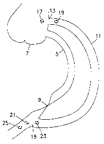
In Fig. 1 A, there is shown a sensor 1 having two holes 3 in its periphery for
attachment to sutures within a lumen. In Fig. 1 B, there is shown a coronary
artery 5 starting
at the Aorta 7 and having an occlusion 9. A bypass 11 is connected between the
Aorta at
point 13 and at point 15 beyond the occlusion 9. Sensor 1 is placed either at
the proximal
6
CA 02256291 1998-12-18
ostium 17 or at the proximal part of the bypass 19. Alternatively, sensor 1
may be placed at
the distal ostium 21, at the distal part before the distal ostium 23, or at
the distal part after the
distal ostium 25. Any number of sensors may be used, and they may be placed in
any
combination of the above positions or any other position desired. The sensor 1
is fixed in
place using the two holes 3 for attachment to the sutures. Alternatively, the
sensor 1 may be
fixed in place using surgical adhesive or a surgical staple(s).
Referring now to Figs. 2A and 2B, there are shown a second fixation device
for a sensor before expansion and after expansion, respectively, according to
a preferred
embodiment of the present invention.
In Fig. 2A, there is shown a stent 30 in a non-expanded state with a first
sensor support 32 and a second sensor support 34. Alternatively, the stmt 30
may include
only one or more than two sensor supports. For example, a third sensor support
may be
located opposite the first sensor support 32. In Fig. 2B, the stmt 30 from
Fig. 2A is shown in
its expanded state. Expansion may be accomplished, for example, by balloon
catheterization
or some other procedure. To fix a sensor within a lumen, the stmt 30 is
positioned as it
normally would be during any medical procedure in which a stmt is used. Prior
to
expansion, and either prior to or after insertion of the stmt 30 into the
lumen, a sensor is
placed in, placed on or attached to the first sensor support 32 and/or the
second sensor
support 34. The stent 30 is then either expanded, or inserted into the lumen
and then
expanded. The same procedure may be used to fix any number of sensors within a
lumen,
with the additional step of placing each sensor either in or on, or attaching
each sensor to its
corresponding sensor support.
Referring now to Figs. 3A and 3B, there are shown a third fixation device for
a sensor before expansion and after expansion, respectively, according to a
preferred
7
CA 02256291 1998-12-18
embodiment of the present invention.
In Fig. 3A, there is shown a fixation device 40 in the form of an anchoring
ring 42, in a non-expanded state coupled to a sensor support 44. The fixation
device 40 may
be formed of any malleable material which does not revert automatically to its
original shape
after being expanded. The anchoring ring 42 is made up of a plurality of
elliptical sections
46 connected one to the other at the middle of each of their long portions 48
to form a ring.
The sensor support 44 is connected to one of the elliptical sections 46 at a
short portion 49,
and perpendicular to a cross-section of the anchoring ring 42 forming a
circular plane. The
sensor support 44 is formed in the shape of a diamond, but can be any shape
desired.
Additionally, there may be multiple sensor supports attached to the anchoring
ring 42.
Alternatively, the anchoring ring 42 may be made of a single sinusoidal ring,
with one or
more sensor supports attached to the peaks, since it does not serve any
support fimction for
the lumen.
Fig. 3B shows the fixation device 40 of Fig. 3A in an expanded state. To fix a
sensor within a lumen, the fixation device 40 is positioned within the lumen,
for example,
during an intervention procedure, and expanded, for example, by balloon
catheterization or
some other procedure. Prior to expansion, and either prior to or after
insertion of the fixation
device 40 into the lumen, the sensor is placed in, placed on or attached to
the sensor support
42. The fixation device 40 is then either expanded, or inserted into the lumen
and then
expanded. The same procedure may be used to fix multiple sensors within a
lumen, with the
additional step of placing each sensor either in or on, or attaching each
sensor to a
corresponding sensor support.
Referring now to Fig. 4, which illustrates a second method for fixation of a
sensor within a lumen using the third fixation device shown in Figs. 3A and
3B, according to
8
CA 02256291 1998-12-18
a preferred embodiment of the present invention. As illustrated in Fig. 1 B, a
coronary artery
starting at the Aorta 7 and having an occlusion 9 is fitted with a bypass 11
which is
connected between the Aorta at point 13 and at point 15 beyond the occlusion
9. Sensor 50,
which is carried by the sensor support 44 coupled to the anchoring ring 42 of
Figs. 3A and
5 3B, is placed either at the proximal part of the bypass 19, at the distal
ostium 21, at the distal
part before the distal ostium 23, or at the distal part after the distal
ostium 25. Any number of
sensors may be used, and they may be placed in any combination of the above
positions or
any other position desired in which an anchoring ring can be used. The sensor
50 is fixed in
place by expansion using balloon catheterization.
Referring now to Fig. 5, there is shown an illustration of a mask for etching
of
a flat design of the fixation device of Figs. 3A and 3B, according to a
preferred embodiment
of the present invention. A mask 52 is created for etching a flat design of a
fixation device.
The flat design is then etched onto a piece of thin sheet metal or some other
malleable
material. The flat design is next cut from the sheet metal using, for example,
a fine laser.
The cut flat design is then polished and bent into a circular (or other)
shape. Points 54 and 56
show the locations where the flat design is coupled, for example, by welding
after it is bent.
The welding creates an anchoring ring. Sensor support 58 is positioned
approximately at the
midpoint of the mask 52, but may alternatively be located at any other
position.
Additionally, there may be multiple sensor supports, for example, located at
both sides of the
fixation device design.
Referring now to Fig. 6, there is shown an illustration of a mask for etching
of
a flat design of the fixation device of Figs. 2A and 2B, according to a
preferred embodiment
of the present invention. A mask 60 is created for etching a flat design of a
stent. The flat
design is then etched onto a piece of thin sheet metal or some other malleable
material. The
9
CA 02256291 1998-12-18
flat design is next cut finm the sheet metal using, for example, a fine laser.
The cut flat
design is then polished and bent into a circular (or other) shape and coupled,
for example, by
welding after it is bent. Sensor support 62 is positioned approximately at the
midpoint of the
mask 60, but may alternatively be located at any other position. Additionally,
there may be
multiple sensor supports, for example, located at both sides of the stent
design.
Referring now to Fig. 7, there is shown a fourth fixation device for a sensor
before expansion, according to a preferred embodiment of the present
invention. A fixation
device 70 in the form of a dual anchoring ring comprises a first ring 72 and a
second ring 74,
in a non-expanded state, with a sensor support 76 positioned between the two
rings 72, 74.
The fixation device 70 may be formed of any malleable material which does not
revert
automatically to its original shape after being expanded. The fixation device
70 is made up
of a plurality of sections 78 connected one to the other to form two anchoring
rings 72, 74. A
sensor support 76 is connected to one of the sections 78 of each anchoring
ring 72, 74
perpendicular to a cross-section of each of the rings 72, 74 forming a
circular plane, and is
positioned between the two rings 72, 74. The sensor support is formed in the
shape of a
diamond, but can be any shape desired. Additionally, there may be multiple
sensor supports
attached to the fixation device 70. Alternatively, the fixation device 70 may
be made of two
single sinusoidal rings, with one or more sensor supports attached to the
peaks, since it does
not serve any support function for the lumen. The fixation device 70 may
alternatively be
made of two stents, one on each side of a sensor support, or having multiple
sensor supports
attached thereto.
Referring now to Fig. 8, there is shown an illustration of a mask for etching
of
a flat design of the fixation device of Fig. 7, according to a preferred
embodiment of the
present invention. A mask 80 is created for etching a flat design of a
fixation device. The
CA 02256291 1998-12-18
flat design is then etched onto a piece of thin sheet metal or some other
malleable material.
The flat design is next cut from the sheet metal using, for example, a fine
laser. The cut flat
design is then polished and bent into a circular (or other) shape. Points 82
and 83, and points
84 and 85 show the respective locations where the flat design is coupled, for
example, by
welding after it is bent. The welding creates two anchoring rings. Sensor
support 87 is
positioned approximately at the midpoint of the mask 80, but may alternatively
be located at
any other position. Additionally, there may be multiple sensor supports, for
example, located
at both sides of the fixation device design.
Referring now to Figs. 9A and 9B, there is shown an enlarged side view of a
cross section of the sensor support from Fig. 3A along the line formed between
points a' and
a'. As shown in Fig. 9A, a groove 90 is formed in two portions of the
periphery of sensor 92,
for example, by cutting with a wire saw, by etching, by laser cutting, etc.,
and the sensor 92 is
then inserted into the sensor support 44 such that two portions of the sensor
support 44 are
positioned within the groove 90 providing support for the sensor 92.
Alternatively, instead of
the grooves, two notches may be formed in the periphery of the sensor 92 in
which the two
portions of the sensor support 44 may be positioned.
As shown in Fig. 9B, sensor 94 is formed with a lip 96 around its upper edge
98. Sensor 94 may instead be formed with one or more protrusions along its
upper edge 98.
Alternatively, the lip or protrusions) may be located on the bottom or at any
other position
on the sensor. The sensor 94 is coupled to the sensor support 44, for example,
by glueing,
welding, soldering, etc., the lip 96 or protrusions) to an edge or portion 99
of the sensor
support. Alternatively, the sensor 94 may be placed on the sensor support 44
and supported
by the lip 96 or by the protrusion(s).
Due to the sensitivity of the sensors that are used for monitoring, which have
11
CA 02256291 1998-12-18
very thin membranes that are extremely sensitive to mechanical pressure, a
coating may be
placed on the sensors to protect them from damage and/or destruction during
deployment.
The coating may be made firm a material that is soluble in an aqueous
solution, and should
dissolve immediately or soon after deployment of the sensor. The material
used, the
thickness of the coating and the hardness of the coating will depend to a
large extent on the
location of the sensor, the type of sensor, and a variety of other factors
including the
physiology involved, the parameters being measured, and the desired speed of
deployment.
A first example of a coating is a composition comprising solidified sugar
syrup made of approximately equal amounts of glucose and sucrose. The
proportions of
glucose and sucrose may be varied, however, depending on the application.
A second example of a coating is a composition comprising Hydroxy Propyl
Methyl Cellulose, Hydroxy Propyl Cellulose and Colloidal Silicone Dioxide, all
finely
ground and mixed in water, which is used for coating pills and is commercially
available as
Opadry-Oy-34817 from Colorcon Ltd., Italy.
Other materials may be used as a protective coating for a sensor. The
protective coating may be made from any other substance which is hard or thick
enough to
protect the sensor from damage during insertion, dissolves immediately or soon
after
insertion and is biocompatible in the intended location of deployment in the
body.
A sensor may be coated by any available method for coating objects including,
for example, spraying the coating on the send, dipping the sensor in a liquid
bath, pouring
or dripping the coating onto the sensor, painting the coating onto the sensor,
etc.
Additionally, the coating may cover only the membrane of the sensor or it may
cover a larger
portion of the sensor or the entire sensor.
12