Note : Les descriptions sont présentées dans la langue officielle dans laquelle elles ont été soumises.
CA 0225690~ 1998-12-22
PATCH PANEL WITH RETRACTABLE PATCH CORD
The invention relates to a patch panel for connecting electrical
equipment used for telecommunications and data applications, and more
particularly to a panel having a retractable cord for connecting electrical
equipment over a range of separation distances.
Patch panels provide a structure for changing connections in
telecommunications and data applications. In local-area-network applications,
patch panels may be provided between a data hub and a workstation.
Connection links may be run from the workstation to the patch panel, and from
the data hub to the patch panel. The patch panel allows for convenient initial
10 connections and allows for an efficient reorientation and reorganization of the
connections between the workstation and the data hub.
Patch panels are known which provide a modular jack interface,
particularly with modular jack outlets. The outlets are preferably provided withlabels such that a user (e.g. an information system manager) can reorder and
15 reconfigure the various workstation connections to a network data hub. Similar
arrangements may be used for telephone systems.
Recent improvements to patch panels focus on the modular jack
interface, to improve the electrical performance of the patch panel. This is
especially necessary for establishing an electrical link for high-speed data
20 transmission. For this purpose, cabling (wires) have been employed which are
also suitable for high-speed transmission. Connection elements (jack plugs,
etc.) have also been developed for high-speed transmission.
An important feature of a patch panel configuration is its ability to
adapt a system to changes as to the various electrical links (such as changes
25 in connections). Because local-area-network physical arrangements are often
changed, there is a need to keep cabling on hand for various possible physical
connections. This can be especially problematic when new data hubs and
similar equipment are added which require cabling of various different lengths
extending from the patch panel to the hub (or between patch panels). The task
,, _ , ,
CA 022~690~ 1998-12-22
of purchasing, and maintaining on hand, various different lengths of high-
performance cabling has become quite problematic and results in extremely
high costs.
The invention is based on the technical problem, therefore, of
providing a patch panel for telecommunications and data applications which
enables flexible adaptation to changing links, with Jittle furnishing.
According to the invention a patch panel is provided comprising a
patch panei housing, a first electrical connector means and a second electrical
connector means extending from the patch panel housing and an electrical
10 interconnection means for connecting the first electrical connector means andthe second electrical connector means. The interconnection means maintains
electrical connection between the first electrical connector means and the
second electrical connector means while allowing the first connector means to
be moved both toward and away from the housing, for adjusting a position of
15 the first electrical connector means relative to the housing. As a result, when
the positioning of the external devices is altered, the position of the patch panel
housing itself does not have to be altered. In particular, no new connection
lines have to be used; rather, the first connection means has only to be moved
to the new position.
The electrical interconnection means comprises an electrically-
conductive wire extending uninterrupted between the first connector and the
second connector. At least one spool is preferably provided, with a first wire
portion of the wire being wrapped around a first spool part and a second wire
portion of the wire being wrapped around a second spool part. The first portion
25 of the wire is disposed so as to be extendable from (paid out from) the firstspool part for changing a position of the first connector means relative to the
housing.
The patch panel of the invention provides significant advantages.
The structure including the single uninterrupted integral wire extending from the
30 first connection means to the second connection means provides superb
performance. The connection allows for high-speed transmission over the
CA 022~690~ 1998-12-22
length established by the patch panel (between the first connection means and
second connection means). The first connection means is able to be moved
away from and back toward the patch panel without storage problems as to the
length of wire which remains in the patch panel, and without a moving
5 connection such as an electrical connection based on two moving parts or slip
rings. This is achieved by the novel storage of the second wire portion in the
second spool part or in a spool storage region. The extension of the first wire
portion and the retraction of the first wire portion occurs without significant
physical twisting or harm to the wire, thereby ensuring the integrity of the
10 electrical link and providing the capability for high-speed (high-frequency)
transmission.
The second wire portion is preferably approximately one half the
length of the first wire portion. The electrically-conductive wire is an integral,
uninterrupted wire, with a transition between the first wire portion and the
15 second wire portion preferably occurring as the wire passes through a center of
the spool. As the first wire portion is paid out, the second wire portion remains
in the second spool part. This second spool part forms the storage region.
A cartridge case is preferably provided supporting the spool. The
cartridge case is positioned within the housing and can be removed from the
20 housing to access the spool and the wire. This allows the user to change the
wire if the wire is not providing the proper performance. The cartridge
preferably includes an additional spool mounted therein. The second spool has
an additional first connection means, an additional second connection means
and an additional electrical interconnection means connected to the first
25 connection means and the second connection means. A plurality of cartridges
are preferably disposed in the housing.
Each spool is preferably connected to a spring means for exerting
a spring force on the spool for maintaining the first wire length in a retractedstate. A ratchet means is preferably provided for fixing a rotational position of
30 the spool.
CA 022~690~ 1998-12-22
By disposing the second wire portion in the spool storage space
and wound in the same direction as the winding of the first wire portion, the
second wire portion unwinds in a first rotational direction within the storage
space and subsequently begins winding again in a second rotational direction
as the first wire portion is moved beyond half of its full extension toward the full
extension. This arrangement allows the second wire portion to be
approximately half the length of the first wire portion such that less wire is
stored than is paid out of the patch panel. The orientation and provision of thesecond wire portion such that it unwinds in a manner to extend outwardly toward
10 a periphery of the spool storage space before winding on the spool storage
space core, in a direction opposite to its original winding direction, provides an
orderly transition from a first winding direction to a second winding direction,providing a smooth payout of the first wire portion without problems as to the
second wire portion. That is, there is no problem with the portion of the wire
15 extending from the first wire portion to the preferably fixed second connection
means.
A preferred embodiment of the invention will next be described
utilizing the accompany drawings, in which:
Figure 1 is a schematic view of the connection of the patch panel
20 of the invention to various electrical equipment;
Figure 2 is a perspective view of the patch panel according to the
invention, illustrating the housing and cartridges with extendable wires;
Figure 3 is a perspective view of a cartridge of the patch panel;
Figure 4 is a perspective exploded view of the cartridge of Figure
25 3;
Figure 5 is a perspective exploded view of a spool of the patch
panel, illustrating spool halves and a spring motor;
Figure 6 is a schematic cross-sectional view of a cartridge
according to the invention;
Figure 7 is a side view of a cartridge, illustrating the storage spool
half with the extendable wire in a fully-extended position;
CA 022~690~ 1998-12-22
.
Figure 8 is a side view of a cartridge showing the stored wire
portion, with the extendable wire portion being extended almost 50% of its full
extension length, with the stored portion of the wire starting to extend outwardly
toward the periphery of the spool storage space prior to winding itself in a
direction opposite to its original winding direction; and,
Figure 9 is a side view of a cartridge showing the storage wire
portion in a position after the wire has been extended out of the patch panel bya first distance.
Referring to the drawings in particular, the invention comprises a
patch panel generally designated 8. The patch panel includes a housing 10 and
a plurality of first electrical connectors 12 and a plurality of second electrical
connectors 14 (see Figure 6). The patch panel 8 further includes a physical and
electrical interconnection means 16. The interconnection means 16 provides
a connection line or link between each first electrical connector 12 and each
second electrical connector 14.
The interconnection means 16 is formed from a continuous
uninterrupted wire 18. Preferably the wire 18 includes a wire formed with at
least one integral continuous wire strand. The wire 18 includes an extendable
wire portion 18' and a stored wire portion 18" (see Figure 4).
The patch panel 8 of the invention may be used in a situation as
shown in Figure 1. A plurality of data hubs 20 may be provided. A distance
(L1, L2, L3, etc.) between the patch panel and the devices to be connected
such as the data hubs 20 is different for each device.
If it is necessary to rearrange the connections between the patch
panel 8 and the data hubs 20, the wire portion 18' may be extended as needed.
Various lengths of patch cords are not needed for making the various
connections. The invention provides a retractable electrical interconnection
means, namely the electrical interconnection means 16 between the first
electrical connector 12 and a second electrical connector 14. With this
structure, no patch cords are necessary at all. The electrical connection
between the first electrical connector 12 and the second electrical connector 14
CA 022~690~ 1998-12-22
is via an extendable/retractable cord, namely the extendable wire portion 18' ofthe uninterrupted wire 18.
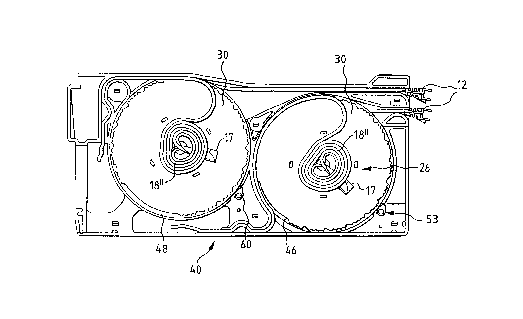
Figure 2 is a representation of the patch panel 8 with a housing
generally designated 10. The patch panel 8 includes a front face 22 with a
5 plurality of the first electrical connectors 12. Additionally, the patch panel 8
includes a rear face 24. The rear face 24 also has a plurality of the electricalconnectors, namely, the second electrical connectors 14 (see Figure 6). The
housing 10 supports cassettes or cable cartridges 40. Each cartridge 40 has
two first electrical connectors 12 and two second electrical connectors 14.
The invention provides a plurality of cartridges 40 which each
support two spools 30. Each cartridge 40 preferably includes a wire
management element 42 on a front face 22 and a wire management element
44 on the rear face 24. The cartridge 40 is provided to be extractable from the
shell of the housing 10 as shown in Figure 2. In the case of a problem with any
of the lines, a cartridge 40 is removed from the shell of the housing 10, allowing
the spool 30 to be removed from the cartridge. The wire 18 on the spool 30
may be replaced, or a new spool 30 with a wire 18 may be positioned back in
the cartridge, with the first contact 12 and the second contact 14 being disposed
at the front face 22 and the rear face 24, respectively. This arrangement
provides a practical mechanism for replacing lines which do not function or do
not perform to the proper level.
Figure 3 shows the cartridge 40 removed from the housing 10. A
front plate 41 covers the spools 30.
As can be seen in Figure 4, each cartridge 40 includes a support
structure 43 with a front spool receiving area 46 as well as a rear spool
receiving area 48. The two first electrical connectors 12, the two second
electrical connectors 14 and the associated wires 18 are provided with each
cartridge 40. This arrangement provides for a connector density which is similarto standard patch panels, namely rows of two connectors.
Each spool 30 is connected to the cartridge 40, with an interior
surface of its core 31 being supported via a bearing element 50. The bearing
CA 022~690~ 1998-12-22
element 50 is preferably merely a cylindrical element for supporting the spool
30 in rotation. Additionally, a spring means 17 (see Figure 5) in the form of a
spring motor 52 is provided for assisting in retracting the wire portion 18', after
it has been extended. The spring 52 provides a rotational bias whereby, as the
wire portion 18' is paid out, there is a force exerted on the wire for retracting the
wire. To avoid placing the wire under too much stress, a ratchet means 53 is
provided associated with both the front spool receiving region 46 and the rear
spool receiving region 48. Each ratchet means includes teeth 56 provided on
each spool 30 and a pawl element 60 connected to a spring 61. The pawl
10 element 60 can be moved into engagement with the gear teeth of a
transmission gear or gear teeth 56, thereby holding the spool 30 in position andalso eliminating the rotational biasing force which otherwise would be applied
to the wire 18.
The electrical interconnection means 16 according to the invention
15 is based on a single continuous line (wire) 18 which extends from the first
electrical connector 12 to the second electrical connector 14. This
interconnection means 16 is provided in the form of a wire 18 which is stored
in the patch panel 8 until it is used. During use, the wire portion 18' extends out
of the patch panel.
The spools 30 pay out the connection wire portion 18' and store
the connection wire portion 18". The connection wire portion 18' may be
retracted to position it for storage. A feeding and storage means is formed fromthe spool generally designated 30, a spring means 17 and the ratchet means
(including pawl element 60, teeth 56 and spring 61). As can be seen from
25 Figure 6, each spool 30 includes a payout spool half 32 and a storage spool
half 34. The payout spool half 32 provides the space for storing the extendable
wire portion 18' which is to be paid out, to the extent necessary to connect thefirst connection means 12. The other half of the wire 18, the stored portion 18",
is disposed in the storage spool half 34. This stored portion 18" in the storage30 spool half 34 is approximately equal to one half of the length of the extendable
portion 18' (one half of the maximum amount of wire 18 which can be extended
CA 022~690~ 1998-12-22
out of the patch cord 10). As the wire 18 is a single, continuous integral wire
extending from the first connector 12 to the second connector 14, there is a
transition portion 18t between the wire portions 18' and 18" in the core 31 of the
spool 30. Further, the length of the wire from the connector 14 to the spool
storage spool half 34 is preferably constant (does not change). This provides
a significant advantage according to the invention that a single uninterrupted
electrical line is provided from the first connector 12 to the second connector 14.
This materially enhances the performance of the device and removes problems
with regard to transmission of an electrical signal between moving parts.
10 However, this results in the significant requirement that the maximum payout
length of extendable wire 18' is limited by the storage of the remaining portionof the wire 18.
The connector 14 is directly connected to the wire 18 which is fed
into the storage spool half 34 and crosses over into the payout spool half 32.
15 The distance between the crossover point and the point at which the wire 18t
exits the spool 30 substantially corresponds to the distance between the
crossover point and the first connection element 12. The same relationship is
provided with regard to the rear of spool 30 and associated front first connecting
element 12, rear first connecting element 14 and interconnection wire 18.
The invention provides a unitary or single wire connecting the first
wire connection element and the second wire connection element. In order to
use a single uninterrupted continuous wire 18, to provide for the wire
interconnection means 16, there must be an amount of wire 18" stored on the
spool in the storage spool half 34 which is less than or equal to the amount of
25 wire stored on the spool in the payout spool half 32, when the wire is fully
retracted. Using an equal length for storage could lower the performance of the
patch panel. This could also be problematic with regard to the physical storage
of the portion of the wire 18 which remains fully within the patch panel at all
times.
According to the invention, a wrapping technique is used for the
stored portion of the wire 18". This allows only approximately half of the wire
CA 022~690~ 1998-12-22
to be deployed on the storage spool half 34 as compared to the payout spool
half 32. The wire 18' which is paid out from the payout spool half 32 is about
twice the length of the wire 18", to be deployed within the storage spool half 34.
When the wire 18 is approximately extended a half of its maximum
5 distance, a full amount of stored wire 18" has been unwound in the storage
spool half 34 in a first rotational direction. As the wire 18 is further extended
from the patch panel, the stored part of the wire 18 reverses itself from being
unwound in a clockwise direction (for example) to being wound in a
counterclockwise direction.
Figure 7 shows the state of the stored wire portion 18" and the
storage spool half 34 when the extendable part of the wire portion 18' is in a
retracted position. As can be seen, the stored wire portion 18" is fully wound.
Rotation in a clockwise direction, and extension of the wire portion 18' from the
payout spool half 32, will result in the stored wire portion 18" being unwound,
15 as shown in Figure 8. The distance between the second wire connection
element 14 and the periphery of the spool is fixed such that the stored wire
portion 18" unwinds within the storage spool half 34 but is maintained within that
spool half. In Figure 8, the wire 18' is almost 50% extracted from the payout
spool half 32. The wire portion 18" within the storage spool half 34 is almost
20 fully unwound.
Figure 9 shows the extendable wire portion 18' fully extended from
the payout spool half 32. In this fully extended position, the stored wire portion
18" in the storage spool half 34 is fully wound about the spool core 31 (center)of the storage spool half 34 in a second rotational direction. At this point, the
25 extendable wire portion 18' cannot be further extended from the payout spool
half 32.
The ratchet means 53 allows the wire 18 to be extended to any
distance between the maximum extension length and the minimum extension
length and then held in that position. This is convenient as the spring force of30 the spring means 17 is no longer applied to the spool when the pawl element
60 is engaged with the teeth 56 and therefore the wire 18 is no longer strained
CA 022~690~ 1998-12-22
by the force of the spring motor 52. This is also a practical arrangement such
that the technician rewiring or wiring using the patch panel of the invention can
extend the wire to the length needed without the wire snapping back into the
retracted position.
As the wire 18' returns from its fully-extended position back to its
retracted position, the portion of the wire in the storage spool half 34, shown in
Figure 9, unwinds as the spool rotates in a counterclockwise direction. Again
the unwinding causes the wire to be pushed out toward the periphery of the
storage spool half 34 until the wire is retracted beyond about 50% of its
10 extended state. At this point the wire begins winding again as the spool
continues to turn in the counterclockwise direction. This eventually results in a
return to the state shown in Figure 7.
While specific embodiments of the invention have been shown and
described in detail to illustrate the application of the principles of the invention,
15 it will be understood that the invention may be embodied otherwise without
departing from such principles.