Note : Les descriptions sont présentées dans la langue officielle dans laquelle elles ont été soumises.
CA 022~810~ 1998-12-08
- WO 97/48903 PCT/US97/10636
IMPROVED T~ME DELAY IGN~l~ON GIRCUlT
FOR AN INTERNAL COMBUST~ON ENGINE
5 CROSS-REFERENCES TO REI~TED APPLICATIONS
This application claims the benefit of U.S. provisional application serial
number 60/020,032, filed June 21, 1996.
Attention is directed to United States patent appliç~tion serial no.
08/507,664, filed July 25, 1995.
BACKGROUND OF THE INVENTION
The invention relates to an internal combustion engine, and particularly to
an ignition timing circuit for an internal combustion engine.
Spark-ignited internal combustion engines require a spark at the spark plug
in order to ignite the fuel and air ~ lu~e in the cylinder of the engine. The
timing of the combustion event is critical in the operation of the internal
combustion engine. Particularly, the timing of the combustion event controls thespeed and acceleration of the engine as well as the efficiency with which the fuel
20 in the cylinder is burned. Various methods of timing the combustion event areknown. In particular, it is generally known to make use of various engine
operating parameters to time the combustion event. Such parameters may
inrhlde cr~nl~ch~ft angle, engine temperature and/or cylinder ples~u,e.
25 SUMMARY OF THE INVENTION
In the case of an internal combustion engine utili7ing fuel injectors, the
air/fuel l~ixlllre is ~tomi7ed into a "stratified" fuel/air cloud that "floats" from the
injector nozzle in the cylinder toward the spark gap at the spark plug. If the
30 ignition spark jumps the spark gap before the fuel/air cloud reaches the spark
gap, the fuel/air cloud will not be completely burned. In order to assure that
complete combustion of the stratified fuel/air cloud is attained, it is necessary to
time the ignition spark for the precise moment when the fuel/air cloud reaches
the spark gap.
.~.. ~ .. ~
CA 022~810~ 1998-12-08
- WO 97/48903 PCT/US97/10636
-2-
Accordingly, this invention provides an absolute time delay ignition circuit
for an internal combustion engine. The time delay ignition circuit bases the
timing of the ignition spark on the el~psed time from the fuel injector event.
That is, the electronic control unit of the engine generates a signal c~using
S injection of fuel by the fuel injector and subsequently generates a signal c~llcing
an ignition spark based on an absolute period of elapsed time measured from the
injection signal. The electronic control unit can generate the time delay based
upon either a fixed calibrated time period, a predetermined time period stored in
a memory based look-up table, or a time period calc~ te~l from a software based
10 algorithm that evaluates various parameters such as temperature, pressure, etc.
In one embodiment, the engine is operated with time-based ignition at low
speeds, and is operated with crank-angle-based ignition at high speeds, i.e., the
change from time-based ignition to crank-angle-based ignition is based solely onengine speed. In another embodim~-nt, the engine is operated with time-based
lS ignition at low engine loads (as measured by throttle position), and is operated
with crank-angle-based ignition at high engine loads, i.e., the change from time-
based ignition to crank-angle-based ignition is based solely on engine loads. Inanother embodim~nt, the engine is operated with time-based i~nition at low loadsand low speed, and is operated with crank-angle-based iglution at either high
20 loads or high speeds, i.e., the change from time-based ignition to crank-angle-
based ignition is based on both the engine speed and engine load.
The invention also provides an internal combustion engine assembly
comprising: an internal combustion engine inclll-ling an engine block having at
least one cylinder; a piston mounted within the cylinder for reciprocal movement25 in the cylinder; a fuel injector for injecting fuel into the cylinder; and circuit
means for generating an injection control signal indicative of a fuel injection
event and for generating a spark in the cylinder a predetermined amount of time
after generation of the injection control signal.
The invention also provides an internal combustion engine assembly
30 co~ h~g; an internal combustion engine in~ rling an engine block having at
least one cylinder; a piston mounted within the cylinder for reciprocal movementin the cylinder; a fuel injector for injecting fuel into the cylinder; and a circuit for
generating an injection control signal indicative of a fuel injection event, the
CA 022S810S 1998-12-08
- WO 97/48903 PCT/US97/10636
circuit in~ ling a timer having a timer output for generating an electrical timing
signal, the timing signal having a predetermined duration indicating an amount of
time el~pse~l from generation of the injection control signal.
The invention also provides a method of timing the ignition of fuel in an
5 internal combustion engine, the engine incl~l-ling an engine block having at least
one cylinder, a piston mounted within the cylinder for reciprocal movement in the
cylinder, a fuel injector for injecting fuel into the cylinder, the method comprising
the steps o~ (A) initi~ting an injection event; and (B) generating an ignition
signal solely in response to the time e!~pse~ since the injection event.
It is an advantage of the invention to provide an ignition system that bases
the timing of the ignition spark on an ~hsol-lte period of time me~c~red from the
fuel injection event.
It is another advantage of the invention to provide an ignition timing system
allowing operation of the engine at idling speeds of less than 200 rotations of the
15 cr~nkch~ft per minllte~
It is another advantage of the invention to provide an ignition timing system
that causes efficient and complete combustion of the fuel/air cloud in the
cylinder.
It is another advantage of the invention to provide an ~ itiQn timing system
20 that is resi~lanl to _inor engine speed fluct l~tions.
Other features and adv~nt~ges of the invention are set forth in the following
detail description and claims.
BRIEF DESCRIPTION OF l'HE DR~WINGS
These and other features of the present invention will be more fully
~icclosed when taken in conilm~ti()n with the following DETAILED
DESCRIPrION OF THE PREFERRED EMBODIMENT(S) in which like
numerals represent like elem~-ntc and in which:
FIG. 1 is a partial cross section of an internal combustion engine
embodying the invention;
FIG. 2 is an electrical schematic of the time delay ignition circuit for
an internal combustion engine having a single cylinder;
.,
CA 022~810~ 1998-12-08
- WO 97148903 PCT/US97/10636
FIG. 3 is a time chart illustrating the time-based relationships between
various electronic signals in the time delay ignition circuit;
FIG. 4 is an electrical schematic illustrating a time delay ignition
circuit for use in connectinn with an internal combustion engine having six
5 cylinders;
FIG. 5 is a chart illustrating injection timing for the engine of FIG. 4
as measured in degrees before top-dead-center (DBTDC) and plotted as a
function of engine speed and throttle position;
FIG. 6 is a chart illustrating ignition timing for the engine of FIG. 4 as
10 me~llred in DBTDC and plotted as a function of engine speed and throttle
position;
FIG. 7 is a chart illustrating the m;.Yi,..~", ignition coil on time for the
engine of FIG. 4 as measured in milli~econ~1c (ms) and plotted as a function of
engine speed;
FIG. 8 is a chart illustrating the ignition coil on time for the engine of
F~G. 4 as measured in milli~ecQn~C (ms) and plotted as a function of engine
speed and throttle po~ition;
FIG. 9 is a chart illustrating the injection pulse time for the engine of
FIG. 4 as me~llred in milli~ecQn~l~ (ms) and plotted as a f~ln~tion of engine
20 speed and throttle position; and
FIG. 10 is a graph showing the transition from time-based ignition to
crank-angle-based ignition in the engine of FIG. 4.
Before one embodiment of the invention is explained in detail, it is to be
understood that the invention is not limited in its application to the details of
25 co,~l"lction and the arrangement of components set forth in the following
description or illustrated in the dlawi~s. The invention is capable of other
embodiments and of being practiced or carried out in various ways. Also, it is to
be understood that the phraseology and terminology used herein is for the
purpose of description and should not be regarded as limiting.
CA 02258105 1998-12-08
- W0 97/48903 PCT/US97/10636
S
DETAILED DESCRIPTION OF THE PREFERRED EMBODIMENT(S)
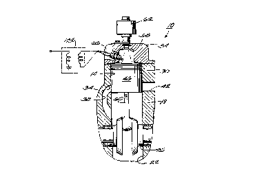
Partially shown in FIG. 1 of the Jlawillg~ is an internal combustion engine
5 10. One cylinder 14 of the engine 10 is illustrated in FIG. 1. The engine 10
in~ les a cr~nk~ce 18 defining a cr~nkc~cç chamber 22 and having a cr~nkch~ft
26 rotatable therein. An engine block 30 defines the cylinder 14. The engine
block 30 also defines an intake port 34 co.. ,.. licating between the cylinder 14
and the cr~nkc~ce chamber 22 via a transfer passage 38. The engine block 30
10 also defines an eYh~lct port 42. A piston 46 is reciprocally moveable in the
cylinder 14 and is drivingly connected to the cr~nkch~ft 26 by a connecting rod
and crank pin assembly 50. A cylinder head 54 closes the upper end of the
cylinder 14 so as to define a combustion chamber 58. The engine 10 also
in~lurlPs a fuel injector 62 mounted on the cylinder head 54 for injecting fuel into
15 the combustion chamber 58. A spark plug 66 is mounted on the cylinder head 54 and eytpn(lc into the combustion chamber 58.
The internal combustion engine 10 also incllldes (see FIG. 2) a time delay
ignition circuit 70 for generating a spark in the cylinder 14 at a predeterminedmom.ont after the injection of fuel into the combustion chamber 58 has occurred.20 As shown in FIG. 2, the time delay ignitic ~ circuit 70 in~ des a microprocessor
74 having data outputs 78, an injection indic~tor output 82, and a spark
generating output 86. As described below, the microprocessor 74 generates spark
signals at the output 86. It should be understood, however, that the spark signals
may be generated by another a~p~op,iate component such as an ECU. The
25 circuit 70 also incll~des a timer 90 having an 8-bit register of data inputs 94 for
receiving timing information from the data outputs 78 of the microprocessor 74.
The timer 90 also has a trigger input 98 connected to the injection indicator
output 82 of the microprocessor 74 to receive from the microprocessor 74 a signal
indicating when an injection event has been initi~te~l by the microprocessor 74.30 The timer 90 also in-~hldes a timing pulse output 102.
The time delay ignition circuit 70 also jncllldes an AND gate 106 having two
mputs 110 and 114 and an output 118. Input 110 of AND gate 106 is connected
to the output 102 of the timer 90. Input 114 of AND gate 106 is connected to
CA 022~810~ 1998-12-08
- WO 97/48903 PCT/US97/10636
the microprocessor 74 to receive from the microprocessor 74 a spark generating
signal from spark generating output 86. The output 118 of the AND gate 106 is
connected to an ignition coil 122 (shown schem~tic~lly in FIG. 1) to generate a
spark in the cylinder 14 and igmte the fuel in the cylinder 14.
In operation, when an injection event occurs, the timer 90 receives, from
output 82 of microprocessor 74, and injection control signal (see reference
numeral 2 in F~G. 3) at the trigger input 98 of timer 90 and, in response to theinjection control signal, begins to count the dock pulses from the microprocessor
clock signal. As long as the timer count has not expired, the timer 90 generatesat the output 102 a high signal or timing signal (see reference numeral 3 in FIG.
3). When the microprocessor 74 generates the spark signal at the output 86 (see
reference numeral 4 in FIG. 3), and this spark signal is received at the input 114
to the AND gate 106, the AND gate 106 generates at output 118 an output or
ignition signal or ~;ulrelll which is tr~ncmitte~l to the ignition coil 122 (seereference numeral 5 in FIG. 3). The output 118 goes low (see reference numeral
6 in FIG. 3) when the output 102 goes low (see reference numeral 7 in FIG. 3).
While the output 118 is high, ~llrlelll flowing through the ignition coil rises. The
output 102 goes low when the timer count received from the microprocessor has
expired, r~llcin~ the output 118 to go low, i.e., when the microprocessor 74
20 indicates that the desired amount of time has elapsed since the injection event.
Rec~lce the current in an in~ r or ignition coil cannot change i.~ "eously
(V = L(di/dt)), the abrupt change in the current supply to the ignition coil causes
the voltage on the ignition coil to quickly rise thereby generating a spark c~llsin~
ignition of the fuel in the cylinder 14. In order to accommod~te various sized
25 engin~s having various numbers of cylinders, the time delay ignition circuit 70 of
F~G. 2 can be repeated as many times as there are cylinders.
While the ignition circuit 70 may be used at any speed, the ignition circuit
70 is preferably used at low or idle speeds, i.e., speeds of 200 to 2000 cr~nkch~ft
rotations per minute (RPM), and has been shown to operate particularly well at
30 speeds as low as 200 RPM. At speeds above 2000 RPM, the engine is preferably
controlled using a conventional cr~nkch~* angle-based ignition system. In both
convt;,lLional internal combustion engines and the internal combustion engine 10shown in the drawings, timing of the spark generating signal at such speeds is
CA 022~810~ 1998-12-08
- WO 97/48903 PCT/US97/10636
based solely on the crank angle of the cr~nkch~ft. However, in the prior art, the
spark generating signal is connected directly to the ignition coil and initiates the
ignition spark directly and without the need for any additional sign~l~. The result
is that the timing of prior art ignition events is dependent upon crank angle
S rather than upon absolute time calc~ tell from a fixed point in time. In contrast,
the igrution circuit 70 causes ignition to always occur a predetermined amount of
time after the injection event occurs, and this predeterrnined amount of time isnot based on the crank angle of the cr~nkchslft. The fuel injection event is thegeneration of the fuel injection signal at output 86 of microprocessor 74. This
10 may occur either at energization of the fuel injector or upon actual injection of
the fuel into the cylinder 14.
F~G. 4 illustrates a time delay ignition circuit 200 for a six cylinder engine.
Like parts are identified using like reference numerals. Rather than repeating
the circuit 70 of FIG. 2 six times, the embodiment illustrated in FIG. 4 co,ll~hles
15 (multiplexes) various signals to achieve some economy in the use of electronic
components.
As shown in FIG. 4, the circuit 200 inl~lndes a timer 204 having an 8-bit data
input register 208, three trigger inputs 212, 216, and ~o collesponding to
cylinders one and four, two and five, and three and six, re~ectively~ a clock input
20 224 and three oul~,ul5 ~8, 232, and 236 cor~e~onding to trigger inputs 212, 216,
and 220, respectively. The circuit 200 also inrl~ldes OR gates 240, 244, and 248having outputs 252, 256, and 260, respectively, which are connected to trigger
inputs 212, 216, and 220, respectively. OR gates 240, 244, and 248 also include
inputs 264 and 268, 272 and 276, and 280 and 284, respectively, connPcte~l to the
25 microprocessor 74 to receive injection output signals indicating that an injection
event has occurred in a given cylinder. That is, the microprocessor generates
output signals at oul~uls 288, 292, 296, 300, 304, and 308 to in~lic~te that injectiQn
has occurred in cylinders one, two, five, three, and six, respectively.
The time delay i~nition circuit 200 also includes AND gates 312, 316, and
30 320 having respective pairs of inputs 324, 328, and 332 connected to timer outputs
228, 232, and 236, respectively, and having respective uullJuls 336, 340, and 344.
The time delay ignition circuit 200 also includes AND gate 348 having an input
352 connected to the output 336 of AND gate 312, an input 356 and an output
... ... .
CA 022~810~ 1998-12-08
- WO 97/48903 PCT/US97/10636
360; AND gate 364 having an input 368 connected to the output 340 of AND
gate 316, an input 372 and an output 376; AND gate 380 having an input 384
connected to the output 344 of AND gate 320, an input 388 and an output 392;
an AND gate 396 having an input 400 connected to the output 344 of AND gate
5 32Q and input 404 and an output 408. Inputs 356 and 372 of AND gates 348 and
364, respectively, are connected to the microprocessor 74 to receive the spark
signals from oul~ul~ 412 and 416, resl~e.;Lively, of microprocessor 74. In time
delay ignition circuit 200, the spark signals from the microprocessor for cylinders
one and four are multiplexed, i.e., combined, on output 412 and the spark signals
10 for cylinders two and five are multiplexed on output 416. Inputs 388 and 404 of
AND gates 380 and 396, respectively, are connected to the microprocessor 74 to
receive the spark signals from outputs 420 and 424, respectively, of
microprocessor 74. Output 420 generates the spark signal for cylinder three while
output 424 generates the spark signal for cylinder six. The oul~uts 392 and 408
15 of AND gates 380 and 396, provide the ignition control signals for ignition coils
of cylinders three and six, respectively. Alternatively, the ignition control signals
for cylinders three and six could be generated by the microprocessor 74 in
multiplexed form and combined along with the col"bined timing output signal at
344 and demultiplexed by a circuit similar to DMUX 428. The oul~uls 360 and
20 376 of AND gates 348 and 364, respectively, provide the multiplexed ignition
control signals for ignition coils of cylinders one and four and cylinders two and
five, respectively.
The time delay ignition control circuit 200 also inrl~ldes a demultiplexer
(DMUX) 428. The DMUX 428 inr.l~-le,c AND gates 432 and 436 and AND gates
25 44Q 444, 448, and 452. DMUX receives as inputs the oullJuls 360 and 376 of
AND gates 348 and 364, respectively, and control oulyuls 456 and 460 of
microprocessor 74 to demultiplex the multiplexed ignition control signals for
cylinders one and four and two and five that are generated at outputs 360 and
376, respectively. DMUX generates the demultiplexed ignition control signals at
30 oul~ 464, 468, 472, and 476 for cylinders one, four, two, and five, respectively.
In operation, the time delay ignition circuit 200 is used at low speeds, i.e.,
speeds of 200 to 2000 cr~nkch~* rotations per rninute (RPM), and has ~een
shown to operate particularly well at speeds as low as 200 RPM. At speeds
CA 022~810~ 1998-12-08
- WO 97/48903 PCT/US97/10636
_9
above 2000 RPM the ignition is preferably controlled using a conventional
cr~n~ch~ft angle-based timing system. The microprocessor supplies an injection
signal for cylinder one at input 264 of OR gate 240 and for cylinder four at input
268 of OR gate 240. Thus the injection signals for cylinders one and four are
5 combined at the output 252 of the OR gate 240. Likewise, the injection signalsfor cylinders two and five are combined at the output 256 of OR gate 244 and theinjection signals for cylinders three and six are combined at the output 260 of OR
gate 248. The injection signals are input to timer trigger inputs 212, 216, and 220,
respectively. Based on multiplexed timing data received from the microprocessor
10 via data inputs 208, a combined timing signal is generated for cylinders one and
four at output 228, for cylinders two and five at output 232, and for cylinders
three and six at output 236. The combined tirning signals are combined with
comhined spark control signals for cylinders one and four, and cylinders two andfive, respectively, to create a pair of combined ignition signals for cylinders one
15 and four, and two and five. DMUX 428 demultiplexes the combined ignition
signals to generate an absolute time-based ignition signal for cylinders one, four,
two, and five.
The microprocessor also generates separate spark control signals for
cylinders three and six at microprocessor outputs 420 and 424, respectively. The20 spark control signals are input to AND gates 380 and 396 to generate absolutetime-based ignition signals for cylinders three and six at o~l~uls 392 and 408,
respectively.
While the embo~limeIlt described above changes between time-based
ignition and crank-angle-based ignition on the basis of engine speed only, one or
25 more of a variety of other engine parameters may be used, either alone or in
combin~tion, to determine when to switch between time-based ignition and crank-
angle-based ignition Examples of other a~lopliate engine parameters incl~1~1e
engine load, throttle position or some other a~propl;ate parameter.
FIGS. 5-9 illustrate, in chart form, the injection timing, ignition timing,
30 absolute m~xi....~ ignition coil on-time, preferred ignition coil on-time andinjection pulse time of a control scheme for the ignition circuit 200. As shown in
FIGS. 5-9, the engine operates with time-based ignition at a low percelllage of
wide open throttle (al~ro~i...~tely 15% of wide open throttle or below) and with
~......... , . ~ .
CA 022~810~ 1998-12-08
- WO 97/48903 PCT/US97/10636
-~0-
crank-angle-based ignition at a high percentage of wide open throttle (above
a~roki,..~tely 15% of wide open throttle). That is, the change from time-based
ignition to crank-angle-based ignition is based solely on the throttle position
me~ red as a percentage of wide open throttle.
The injection timing shown in FIG. 5 is measured in degrees before top-
dead-center. When the ignition circuit 200 is operating in the time-based mode,
i.e., the throttle position is 150 or less, the injection timing numbers in FIG. 5
represent the number of degrees before top-dead-center that the c~nlellt begins
to flow in the fuel injector coil. When the ignition circuit 200 is operating in the
crank-angle-based mode, i.e., the throttle position is greater than 150, the
injection timing numbers in FIG. 5 represent the number of degrees before top-
dead-center that fuel spray into the combustion chamber begins.
FIG. 10 illustrates graphically the change between time-based ignition and
crank-angle-based ignition for another ~lternative control scheme for the ignitiOn
circuit 200. As shown in FIG. 10, the engine operates with time-based ignition at
a low percentage of throttle position and at low speed, and operates with crank-angle-based ignition at either a high percentage of throttle position or at highspeeds. As shown in F~G. 10, ignition is time based if engine speed is below 1000
RPM and operator throttle demand is less than twenty percent (i.e., the throttle20 position sensor detects a throttle position less than twenty percent of .~.~xi...v... -
shown as "200 T.P.S." in FIG. 10). If engine speed is above 1000 RPM or
operator throttle dem~n~l is greater than twenty percent, ignition iS crank-angle-
based. This is controlled by the ECU, as described above. It has been found
that this "dual strategy" of transition from time-based ignitiQn to crank-angle-
25 based ignition provides good running quality in an outboard motor by crossingover by engine speed and provides good acceleration characteristics by crossing
over by throttle position. The preferred ignition system is fli~ losed in U.S. Serial
No. 60/02Q033, filed June 21, 1996, and titled "MULTIPLE SPARK
CAPACmVE DISCHARGE IGNmON SYSTEM FOR AN INTERNAL
30 COMBUSTION ENGINE", which is incorporated hereby by reference.
Various features and advantages are set forth in the following claims.
The co"es~onding structures, materials, acts, and equivalents of all means
or step plus function elements in the claims below are intended to include any
CA 02258105 1998-12-08
- WO 97/48903 PCT/US97/10636
structure, material, or act for pe.rol-l~ng the function in combination with other
claimed elements as specifically rl~im~