Note : Les descriptions sont présentées dans la langue officielle dans laquelle elles ont été soumises.
CA 02258583 1998-12-16
WO 97/49635 PCT/AU97/00398
- 1 -
SAFETY STIRRUP
This invention relates to horse riding stirrups
and is particularly concerned with safety stirrups which
prevent the riders foot from being caught in the stirrup
in the event of the inadvertent dismounting of the rider
such as being thrown from the horse.
Known types of stirrups generally include a D-
shaped metal structure with a slot located in the centre of
the arcuate portion of the D to enable the stirrup to be
attached to a stirrup strap. In use, the rider's foot is
inserted into the stirrup such that a base portion defined
by an inner surface of the upright of the D of the stirrup
locates against the sole of the rider s foot and the
arcuate portion of the stirrup locates against the top of
the rider's foot. In this way the rider's foot is held in
place and is not easily dislodged from the stirrup when the
gait of the horse increases.
A disadvantage of existing stirrups is that in
the event of the rider falling from the saddle, one of the
rider's feet can become caught in the stirrup. This a.s
particularly the case when a rider is thrown from the
horse, the swiftness of which does not allow the rider to
extract a foot caught in a stirrup. Catching of a foot in
a stirrup can cause serious injury to the rider since the
rider may be dragged along beside the horse.
Safety stirrups have previously been devised to
overcome some of these problems. One form of safety
stirrup includes a frangible or weakened portion of the
stirrup located adjacent to the stirrup strap attachment
slot. In use, this frangible portion is designed to break
away if the rider's foot is caught in the stirrup when the
rider is thrown from the saddle.
CA 02258583 1998-12-16
WO 97/49635 PCT/AU97/00398
- 2 -
This frangible stirrup is satisfactory in that
the rider is saved from further injury which may be caused
by being dragged along the ground. However. the rider
cannot easily remount, since the saddle now has only one
operable stirrup and the rider may be thrown from the
saddle again should the horse increase its gait. Hence the
rider should replace the broken frangible stirrup before
continuing, which may be inconvenient or impossible.
Also, the frangible stirrup often does not
prevent the rider from suffering leg injuries. Hence, they
are only of limited benefit for novice or disabled riders.
A further disadvantage of these stirrups is that they are
more bulky than conventional stirrups in the region of
attachment to the stirrup strap and this increased bulk
often causes wear to the rider's clothing.
An alternative form of safety stirrups is
disclosed in Australian Patent Application No. 62109/90.
Tn this stirrup, the foot is held in a restraint which is
pivotally mounted on an inverted U-shaped mounting means.
The restraint is pivoted out of the normal position and
separates if the rider is thrown from the horse, the
separation of the restraint releases the foot from the
restraint. A disadvantage of this type of stirrup is that
the foot may still be retained within the U-shaped mounting
means even when the restraint is pivoted out of the normal
position and separates.
Another form of safety stirrup is disclosed in
=nternational patent Application No. PCT/AU95/00332. In
this stirrup the foot is held in a restraint means which is
pivotally mounted between two extremities of an inverted U-
shaped mounting means. =f the rider is thrown from the
horse, the restraint means pivots out of the normal
position, one of the pivotal mountings releases from the
mounting member and the restraint means separates, thus
CA 02258583 1998-12-16
WO 97/49635 PCT/AU97/00398
- 3 -
releasing the foot from both the restraint and the inverted
U-shaped mounting means. One of the disadvantages of the
type of stirrup is that the restraint means can be pushed
out of the normal position by the movement and pressure
exerted on the stirrup by hard riding. For example,
professional riders such as jockeys, mountain cattlemen,
rodeo riders and the like exert enormous pressure on
stirrups as they pull up a horse or lean back to resist
being thrown over the horse's head. The strong pressure of
the rider forcing a foot hard into the stirrup can cause
stirrups of the prior art to suddenly release the foot,
unbalancing the rider and potentially causing the rider to
fall from the horse.
It is an object of the present invention to
provide a stirrup which alleviates or overcomes the
disadvantages of existing stirrups. It is a further object
of the present invention to provide a stirrup which
alleviates the problem of unexpected or undesirable release
of stirrups during hard riding or manoeuvring of a horse.
According to the present invention there is
provided a safety stirrup comprising:
- an inverted U-shaped mounting member having means
located in the arcuate portion of the U to enable a stirrup
strap to be attached thereto:
- a foot support pivotally mounted between the
extremities of the mounting member when the stirrup is in
normal use, wherein the foot support comprises a tread
having an extension projecting upwardly from each end of
the tread, and a foot upper restraining portion comprising
two arms which co-operate together to form a looped
configuration extending from the extensions formed on the
tread, each said arm being pivotal outwardly from its
adjacent support extension: arid
CA 02258583 1998-12-16
WO 97/49635 PCT/AU97/00398
- 4 -
- restriction means acting between the foot upper
restraining portion and the inverted U-shaped mounting
member to restrict the movement of the foot upper
restraining portion to the direction which is oppasite to
the direction in which the foot is inserted:
wherein said foot support is releasable from said
pivotal mounting at one extremity of said mounting member
after pivoting of said foot support from the normal in use
arrangement and the other extremity of said mounting member
is pivotal outwardly, and wherein said pivoting of the foot
support from the normal in use arrangement enables the arms
of the foot upper restraining portion to pivot outwardly
and/or said foot support to release from said one extremity
of said mounting member. In general, the foot upper
restraining portion will remain in a plane within the U-
shaped mounting member due to interference fit. However,
the foot support may optionally include a co-operating
engagement means between the foot upper restraining portion
and the inverted U-shaped mounting member to retain the
foot upper restraining portion in a plane within the
inverted U-shaped mounting member when the stirrup is in
said normal use and to thereby prevent the arms of the foot
upper restraining portion from pivoting outwards.
The term "normal use" is used in the preceding
paragraph and hereafter to denote the configuration of the
stirrup when a rider a.s mounted on a horse to which the
stirrup is fitted with the rider's foot positioned in the
stirrup.
The pivotal mounting of the foot support to the
mounting member may be achieved by any convenient means, '
but is typically by way of shafts or pins. Preferably, the
pins or shafts extend from, or are received by, the
extensions projecting from the tread_
CA 02258583 1998-12-16
WO 97/49635 PCT/AU97/00398
- 5 -
In the case of the pivotal mounting of the foot
support which a.s releasable from one extremity of the
mounting member, the pivot typically comprises a pin
projecting from the foot support which is received by an
aperture in the mounting member. To effect release from
the mounting member, the pin can be provided with flattened
portions which on rotation of the foot support, allow the
pin to pass through a slot in the mounting member between
the aperture and the edge of the mounting member. To aid
release of the pin, the walls of the slot preferably flare
outwardly away from the aperture. The angle between the
slot walls is typically about 45°.
In a preferred embodiment, the pin described in
the preceding paragraph has a head which prevents excessive
spreading of the extremities of the mounting member when
the pin is located in the aperture in the mounting member.
Advantageously, the head stands slightly away from the
adjacent surface of the mounting member to provide a gap
therebetween when the pin is located in the aperture.
Depending on the nature of the co-operating engagement
means between the foot upper restraining portion and the
mounting member, the aforementioned gap can facilitate
disengagement of the foot upper restraining portion and the
mounting member by allowing spreading of the extremities of
the mounting member.
In preferred embodiments where the pivotal
mounting of the foot support to an extremity of the
mounting member includes a pin having a head, a recess is
typically provided in the mounting member around the
aperture therein, which recess can receive the head of the
a pin when the pin is located in the aperture. The bulk of
the head advantageously lies within the recess resulting a.n
the mounting member having a substantially smooth outer
surface .
CA 02258583 1998-12-16
WO 97!49635 PCTlAU9710~398
- 6 -
In the ease of the pivotal mounting of the foot
support to the other extremity of the mounting member, the
mounting preferably comprises a screw which passes from the
exterior of the stirrup through the U-shaped mounting
member to be threadingly engaged by the foot support. The
screw is typically contained within a dual diameter cavity
in the mounting member with the screw having an enlarged'
head which recesses into the wider diameter cavity. The
screw threaded portion of the screw is suitably formed on a
narrower diameter section at the end of the screw.
The foot upper restraining portion is preferably
arcuate in shape and the arms preferably cooperate in a
male/female arrangement. This typically comprises an
integrally formed pin extending from the tip of one of the
arms of the foot upper restraining portion which is
accommodated in a complementary shaped recess formed in the
tip of the other of said arms.
The co-operating engagement means is preferably a
projection formed on each arm of the foot upper restraining
portion, adjacent to the pivotal connection with the
support extension, and an aligned socket formed in the
inwardly facing arms of the inverted U-shaped mounting
member. The projection is suitably maintained within the
socket to thereby prevent pivotal rotation of the foot
upper restraining means from the plane of the mounting
member during normal use, by spring-biasing the sides of
the mounting member against the restraining means. The
projections could egually well be formed on the inwardly
facing sides of the mounting member with corresponding
sockets formed a.n the foot upper restraining portion.
The pivot between a restraining portion arm and
adjacent projecting extension, and the other extremity of
the mounting member and the remainder of the mounting
CA 02258583 1998-12-16
WO 97/49635 PCT/AU97/00398
_ 7 _
member, typically comprises interdigitating elements
through which a pin is passed. The interdigitated elements
help to maintain the integrity of the stirrup when in the
normal in use arrangement.
The restriction means may comprise one or more,
preferably two, projections which extend from the U-shaped
mounting member or one or more arms of the foot upper
restraining portion. Where the restriction means projects
from the side of the U-shaped mounting member, it may
engage against the foot upper restraining' portion when the
stirrup is in normal use. The restriction means will
suitably overlap the foot upper restraining portion to
thereby prevent pivoting of the restraining portion through
the plane of the mounting member. That is, pivoting can
only occur in one direction. A similar result may be
achieved by one or more, preferably two, restriction means
comprising projections extending from the foot upper
restraining portion which projections engage the mounting
member.
During use of the stirrup a foot must be placed
in the stirrup from a particular side for the release
mechanism to operate. In general those riders who ride
sufficiently hard to require a stirrup which releases only
in one particular direction, will be professional or expert
riders who are sufficiently knowledgeable and experienced
to place their stirrups in the correct orientation for the
release mechanism to operate if they are thrown from the
horse.
The means for locating the stirrup strap in the
mounting member can be a conventional arrangement such as a
slot through which the strap is threaded a bar around which
the strap wraps, or a known toggle-type connection. The
slot on bar arrangements are preferred.
CA 02258583 2006-05-29
8
Suitably, the tread of the foot support is in the
form of a case plate or slotted plate which is oriented in
a generally horizontal plane in use. Preferably the
extensions formed on the tread are walls which are
integrally formed with the ends of the tread.
The invention will now be further described with
reference to the following drawings in which,
Figure 1 is an elevational view in partial
section of a safety stirrup in its normal in use
configuration and constructed in accordance With the
present invention.
Figure 2 is a perspective view of the stirrup of
Figure 1 depicting a foot releasing configuration.
Figure 3 is an elevational view in partial
section of another safety stirrup according to the
invention in normal in use configuration.
Figure 4 is a perspective view showing detail of
a portion of the stirrup depicted in Figure 3.
Figures 5a through 5c are a perspective view
and two side views of another safety stirrup according to
the present invention in normal use configuration.
Figures 6, 7 and 8 are perspective views of three
other safety stirrups according to the present invention in
normal use configuration.
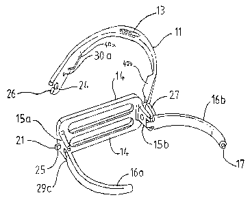
Referring to Figures 1 and 2 in which like
numbered parts indicate the same features, the safety
stirrup 10 comprises an inverted U-shaped mounting member
11 with a foot support 12 provided between the extremities
thereof. A slot 13 is located in the arcuate portion of
CA 02258583 1998-12-16
WO 97/49635 PCT/AU97/00398
_ g _
mounting member Z1 for attachment of a stirrup strap (not
illustrated) in a known. manner.
Foot support 12 consists of a tread 14 having
projecting extensions 15a and 15b, and arms 16a and 16b
together constituting the foot upper restraining portion of
the foot support. Arms 16a and 16b can interlock by virtue
of pin 17 at the end of one arm which is received by a
recess 18 a.n the end of the other arm (not shown in Figure
2). Arms 16a and 16b are pivotally connected to projecting
extensions 15a and 15b via roll pins 19a and 19b.
The foot support 12 can pivot between the
extremities of mounting member 11 by means of screw 20 and
pin 21. Screw 20 has an enlarged collar portion 22 which
can rotate in an aperture in mounting member 11. The
threaded portion 23 of the screw retains the screw in
projecting extension 15b of the foot support. The mounting
member extremity a.s retained by head 20a of screw 20. A
gap a.s provided between the underside of head 20a and the
adjacent surface of mounting member 11. to allow slight
outward movement of the extremity of the member during
pivoting of foot support 12 out of the normal in use
p081.t1.On.
On the other side of the foot support, pin 21,
which extends from projecting extension 15a, is located a.n
aperture 24 when the stirrup is in normal use. Pin 21 has
flattened sides, one of which is shown at 25 of Figure 2.
The mounting member extremity having aperture 24 also has a
slot extending between the aperture and the edge of the
mounting member. The slot can be seen more clearly in
Figure 2 and an angled face of the slot is indicated at 26.
The mounting member extremity opposite the
extremity having aperture 24 is pivotable with respect to
the rest of the mounting member. The pivotable portion 27
CA 02258583 1998-12-16
WO 97/49635 PCT/AU97/00398
- 10 -
of mounting member 11 is connected to the mounting member
via pin 28.
The flattened portions of pin 21 in conjunction
with pivotal portion 27 of mounting member 11, allow the
pin to be released from aperture 24 when the pin is
sufficiently rotated to align the flattened portions with
the slot in the mounting member extremity.
Co-operative engagement means are provided
between arms 16a and 16b of foot support 12 and the
mounting member 11 to retain the foot support in a plane
within the mounting member when the stirrup is in normal
use. Such means comprises dimple projections 29a and 29b
on each of the arms and sockets 30a and 30b formed in the
mounting member. In normal use, the dimple projections 29a
and 29b are retained within the sockets 30a and 30b by
virtue of the mounting member being spring biased against
the arms 16a arid 16b of the foot support 12.
Restriction means 40a and 40b project inwardly
from the sides of the U-shaped mounting member. Each
restriction means overlaps part of the toot upper
restraining portion of the foot support to prevent pivoting
of the restraining portion through the plane of the
mounting member.
=n normal use, that is, with the stirrup arranged
as depicted in Figure l, the riders foot is inserted
through the stirrup (that is, the opposite side to that
depicted in Figures 1 and 4) to a position where the sole
of the foot rests on the tread 14 and the foot upper -
contacts the loop, the foot upper restraining portion of
the foot support formed by the arms 16a and 16b. Pivoting .
of the foot support 12 is prevented during normal riding
due to the downward pressure of the foot on the foot
support and the spring biasing of the mounting member
CA 02258583 1998-12-16
WO 97/49635 PCf/AU97/00398
_ 11 _
against the arms of the foot support which ensures that the
co-operative engagement means, viz the dimple projections
29a and 29b and sockets 30a and 30b, are maintained in
close abutment.
During heavy riding or manoeuvring of the horse
the downward and forward pressure exerted on the foot
support would be sufficient to overcome the force of the
spring biasing of the mounting member against the arms of
the foot support, however the restriction means suitably
overlap the foot upper restraining portion to thereby
prevent pivoting of the restraining portion through the
plane of the mounting member. That is restraining portion
cannot pivot in the direction of the toe of the foot.
15-
When the rider is thrown from the saddle,
reorientation of the rider's toot from a substantially
horizontal riding position to a downwardly inclined
position causes a turning force to be exerted by the
rider's foot against the foot support 12. This turning
force a.s sufficient to overcome the spring biasing force
retaining the dimple projections 29a and 29b in the soc3sets
30a, and 30b and the entire foot upper restraining means
pivots out of the plane of the mounting member l1 towards
the heel of the foot to a position such as indicated in
Figure 2. Simultaneous with such pivoting, once the foot
support arms have passed the sides of the mounting member
11, the force imposed by the foot causes the arms 16a, 16b
to immediately pivot outwardly from each other about their
pivot points and/or the foot support to be released from
the mounting member extremity having aperture 24 with
pivoting of portion 27. Conseguently, the rider's foot is
released from the stirrup.
- Tn this manner, the rider's foot is prevented
from being caught in the stirrup after inadvertent
dismounting, thus reducing the possibility of injury to the
CA 02258583 1998-12-16
WO 97/49635 PCT/AU97/00398
- 12 -
rider. Furthermore, the stirrup is such that it can
readily be returned to its normal in use position by simply
pivoting the two arms 16a, 16b together, repositioning pin
21 in aperture 24, and rotating the foot support back to
the plane of the mounting member by mere hand manipulation.
This is possible since the spring biasing force exerted by
the mounting' portion can readily be overcome by simple hand
exertion.
This is particularly important to enable the
rider to immediately remount after being thrown from the
saddle.
Referring now to Figure 3, there is shown safety
stirrup 50 having U-shaped mounting member 51 comprising
restriction means 40a and 40b, and foot support 52. With
the exception of the pivot pin at the bottom left of the
stirrup depicted j.n the figure, all other features of the
stirrup are essentially the same as the stirrup depicted in
Figures 1 and 2.
Pin 53 extends from projecting extension 54 of
tread 55 of foot support 52 of Figure 3 like pin 21 of
Figures 1 and 2. However, pin 53 has a head 56 which can
be received by a recess 57 in the outward face of the
extremity of mounting member 51. It can be appreciated
from Figure 3 that a gap is allowed between the underside
of head 56 and the bottom of recess 57 to permit some
outward movement of the extremity of mounting member 51
when foot support 52 disengages therefrom.
Detail of how pin 53 can be retained by mounting -
member 51 and pivotally released therefrom is provided in
Figure 4 where like items are identically numbered with
respect to Figure 3. Portions of mounting member 51 and
foot support 52 can be seen, the latter including portion
of tread 55. Pin 53, which can be seen projecting from
CA 02258583 1998-12-16
WO 97/49635 PCT/AU97/00398
- 13 -
projecting extension 54, has flattened, sides one of which
indicated at 58. Recess 57 can be seen in the extremity of
mounting member 51 shown a.n Figure 4 plus aperture 59.
Aperture 59 has a slot therein through which pin 53 can
pass when sufficiently rotated to align the flattened sides
with the slot. As in the Figures 1 and 2 stirrup, faces 60
and 61 of the slot flare outwardly away from aperture 59 to
facilitate disengagement of pin 53 from aperture 59 or
fitting of the pin into the aperture.
It can be appreciated that recess 57 is open on
the side corresponding to the slot in aperture 59 to permit
release of head 56 from the recess.
=t can be also appreciated from Figures 2 and 4
that tread 14 of the stirrup shown in the former figure
includes three cross-pieces whereas tread 55 of the Figure
4 stirrup includes two cross-pieces.
Referring to Figure 5(a) the safety stirrup
comprises an inverted U-shaped mounting member 62 with a
foot support 64 between the extremities thereof. A slot 65
a.s located in the arcuate portion of the mounting member 62
for attachment of a stirrup strap. The foot support
comprises projecting extensions 66a(and 66b, riot shown),
and arms 68a and 68b which interloclt by virtue of a pin
(not shown) at the end of one arm which is received in the
end of the other arm. The ends of the arms are pressed
together by virtue of the tight fit of the two arms between
the projecting extensions and within the plane of the U-
shaped mounting member. The arms 68a and 68b are pivotally
connected to projecting extensions 66a and 66b by pins 69a
and 69b.
An L-shaped restriction means 70 projects
outwards from one arm 68b and fits at least partially into
a recess 71 on the outer side of the extremity of the U-
CA 02258583 1998-12-16
WO 97/49635 PCT/AU97/00398
- 14 _
shaped mounting member.
Figure 5(b) is a view along AA' showing one side
of the stirrup including an extremity of the mounting
member 62, retained by pin 69b. Figure 5(c) is a view
along A'A showing the other side of the stirrup including
the other extremity of the mounting member 62 and its
pivotal attachment to an extremity of the foot support.
Figure 6 shows a jockey stirrup according to the
present invention. The stirrup is attached to the mounting
member by a saddle strap passed through the opening 84.
The foot support 72 consists of a tread 74 which curves
upwards to provide two projecting extensions 75a and 75b
and arms 76a and 76b which interlock at point 77. Arms 76a
and 76b are pivotally connected to the projecting
extensions °75a and 75b. The foot support 72 is pivotally
connected by a pin 79 to one extremity of the mounting
member 80. The other extremity of the mounting member
comprises a recess which is adapted to receive a pin 82
(riot shown) which terminates in an enlarged head 82'. In
normal use, two restraining means 84a and 84b on the
mounting member are located in recesses in each of the two
arms 76a and 76b. In use, a jockey inserts his foot into
the stirrup in the direction 8'B, exerting force against
the foot upper restraining means and during hard riding,
pressing the arms 76a and 76b against the restraining means
84a and 84b. Should the jockey be dismounted during
riding, with a foot remaining trapped in the stirrup, the
toot upper restraining means will pivot in the direction B'
(towards the ankle of the trapped foot) about pin 79 and
82. The foot upper restraining means disconnecting from
the extremity of the mounting member at pin 82 and the two
arms 76a and 76b will disconnect at 77, opening to release -
the jockey's foot.
Figure 7 depicts a safety stirrup which operates
CA 02258583 1998-12-16
WO 97!49635 PCT/AU97/00398
- 15 -
in the same manner as the jockey stirrup depicted in Figure
6. The stirrup is larger and heavier in construction than
the jockey stirrup and is used fox applications other than
flat racing such as rounding cattle and other farm related
work. The mounting member 86 is still generally U-shaped,
but unlike the jockey stirrup, the saddle strap which
attaches the stirrup to the saddle, passes around the bar-
shaped top 87 of the mounting member rather than through a
recess in the mounting member. However, variations on the
conformation of the mounting member having such a recess
for the saddle strap could be used.
Figure 8 depicts a safety stirrup of a type which
is similar to the stirrup of Figure 7 but of different
design. Notably the safety stirrup of Figure 7 has a
flatter, broader tread 89 than the safety stirrup of Figure
6.
While the foregoing describes preferred
embodiments of the invention, various modifications can be
included without departing from the spirit of the
invention.