Note : Les descriptions sont présentées dans la langue officielle dans laquelle elles ont été soumises.
CA 02259049 1999-03-O1
WINDROW GROUPER ARRANGEMENT
Background of the Invention
The invention concerns a windrow grouper arrangement for use together with a
mowing implement that normally forms a single windrow of crop, the grouper
including a
conveyor arrangement which transports crap to be windrowed to one side and
which can be
brought into an operating position that accepts crop and a non-operating
position that does
not accept crop exiting from the windrow forming discharge housing of the
mower.
EP-A1-0 439 991 discloses a windrow grouper arrangement that is attached to a
mowing implement and takes up crop harvested by the implement and deposits it
to the side
or that can be brought into a non-operating position, in which the mowed crop
falls to the
ground. The grouper arrangement includes a conveyor arrangement consisting of
several
rolls arranged parallel to each other, which rotate in the same direction and
thereby convey
the mowed crop to the side. The rotational speed of the rolls can be varied in
order to
change the distance of ejection.
EP-A1-0 165 602 reveals a windrow grouper arrangement including a conveyor
belt
as a conveying device. When necessary, this grouper can be attached to the
mowing
implement and is then connected to it in a fixed position. The conveyor belt
can be shifted
to the side within the conveying device in order to deliver the crop at
various distances or at
a different side.
According to EP-A1-0 779 020, a windrow grouper arrangement includes a
conveyor
arrangement supported on a mowing implement by means of parallel arms so that
it can be
moved to the side, and hence can occupy various sideways positions with
respect to the
mowing implement, so that the windrow to be generated can be deposited at
various
transverse locations relative to the mowing implement. In order to assure that
the crop is
not scattered when it reaches the ground, a shield is provided against which
the crop is
thrown so that a more or less exact side edge of the swath results.
The problem underlying the invention is seen in the fact that the known
arrangements for depositing crop windrows alongside each other are capable
only of
forming a double windrow and crop processing machines such as forage
harvesters have
the capacity to process more crop than is deposited in two windrows.
Summary of the Invention
According to the present invention, there is provided an improved windrow
grouping
arrangement.
A broad object of the invention is to provide a windrow grouping arrangement
capable of depositing three swaths or windrows together.
CA 02259049 1999-03-O1
A more specific object of the invention is to provide in combination with a
mower
having the capability of forming one windrow, a grouper attachment having
modes of
operation capable of placing two other windrows in side-by-side relationship
to the one
formed by the mower, thereby leaving a total of three windrows for subsequent
processing
by another crop processing implement such as a forage harvester. This object
is
accomplished by providing a grouper attachment in the form of a conveyor
mounted to a
transverse beam of the main frame of the mower by a combined slide and support
structure
which permits the conveyor to be shifted sideways along the frame as well as
moved
between a lowered operative position, wherein it intercepts crop discharged
from the
windrow forming housing at the rear of the mower, and a raised position
permitting the crop
exiting the mower to be formed into a windrow directly behind the mower.
These and other objects of the invention will become apparent from a reading
of the
ensuing description together with the appended drawings.
Brief Description of the Drawings
FIG. 1 shows a plan view of a harvesting machine together with a windrow
grouper
attachment constructed in accordance with the present invention.
FIG. 2 shows a vertical section taken along line 2--2 of FIG. 1.
FIG. 3 shows three operating conditions that can be attained with mower and
grouper attachment combination during field operation so as to result in the
formation of
three side-by-side windrows.
Description of the Preferred Embodiment
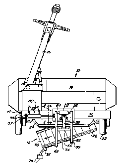
A harvesting machine 10 shown in FIG. 1 is configured as a mower and carries
at its
rear end a windrow grouper attachment 12 constructed according to the present
invention.
The harvesting machine 10 includes a frame 14, a draft tongue 16 and a
harvesting
unit or header 18, that are combined into a towed unit. The frame 14 includes
a beam 20,
that extends transverse to the direction of travel of the harvesting machine
10 and is
positioned above a rear portion of the header 18. Depending from opposite ends
of the
beam 20 are wheel support legs respectively to which ground wheels 22 are
connected.
The draft tongue 16 extends generally in the direction of travel, has its rear
end coupled to
the frame 14 for pivoting horizontally about an upright axis, and can be
coupled at its
forward end to an agricultural tractor 78 (FIG. 3).
The harvesting unit or header 18 includes a cutter bar, not shown, or another
type of
2
CA 02259049 1999-03-O1
mowing device and may also contain, if desired, a crushing or conditioning
unit, also not
shown, located between the mowing device and the grouper attachment 12. At the
rear end
region of the header 18 that extends under the beam 20, a discharge housing 24
is
provided, whose discharge opening is considerably narrower than the cutting
width of the
mowing device. In the non-operating condition of the grouper attachment 12,
the width of
the discharge opening corresponds essentially to the width of the windrow that
is formed.
Thus, the header 18 is able to sever crop over a great width from the ground
and to deposit
it in a narrow windrow on the ground.
In the embodiment shown, the windrow grouper attachment 12 includes a slide
26, a
first servomotor or hydraulic actuator 28, a support arrangement 30, a second
servomotor or
hydraulic actuator 32 and a conveyor arrangement 34 having a drive motor 36,
which is
preferably a hydraulic motor.
Referring now also to FIG. 2, it can be seen that the slide 26 is configured
in the form
of an inverted "U" and engages with its interior the beam 20 over a large
portion of its cross
section. On inner sides of opposite vertical legs 38 of the slide 26 is
provided horizontal
axles that support front and rear rollers 40 and 42, respectively. The front
roller 40 is
supported on an undersurface of a horizontal rail 44 provided at the upper
front comer of the
beam 20 and extending close to the adjacent leg 38 of the slide 26. Slide
rails or the like
including low friction slideway coatings, that are not shown, may be provided
between the
end surface of the rail 44 and the inner surface of the leg 38, for the
purpose of reducing
friction forces in the case of a possible contact between the surfaces.
The rear roller 42 is supported on an upper surface of a rail 46, that is
joined to, and
extends horizontally at approximately mid-height from, a rear side of the beam
20. This rail
46 has its outer edge located nearly to an inner surface of the rear leg 38 of
the slide 26.
Again, slide rails with low friction slideway coatings, not shown, may be
provided between
the end surface of the rail 46 and the rear leg 38 of the slide 26 so as to
reduce friction
forces in the case of possible contact. Points of contact respectively above
and below the
rollers 40 and 42 on the rails 44 and 46 is effected by the attachment and
configuration of
the support arrangement 30, which has the effect of tipping the slide 26 about
the
longitudinal axis of the beam 20 in the clockwise direction, as seen in FIG.
2. Other
methods of support of the slide 26 on the beam 20 are possible, for example,
with the use of
slideway rails, ball bearings or the like. However, in any method of support,
it is necessary
3
CA 02259049 1999-03-O1
to observe that the length of the bearing surface is so dimensioned in
proportion to the width
of the beam 20 that tilting cannot occur. The rails 44 and 46 may be
configured as a one-
piece unit with the beam 20 or they be subsequently attached to the latter,
for example, by
bolting or welding. During operation, the inner surfaces of the legs 38 and
top of the slide 26
are spaced from the ribs 44 and 46 and the top of the beam 20, however,
frictional contact
between the adjacent surfaces of the slide with the beam and ribs may occur
when the
machine 10 is traversing irregularities on the ground.
Two vertical lugs 48 are attached to, and located at approximately at half the
width of
a top surface of, the slide 26. The lugs 48 are spaced from each other in the
direction of
travel and a pin 50 extends horizontally through the lugs 48 and serves to
couple the rod
end of the hydraulic actuator 28 to the slide 26. Fixed to an upper surface
location of the
slide 26 that is above the front roller 40 is a bearing 52, the purpose of
which is explained
below. Above the rear roller 42, two vertical lugs 54 are provided that are
spaced
transversely from each other and through which a pin 56 extends and couples
the rod end of
the hydraulic actuator 32 to the slide 26.
The first servomotor or hydraulic actuator 28 is configured as a double-acting
hydraulic cylinder which, as stated above, has its rod end retained to the
slide 26 by the pin
50 and has its cylinder end coupled by a pin 57 received in a pair of fore-and-
aft spaced
lugs 58 fixed to a top, left location on the beam 20. For its actuation, the
servomotor 28 is
connected through hydraulic lines 60 with a control or regulating arrangement,
not shown,
preferably located on the towing vehicle. As can be seen, in particular in
FIG. 1, the slide
26 and with it the conveyor arrangement 34 can be moved by the first
servomotor 28 along
the beam 20.
The support arrangement 30 includes a pair of transversely spaced, parallel
arms 62
having their forvvard ends coupled by a shaft 64 and being fixed together at a
location
intermediate their front and rear ends by a cross member 66. The shaft 64 is
journalled in
the bearing 52, thereby establishing a horizontal, transverse axis about which
the support
arrangement 30 may pivot. The arms extend rearwardly beyond and then
downwardly at a
back side of the conveyor arrangement 34 where they are fixed, it being noted
that the arms
62 differ in their lengths and hence engage the conveyor arrangement 34 in
such a way that
the arrangement 34 is angled from front to rear to the direction of travel
towards the left-
hand side of the machine 10, this side being that to which the draft tongue 16
is attached.
4
CA 02259049 2001-02-14
The conveyor arrangement 34 thus ends on the opposite side of the machine 10
from the
tongue 16 alongside the left-hand wheel 22. The second servomotor 32 is
provided for
swinging the support arrangement 30 vertically and for that purpose has its
cylinder end
pivotally attached to the cross member 66, it already being noted that its rod
end is coupled
to the slide 26. By means of the servomotor 32, the support arrangement 30 can
be
pivoted vertically and thereby the conveyor arrangement 34 can be pivoted from
an
operatinct position (see FIGS. 1 and 2) underneath the discharge housing 24 to
a non-
operating position above or to the rear of the discharge housing 24, this
latter mode of
operation being depicted at the top of FIG. 3. Like the servomotor 28, the
supply of fluid to
and drainage of fluid from the servomotor 32 can be controlled by a control or
regulating
arrangement located on the towing vehicle and coupled to the actuator 32 by
hydraulic lines
68. Depending on the pivot angle selected, a single-acting hydraulic actuator
may be used
instead of the double-acting actuator 32.
The conveyor arrangement 34 as disclosed herein includes a conveyor belt 70
that is
provided with conveyor ribs extending transverse to the direction of
circulation of the belt
indicatecl by the arrow in FIG. 1. The conveyor belt 70 is supported from a
frame 72 by rolls
(not shown) mounted in bearings so that the belt 70 can circulate by means of
the rolls, and
is therefore able to convey crop accepted from the discharge housing to the
left, as seen in
FIG. 1. 'The drive motor 36 for the conveyor belt 70 is applied to one of the
rolls and is here
shown as a hydraulic motor, that is supplied through hydraulic lines 74 which
are again
supplied by the control or regulating arrangement located on the towing
vehicle. At least
one of the hydraulic lines 74 may be provided with a flow modification device
76, for
example, in the form of a valve, an orifice, a throttling restriction or the
like, by means of
which the rotational speed of the motor 36 can be varied.
C)n the basis of the description up to this point and as seen in FIG. 3, the
operation
of the grouper attachment 12 according to the invention in combination with
the harvesting
machine 10 shall be explained in the following.
FIG. 3 shows the harvesting machine 10 with the grouper attachment 12 towed by
a
towing vehicle 78 in three different operating modes which are described in
sequence from
top to bottom.
In the situation pictured at the top, the conveyor arrangement 34 of the
grouper
attachment 12 is raised so that the crop that has been mowed exits the
discharge housing
5
CA 02259049 2001-02-14
24 and falls to the ground between the wheels 22 of the harvesting machine 10
and remains
deposited there in a first windrow I.
In the operating mode depicted below this, the conveyor arrangement 34 is
lowered and intercepts crop coming from the discharge housing 24 in order to
deposit it in a
second windrow II essentially behind the left wheel 22. During this process,
the towing
vehicle 78 travels in such a way that its wheels straddle the windrow I. The
windrows I and
II are thus deposited to lie immediately alongside each other.
In the operating mode shown at the bottom of the view, the towing vehicle 78
travels
across the field that has been mowed and does not straddle windrow II. The
conveyor
arrangement 34 of the grouper attachment 12 remains in its lower position, but
is shifted to
the left by effecting contraction of the actuator 28 from its extended
position shown in FIG.
1. In this way, a windrow III is formed, not behind the left wheel 22, but to
the left of it. It
can be seen that this third windrow III lies close alongside the windrow II.
In addition to
shifting thE: conveyor arrangement 34 to the left, it is possible to operate
the drive motor 36
at a higher speed, so that the crop is deposited sufficiently far to the left
of the harvesting
machine 10. Preferably, the windrows I - I I I are together narrower than 4
meters and can
be taken up by a single pick-up of a machine, for example a forage harvester,
for further
processinca of the crop.
25
6