Sélection de la langue

Search

Sommaire du brevet 2259193 

Énoncé de désistement de responsabilité concernant l'information provenant de tiers

Une partie des informations de ce site Web a été fournie par des sources externes. Le gouvernement du Canada n'assume aucune responsabilité concernant la précision, l'actualité ou la fiabilité des informations fournies par les sources externes. Les utilisateurs qui désirent employer cette information devraient consulter directement la source des informations. Le contenu fourni par les sources externes n'est pas assujetti aux exigences sur les langues officielles, la protection des renseignements personnels et l'accessibilité.

Disponibilité de l'Abrégé et des Revendications

L'apparition de différences dans le texte et l'image des Revendications et de l'Abrégé dépend du moment auquel le document est publié. Les textes des Revendications et de l'Abrégé sont affichés :

  • lorsque la demande peut être examinée par le public;
  • lorsque le brevet est émis (délivrance).
(12) Brevet: (11) CA 2259193
(54) Titre français: MECANISME DE PROPULSION DE NAVIRE EN FUSEAU AVEC MOTEUR SYNCHRONE
(54) Titre anglais: POD-LIKE SHIP PROPULSION SYSTEM WITH SYNCHRONOUS MOTOR
Statut: Périmé et au-delà du délai pour l’annulation
Données bibliographiques
(51) Classification internationale des brevets (CIB):
  • B63H 23/24 (2006.01)
  • B63H 5/07 (2006.01)
  • B63H 20/32 (2006.01)
  • H02K 5/132 (2006.01)
  • H02K 7/14 (2006.01)
  • H02K 9/08 (2006.01)
  • H02K 9/19 (2006.01)
(72) Inventeurs :
  • HEIN, PETER (Allemagne)
  • MEYER, CHRISTIAN (Allemagne)
(73) Titulaires :
  • SIEMENS AKTIENGESELLSCHAFT
(71) Demandeurs :
  • SIEMENS AKTIENGESELLSCHAFT (Allemagne)
(74) Agent: SMART & BIGGAR LP
(74) Co-agent:
(45) Délivré: 2001-12-18
(86) Date de dépôt PCT: 1997-06-18
(87) Mise à la disponibilité du public: 1997-12-31
Requête d'examen: 1998-12-24
Licence disponible: S.O.
Cédé au domaine public: S.O.
(25) Langue des documents déposés: Anglais

Traité de coopération en matière de brevets (PCT): Oui
(86) Numéro de la demande PCT: PCT/DE1997/001292
(87) Numéro de publication internationale PCT: WO 1997049605
(85) Entrée nationale: 1998-12-24

(30) Données de priorité de la demande:
Numéro de la demande Pays / territoire Date
196 27 323.4 (Allemagne) 1996-06-26

Abrégés

Abrégé français

Ce mécanisme de propulsion de navire est constitué d'un boîtier (1) monté en fuseau sous la coque du navire et d'un moteur synchrone (7, 10) situé dans le boîtier (1). Afin d'améliorer l'efficacité de la propulsion à des puissances d'entraînement d'environ 10 MW, le rotor (10) du moteur synchrone est un rotor excité par un aimant permanent et le stator (7) du moteur synchrone est monté par liaison de forme dans le boîtier pour que son refroidissement soit assuré par la paroi du boîtier. Un dispositif supplémentaire de refroidissement sous forme d'un ventilateur (12) ou d'un pulvérisateur (13) peut être associé à chaque tête d'enroulement (8, 9).


Abrégé anglais


To improve the propulsion efficiency of a ship
propulsion having a housing to be arranged on the bottom of the
hull in a gondola-like manner, with a synchronous motor in the
housing, at propulsion powers of approximately 10 MW, the rotor
of the synchronous motor is designed as a permanent-magnet
rotor, and the stator of the synchronous motor is fitted into
the housing in a form-fitting manner to be cooled through the
housing wall. An additional cooling device in the form of a
fan or a spray device may be provided for each winding
overhang.

Revendications

Note : Les revendications sont présentées dans la langue officielle dans laquelle elles ont été soumises.


CLAIMS:
1. An electric propulsion device for a ship, comprising:
a gondola type housing mounted on a bottom of a hull
of the ship, the gondola type housing having a hydrodynamically
designed housing part, the hydrodynamically designed housing
part having an interior free of a streaming coolant coming from
outside of the hydrodynamically designed housing part; and
a three-phase synchronous motor accommodated in the
hydrodynamically designed housing part, the three-phase
synchronous motor having a propulsion power of at least 2 MW, a
permanent-magnet rotor, a rotor shaft attached to at least one
propeller, and a stator, the stator being fitted into the
hydrodynamically designed housing part in a form-fitting manner
and being cooled by water flowing past the hydrodynamically
designed housing part, an outside diameter of the
hydrodynamically designed housing part being at most 40% of an
outside diameter of the at least one propeller.
2. ~The electric propulsion device according to claim 1,
further comprising winding overhangs associated with the stator
and an additional cooling device for each winding overhang.
3. The electric propulsion device according to claim 2,
wherein the additional cooling device includes a fan arranged
on the rotor shaft inside each respective winding overhang for
stirring up air in the interior of the synchronous motor.
4. The electric propulsion device according to claim 2,
further comprising:
a ring having spray holes on an end for each winding
overhang of the stator, an interior of the ring being coupled
by a pump to an insulation oil sump below the rotor shaft for
spraying oil onto the winding overhangs.
8~

5. The electric propulsion device according to claim 1,
wherein the hydrodynamically designed housing part includes a
hollow cylindrical part, the hollow cylindrical part being
shrunk-fit onto a stator core assembly.
9

Description

Note : Les descriptions sont présentées dans la langue officielle dans laquelle elles ont été soumises.

CA 02259193 2001-04-18
20365-3967
SHIP PROPULSION WITH .A GONDOLA-LIKE SYNCHRONOUS MOTOR
Field Of Invention
The present invention relates to ship propulsion and
may be applied in the design of a synchronous motor which is
located in a hydrodynarnically designed part of a housing
arranged on the bottom of t:he ship's hull for the purpose of
directly driv~~ng a propeller.
Background Information
In conventional ship propulsion described in U.S.
Patent 2,714,866 a motor i.s provided which is a three-phase
alternating current mot:o:r with a squirrel-cage rotor, with the
rotor sitting on a hollow shaft which is in turn linked to the
drive shaft running in:~ide the hollow shaft by a coupling. The
drive shaft is coupled directly to the propeller. In this ship
propulsion system, the s~~ator of the motor is surrounded by a
tubular housing which i.s ir: turn inserted into a pipe hanger
type housing part mounted gondola fashion on the bottom of the
hull. The motor including the rotor bearings is cooled with
fresh water pumped from a tank arranged in the hull into the
interior of the motor housing and circulated throughout. See
eg. (U. S. Patent No. 2, 7:14, 866) .
German Patent PJo. 917,475 describes a ship propulsion
having a similar design, whe stator of the three-phase motor is
fitted into the hydrodynamically designed housing part in a
form-fitting manner to cool it by water flowing past this
housing part. The interior of the housing part accommodating
the three-phase motor is filled with water under pressure.
This water is provided for bearing lubrication and heat
transfer.
1

CA 02259193 2001-04-18
20365-3967
In another conventional ship propulsion described in
U.S. Patent 5,403,216 anal a publication "A new Generation of
standard Diesel Electric RoRo Ferry" by Kvaerner Masa Yard,
which may be designed for a drive power of 10 MW or more, the
dynamoelectric motor i;~ supported with its stator on radially
arranged web plates in the surrounding housing; the web plates
used for this purpose Nerve at the same time to form cooling
channels for a gaseous coolant supplied from the marine hull.
A synchronous motor with a squirrel-cage rotor is usually used
as the motor, with the rotor optionally cooled by its
arrangement on the hol=Low drive shaft through which water
flows. With such a propulsion device, the ratio between the
maximum diamet=er of the drive housing and the propeller
diameter are selected :~o that the ratio between the two is less
than 0.65, preferably .in the range between 0.4 and 0.5. It
should be recalled here that the propeller diameter cannot be
selected of any desired size. The above-mentioned ratio of
outside diameters influences the propulsion efficiency, which
is inversely proportional to the above-mentioned diameter
ratio.
To cool an e,~ectx-ic motor operated underwater, it is
also known that insulation oil used as coolant can be pumped in
circulation so that it releases heat to the surrounding water
in cooling channels running axially in the area of the housing
wall (U. S. Patent No. 2,862,122 A). It is also known that high
power (1 to 2 MW) three-:phase motors set up outdoors can be
cooled by passing a stx:eam of air produced by a fan along the
wall of the housing (German journal Siemens-Z. 1966, no. 40,
page 13 ff.).
2

CA 02259193 2001-04-18
20365-3967
Summary of the Invention
An object of the present invention is to design a
ship propulsion system with a drive power in the MW range while
guaranteeing a favorable propulsion efficiency.
This object is achieved according to the present
invention by t;he fact t:hat: the three-phase motor is a
synchronous motor and has a drive power of at least 2 MW, the
rotor of the synchronous motor is a permanent-magnet rotor, and
the interior of the housing parts accommodating the synchronous
motor is free of flowing coolant.
With such a design of the propulsion device, no
additional cooling measures need to be taken to cool the drive
motor because of the u:~e of a synchronous motor with a
permanent-magnet rotor that: produces practically no heat losses
due to current,. In addition, since a permanent-magnet rotor is
smaller radia7_ly than a squirrel-cage rotor, the radial space
required by the drive motor is reduced. This leads to a more
advantageous ratio between the outside diameter of the drive
housing and the outside diameter of the propeller, so that the
propulsion system has an excellent propulsion efficiency for a
ship propulsion of this 'magnitude. In particular, when taking
the measures according to t:he present invention, it is possible
to design ship propulsions where the ratio of the outside
diameter of the hydrodynamically designed housing part to the
outside diameter of the propeller is less than or at most equal
to 0.4.
It is essentially known that permanent-magnet rotors
may be used instead of squirrel-cage rotors or rotors
separately energized via collector rings with synchronous
motors, in particular f:or electric machines with drive powers
up to about 30 kW (Sieme:ns-Z. 1975, no. 49, pp. 368-374). Such
3

CA 02259193 2001-04-18
20365-3967
motors with drive powers of about 2 to 5 MW have already been
designed for submarine propeller drives, with the axially very
short motor, which is t:hus relatively large with respect to its
outside diamet:er, being arranged inside the hull. With this
motor the pole shoes of. the rotor are composed of several
permanent magnets made of a special. samarium-cobalt alloy and
are glued to t:he pole :>haft. The stator core assembly o:f this
motor is surrounded by two cooling rings through which fresh
water flows. The fresh water is retooled by seawater in heat
exchangers (brochure PERIYiASYN-Motoren fur U-Boot-
Propellerantriebe by Si.emens AG, order no. E 10 001-A930-A29)
and "Yearbook of the shipbuilding society", 1987, pp. 221-227.
If a ship propulsion designed according to the
present invention is used in the upper power range (more than 5
to 10 MW), effective cooling of the winding overhang is
important. It. may then be expedient to provide an additional
cooling device for each winding overhang of the stator. These
additional cot>ling devices may be arranged in the interior
space, which i.s present anyway due to the motor design, without
any particular additior_a=L expense. Either fans arranged on the
rotor shaft iraside the winding overhang or a ring with a
tubular cross section for each winding head at the end, this
ring being provided with spray holes and its interior being
connected by a. pump to an insulating oil sump below the rotor
shaft may be used as ccol:ing devices. In both variants, heat
is removed from the coclant, whether air or insulating oil, in
the same way as heat is removed from the stator via the
surrounding mctor housing wall.
In summary thi:~ invention seeks to provide an
electric propulsion device for a ship, comprising: a gandola
type housing mounted on a bottom of a hull of the ship, the
gondola type housing having a hydrodynamically designed housing
part, the hydrodynamical7_y designed housing part having an
4

CA 02259193 2001-04-18
20365-3967
interior free of a streaming coolant coming from outside of the
hydrodynamica7.ly designed housing part; and a three-phase
synchronous motor accommodated in the hydrodynamically designed
housing part, the three-~~hase synchronous motor having a
propulsion power of at least 2 MV~1, a permanent-magnet rotor, a
rotor shaft attached to <~t least one propeller, and a stator,
the stator being fitted :into the hydrodynamically designed
housing part i.n a form-fitting manner and being cooled by water
flowing past the hydrodynamically designed housing part, an
outside diameter of the: hyd.rodynamically designed housing part
being at most 40% of ar.. outside diameter of the at least one
propeller.
Brief Description of the Drawings
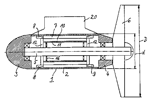
Figure 1 illu.st~rates a longitudinal section of a
propulsion device with air cooling of the winding overhangs of
the stator according to an embodiment of the present invention.
Figure 2 illustrates a longitudinal section of a
propulsion device with spray cooling of the winding overhangs
according to an embodiment= of the present invention.
Detailed Description
The propulsion device according to Figure 1 has a
hydrodynamically designed housing part 1 in the form of a
gondola with a synchronous motor arranged in it, the
synchronous motor having a stator 7 and a rotor 10, and a shaft
20, with the help of which the propulsion device may be mounted
on the bottom of a hull i_rr the manner of a gondola. Housing
part 1 has hollow cylindrical part 2 and end caps 3 and 4,
which carry the bearings of drive shaft 5. Propeller 6 is
arranged on one end of the drive shaft 5.
5

CA 02259193 2001-04-18
20365-3967
Stator 7 of t.hc~ synchronous motor is fitted in a
form-fitting manner into th.e hollow cylindrical housing part 2.
With this part of housing 1 being shrunk-fit onto the stator
core assembly, for example the windings of the stator are
visible in winding overhangs 8 and 9. Rotor 10 of the
synchronous motor is des_Lgned in an essentially known manner as
a permanent-magnet rotor,. resting on drive shaft 5 with a
supporting structure 11. Supporting structure 11 has axial
passages 16.
A fan 12 is provided on drive shaft 5 inside each
winding overhangs 8 and 9. With the help of this fan, ai.r in
the interior of the synchronous motor is stirred up and flows
past winding overhangs 8 and 9. The synchronous motor as a
whole is cooled essentially through hollow cylindrical part 2
of housing 1 releasing heat to the water flowing past it with
the movement of the ship.
In the embodiment according to Figure 2, a ring 13
with a tubular cross section is arranged on each end of the
winding overhangs 8 and 5~ to cool these winding overhangs and
is provided with spray orifices in the direction of the winding
overhangs. Insulating oil. in sump 14 below drive shaft 5 may
be sprayed through these spray orifices, being pumped from the
sump into ring 13 by a pump located outside housing part 1.
Heat is also removed from .insulating oil sump 14 through
housing part 1, as is also from the air stirred up according to
Figure 1. Sump 14 should. not include the air gap of the motor.
Spray rings 13 may be p:rcv:ided in addition to or as an
alternative to fans 12.
Due ~o the fact that the synchronous generator with
its stator is :inserted :in a form-fitting manner into
hydrodynamical:Ly designed housing part 1, and permanent-magnet
rotor 10 takes up less :pace radially than would a squirrel-
6

CA 02259193 2001-04-18
20365-3967
cage rotor, housing pai:t ~ may have a relatively small outside
diameter d, so the ratio of outside diameter d of housing
part 1 to outside diametez~ D of propeller 6 achieves a
relatively small value of 0.35, for example, even if the
synchronous motor is designed for a drive power of 2 to 20 MW
or more.
This design of the new propulsion device does not
depend on whether the gondola is mounted rigidly or rotatably
on the hull. Thus, it i;~ also suitable for bulkhead drives.
7

Dessin représentatif
Une figure unique qui représente un dessin illustrant l'invention.
États administratifs

2024-08-01 : Dans le cadre de la transition vers les Brevets de nouvelle génération (BNG), la base de données sur les brevets canadiens (BDBC) contient désormais un Historique d'événement plus détaillé, qui reproduit le Journal des événements de notre nouvelle solution interne.

Veuillez noter que les événements débutant par « Inactive : » se réfèrent à des événements qui ne sont plus utilisés dans notre nouvelle solution interne.

Pour une meilleure compréhension de l'état de la demande ou brevet qui figure sur cette page, la rubrique Mise en garde , et les descriptions de Brevet , Historique d'événement , Taxes périodiques et Historique des paiements devraient être consultées.

Historique d'événement

Description Date
Le délai pour l'annulation est expiré 2017-06-19
Lettre envoyée 2016-06-20
Inactive : CIB de MCD 2006-03-12
Accordé par délivrance 2001-12-18
Inactive : Page couverture publiée 2001-12-17
Préoctroi 2001-08-21
Inactive : Taxe finale reçue 2001-08-21
Inactive : Lettre officielle 2001-06-28
Modification après acceptation reçue 2001-04-18
Inactive : Taxe de modif. après accept. traitée 2001-04-18
Un avis d'acceptation est envoyé 2001-02-28
Lettre envoyée 2001-02-28
Inactive : Approuvée aux fins d'acceptation (AFA) 2001-02-01
Inactive : CIB attribuée 1999-03-08
Symbole de classement modifié 1999-03-08
Inactive : CIB attribuée 1999-03-08
Inactive : CIB en 1re position 1999-03-08
Inactive : CIB attribuée 1999-03-08
Inactive : Acc. récept. de l'entrée phase nat. - RE 1999-02-23
Demande reçue - PCT 1999-02-19
Toutes les exigences pour l'examen - jugée conforme 1998-12-24
Exigences pour une requête d'examen - jugée conforme 1998-12-24
Demande publiée (accessible au public) 1997-12-31

Historique d'abandonnement

Il n'y a pas d'historique d'abandonnement

Taxes périodiques

Le dernier paiement a été reçu le 2001-05-22

Avis : Si le paiement en totalité n'a pas été reçu au plus tard à la date indiquée, une taxe supplémentaire peut être imposée, soit une des taxes suivantes :

  • taxe de rétablissement ;
  • taxe pour paiement en souffrance ; ou
  • taxe additionnelle pour le renversement d'une péremption réputée.

Veuillez vous référer à la page web des taxes sur les brevets de l'OPIC pour voir tous les montants actuels des taxes.

Titulaires au dossier

Les titulaires actuels et antérieures au dossier sont affichés en ordre alphabétique.

Titulaires actuels au dossier
SIEMENS AKTIENGESELLSCHAFT
Titulaires antérieures au dossier
CHRISTIAN MEYER
PETER HEIN
Les propriétaires antérieurs qui ne figurent pas dans la liste des « Propriétaires au dossier » apparaîtront dans d'autres documents au dossier.
Documents

Pour visionner les fichiers sélectionnés, entrer le code reCAPTCHA :


Pour visualiser une image, cliquer sur un lien dans la colonne description du document. Pour télécharger l'image (les images), cliquer l'une ou plusieurs cases à cocher dans la première colonne et ensuite cliquer sur le bouton "Télécharger sélection en format PDF (archive Zip)" ou le bouton "Télécharger sélection (en un fichier PDF fusionné)".

Liste des documents de brevet publiés et non publiés sur la BDBC .

Si vous avez des difficultés à accéder au contenu, veuillez communiquer avec le Centre de services à la clientèle au 1-866-997-1936, ou envoyer un courriel au Centre de service à la clientèle de l'OPIC.


Description du
Document 
Date
(aaaa-mm-jj) 
Nombre de pages   Taille de l'image (Ko) 
Description 1998-12-24 6 246
Abrégé 1998-12-24 1 55
Dessins 1998-12-24 1 29
Revendications 1998-12-24 2 51
Abrégé 2001-11-15 1 16
Page couverture 2001-11-22 1 46
Dessin représentatif 2001-11-22 1 15
Dessin représentatif 1999-03-23 1 10
Abrégé 2001-04-18 1 16
Description 2001-04-18 7 286
Revendications 2001-04-18 2 54
Page couverture 1999-03-23 1 47
Rappel de taxe de maintien due 1999-02-22 1 111
Avis d'entree dans la phase nationale 1999-02-23 1 202
Courtoisie - Certificat d'enregistrement (document(s) connexe(s)) 1999-02-23 1 117
Avis du commissaire - Demande jugée acceptable 2001-02-28 1 164
Avis concernant la taxe de maintien 2016-08-01 1 180
Correspondance 2001-08-21 1 40
PCT 1998-12-24 10 332