Note : Les descriptions sont présentées dans la langue officielle dans laquelle elles ont été soumises.
z CA 02259736 2001-08-17
MEMBRANE AIR DRYER WITH SCHEME TO REDUCE AIR LOST AS SWEEP
AIR
FIELD OF THE INVENTION
The invention generally re:Lates to gas dryers of
the type that use semipermeable membranes to remove moisture
from gas in which the moisture is suspended. More
particularly, the invention relates to a system that reduces
the amount of gas otherwise lost as sweep gas that is used to
sweep the accumulated moisture away from the membranes of the
gas dryer.
BACKGROUND OF THE IN'rENTION
The following background information is provided to
assist the reader to understand the invention described and
claimed below. Accordingly, any terms used herein are not
intended to be limited to any particular narrow
1
CA 02259736 1999-O1-20
interpretation unless specifically stated otherwise in this
document.
It is well known in the air drying art that the
amount of moisture suspended in any given volume of air is
dependent on both the pressure and temperature of the air
contained in that volume. This relationship between
pressure, volume and temperature is defined by the various
ideal gas laws of thermodynamics. When a quantity of air is
compressed by reducing the volume it occupies, the amount of
moisture that the compressed air can hold is reduced
accordingly, assuming its temperature is held constant. The
temperature of air, however, increases as the air is
compressed, and this temperature increase enables the air to
hold its moisture.
In most compressed air systems, such as those used
in the railroad industry, temperature increases are
undesirable. This is because the compressed air system has
components downstream whose temperatures may be lower than
that of the incoming moisture-laden compressed air. The
moisture in such moisture-laden air tends to condense on the
surfaces of these downstream components and contaminates the
compressed air system and the pneumatic components that it
supplies. Consequently, an aftercooler is typically inserted
2
CA 02259736 1999-O1-20
between the output of the compressor and the intake port of
the air drying system to lower the temperature of the
incoming compressed air. By lowering the temperature, the
aftercooler causes some of the water vapor suspended in the
air to precipitate out of the air in the form of liquid
condensate. This liquid condensate is usually removed from
the air drying system via well known devices such as
separating chambers and coalescing elements. Despite the use
of aftercoolers, separating chambers and coalescing elements,
the compressed air will still hold some water vapor as it is
difficult to remove this remaining moisture solely by
mechanical means. Such mechanical means thus are often used
in conjunction with one of the known air drying methods to
remove this remaining water vapor. Depending on the specific
application and environment in which it is used, an air
drying method may be used alone, without the aforementioned
mechanical means.
There are at least three prior art methods of
drying air that are commonly used to remove water vapor. (1)
Absorbent type air dryers use deliquescent desiccant that
becomes liquid by absorbing moisture suspended in the air.
Deliquescent air dryers typically have no moving parts and
their costs are initially low. These dryers, however,
3
CA 02259736 1999-O1-20
exhibit limited dew point suppression - 20° to 30° F is
common. They also require considerable maintenance, e.g.,
the desiccant must be periodically replaced and the system
manually drained on a regular basis. (2) Adsorbent type air
dryers use regenerative desiccant that temporarily adsorbs
moisture on the surface of its molecules. The moisture
temporarily accumulated by the desiccant is later removed via
a stream of dried air redirected through the desiccant to
purge the moisture to atmosphere. Regenerative dryers are
able to achieve low dew points, but impose high costs
initially and high operating costs thereafter. Their
desiccant towers, in which the desiccant is housed, also must
be serviced periodically. (3) Refrigeration type air dryers
typically require low maintenance and impose low operating
costs, but are not able to achieve low dew points. Dew
points are typically limited to approximately 38° F as a
minimum to prevent freeze ups. Refrigeration type dryers are
used in many industries as a first step in a multi-step
drying system, e.g., before drying the air in desiccant type
air dryer.
Another method of drying air employs the use of
semipermeable membranes to remove moisture from the air in
which the moisture is suspended. These membrane type air
4
CA 02259736 1999-O1-20
dryers have long been used in various industries. Such
membrane type air dryers typically feature a membrane fiber
bundle and a containment vessel or shell in which the bundle
is encased. The membrane fiber bundle is of a type that is
commercially available from Bend Research, Inc. of Bend,
Oregon, U.S.A.
Regarding basic operation of a membrane type air
dryer, air passes through each membrane in the bundle by a
combination of (i) diffusion through the pores linking the
respective surfaces of a membrane and (ii) permeation through
the material of the membrane. The force that drives the
separation of water vapor from air is the difference between
the pressure of the air on one side of a membrane and the
pressure of air on the other side of the membrane. When air
is compressed, the partial pressures of the various
constituents in the air each increase. Water vapor, of
course, is present in the stream of compressed air that flows
into the inlet of the membrane housing from the source of
compressed air. The partial pressure of the water vapor in
the air stream flowing in the bundle will be greater than
that of the atmospheric air by a factor dependent upon the
compression ratio of the compressor. This difference in the
partial pressure of water vapor on the inside (higher) versus
CA 02259736 1999-O1-20
that on the outside (lower) of the membranes drives the water
vapor through the membranes into the sweep air space defined
between the outside of the bundle and the inner wall of the
containment vessel.
The vessel in which the membrane fiber bundle is
encased also features a drain hole that communicates with the
sweep air space. The sweep air space serves as the conduit
to transport the water vapor that has permeated through the
membranes to the drain hole. It is through this drain hole
that the permeated water vapor is forcibly purged from the
sweep air space by "sweep air." The air stream flowing
through the fiber bundle causes pressure to build within its
membranes. The "sweep air" that is used to purge the
permeated water vapor from the vessel originates within these
pressurized membranes. Composed of light gases including
even hydrogen and helium that are capable of penetrating the
membranes, the sweep air leaks out of the membranes and
forcibly carries with it the permeated water vapor out the
drain hole in the bottom of the vessel. It is for this
reason that the vessel is often referred to as the sweep air
containment vessel. The dried non-permeate air that emerges
from the outlet of the membrane housing, of course, flows
6
CA 02259736 1999-O1-20
into whatever pneumatic components) that the membrane air
dryer is intended to supply.
The membrane type air dryer is typically
incorporated within a compressed air system between the
source of compressed air and a reservoir or other pneumatic
component to which it supplies the compressed dried air. As
shown in Figure 1, a check valve is commonly installed
between the outlet of the dryer and the inlet of the
reservoir to prevent air from flowing back into the dryer
when the source of compressed air is unloaded (i.e., turned
off). When the source of compressed air is loaded, the
compressed air that flows through the fiber bundle will cause
pressure to build within the membranes as described
previously. It is this pressure that is the source of the
sweep air. When the source of compressed air is unloaded,
however, the pressure that has accumulated within the
membranes is largely lost as sweep air as it is continuously
vented from the drain hole of the vessel.
It is well known that on a train locomotive the
compressor is controlled so that compressed air is supplied
to the air system on a periodic basis. Typically, the
locomotive compressor will supply compressed air once every
five minutes for a time of approximately thirty seconds. A
7
CA 02259736 1999-O1-20
membrane type air dryer if incorporated into the air system
of a locomotive would therefore be required to operate
according to this duty cycle. During the thirty second
period when the compressor is loaded (i.e., the drying phase
of the duty cycle), the compressed air that would flow into
the fiber bundle would cause pressure to build within the
membranes as described previously. When turned off during
the inactive phase of its duty cycle, the compressor would be
unloaded for such a long time that much, if not most all, of
the pressure built up within the membranes would be lost as
sweep air. Consequently, when again turned on for the next
thirty second period, the compressor would spend too much of
that time span on merely re-pressurizing the membranes of the
fiber bundle.
The primary disadvantage to this setup is that
sweep air is continuously vented from the vessel of the
membrane type air dryer. It would therefore be desirable to
devise a system that prevents excessive loss of air as sweep
air from the sweep air containment vessel of a membrane type
air dryer.
OBJECTIVES OF THE INVENTION
It is, therefore, a primary objective of the
invention to provide a control system for a membrane type air
8
CA 02259736 1999-O1-20
dryer that reduces the amount of air lost as sweep air by
which the water vapor that has passed through the membranes
of the air dryer is swept away to atmosphere.
Another objective is to reduce the time that the
compressor must take to repressurize the membranes of a
membrane type air dryer during the drying phase of its duty
cycle.
Yet another objective is to incorporate a memory
feature into a membrane type air dryer that enables the air
dryer to resume its drying function generally with the same
amount of internal air pressure that it had when the drying
function was last stopped.
In addition to the objectives and advantages listed
above, various other objectives and advantages will become
more readily apparent to persons skilled in the relevant art
from a reading of the detailed description section of this
document. These other objectives and advantages will become
particularly apparent when the detailed description is
considered along with the attached drawings and with the
appended claims.
SUMMARY OF THE INVENTION
In a presently preferred embodiment, the invention
provides a control system that reduces the amount of gas lost
9
CA 02259736 1999-O1-20
as sweep gas from a membrane type gas dryer. The membrane
gas dryer is of the type that features an inlet end that
receives moisture laden gas from a compressor, an outlet end
from which dried gas is discharged to a pneumatic component
and a drain port from which permeate sweep gas inclusive of
permeate water vapor is expelled from the gas dryer. The
control system includes a purge valve that is connected to
the drain port of the gas dryer and a means for controlling
the purge valve. The purge valve has a pilot port that
responds to pressure by closing the purge valve thereby
preventing the permeate sweep gas from exhausting to
atmosphere through the drain port. The means for controlling
controls the purge valve such that (i) when the compressor is
unloaded, the dried gas from the pneumatic component is
allowed to flow to and pressurize the pilot port thereby
closing the purge valve and preventing the permeate sweep gas
from exhausting to atmosphere and (ii) when the compressor is
loaded, the pilot port is vented to atmosphere thereby
opening the purge valve and allowing the permeate sweep gas
to exhaust to atmosphere via the drain port of the membrane
type gas dryer.
~ _~,' CA 02259736 2001-10-10
BRIEF DESCRIPTION OF THE DRAWINGS
Figure 1 is a schematic view of a membrane type air
dryer within the compressed air system of a train locomotive.
Figure 2 is a schematic view of a membrane type air
dryer in the compressed air system of a locomotive
incorporating the control system according to the invention.
DETAILED DESCRIPTION OF THE INVENTION
Before describing the invention in detail, the
reader is advised that, for the sake of clarity and
understanding, identical components having identical
functions have been marked where possible with the same
reference numerals in each of the Figures provided in this
document.
Figure 1 illustrates one way in which to
incorporate a membrane type air dryer within the compressed
air system of a railroad locomotive. The membrane type air
dryer 1 features a membrane fiber bundle 2 encased within a
containment vessel 3. During the drying phase of the
aforementioned duty cycle, the inlet end 4 of the membrane
type air dryer 1 receives moisture-laden air from a
compressor 20 either directly or indirectly via other air
drying components situated between the compressor 20 and the
membrane air dryer. Due to the incoming air stream,
11
CA 02259736 1999-O1-20
pressure quickly builds in the membranes of the fiber bundle
2. The sweep air leaks through the membranes carrying with
it the permeate water vapor into the sweep air space 9 of
vessel 3. From the drain port 6, the sweep air inclusive of
the permeate water vapor is expelled to atmosphere. From the
outlet end 5 of the air dryer, dried non-permeate air is
discharged to a reservoir 7 or other suitable pneumatic
components.
Figure 1 also shows a check valve 8 installed
between the outlet end 5 of the dryer and the inlet of
reservoir 7. The check valve 8 prevents dried air from
flowing back into the dryer when the locomotive compressed
air system is in the inactive phase of its duty cycle.
During this inactive phase, the pressure that had built up
within the membranes of the fiber bundle 2 during the
previous drying phase continues to drop becawse sweep air
continues to leak through the membranes and to atmosphere via
drain port 6 of the sweep air containment vessel 3. As the
duty cycle is typically set at thirty seconds of drying once
every five minutes, the inactive phase is much longer than
the drying phase of the duty cycle. The membranes of the
fiber bundle 2 thus lose much, if not all, of their pressure
during the inactive phase of the duty cycle. Too much of the
12
CA 02259736 2001-08-17
next drying phase must then be devoted to repressurizing the
membranes of the fiber bundle 2 before the dryer can again
operate efficiently.
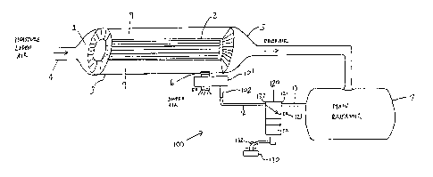
Referring now to a presently preferred embodiment
of the invention, Figure 2 illustrates a control system,
generally designated 100, for a membrane type air dryer 1
that overcomes the deficiencies inherent in the design
illustrated in Figure 1. The control system 100 includes a
purge valve 101, a magnet valve 120 and a pressure switch
130. The purge valve 101 has an inlet: connected to the drain
port 6 of containment vessel 3, an outlet exposed to
atmosphere and a pilot port 102. In response to a preset
pressure received at pilot port 102 from interconnective pipe
12, the purge valve 101 closes communication between its
inlet and outlet. When closed due t:o the preset pressure,
the purge valve 101 prevents the permeate sweep air from
exhausting to atmosphere via drain port 6 of containment
vessel 3.
Connected between interconnective pipes 12 and 13,
the magnet valve 120 is a three way valve situated between
the reservoir 7 and the pilot port 1.02 of purge valve 101.
Specifically, the magnet valve 120 is connected at its supply
port 121 to pipe 13 from the main :reservoir 7 and at its
13
CA 02259736 2001-08-17
delivery port 122 to pipe 12 from t:he pilot port of purge
valve 101. The exhaust port 123 of magnet valve 120 is open
to atmosphere. Preferably controlled by pressure switch 130
or other suitable device, the magnet valve may be commanded
to assume either a normally closed (deenergized) state or an
open (energized) state. Figure 2 shows the magnet valve 120
in its normally closed state in which its delivery and
exhaust ports 122 and 123 communicate. In its open state
(not shown), the supply and delivery ports 121 and 122
communicate. The pressure switch 130 controls the magnet
valve 120 by being responsive to the loading of the
compressed air system of the locomotive.
Regarding the particulars of how purge valve 101
and magnet valve 120 are controlled, when the compressor 20
is unloaded, the pressure switch 130 energizes the magnet
valve 120 via electrical lines 132. The magnet valve 120
responds by assuming the open state _Ln which the supply and
delivery ports 121 and 122 communicate. This allows the
dried permeate air previously stored in reservoir 7 to flow
through pipe 13, magnet valve 120 and pipe 12 to the pilot
port 102 of purge valve 101. With its pilot port
pressurized, the purge valve 101 closes thereby preventing
the permeate sweep air from exhausting to atmosphere via
14
CA 02259736 2001-08-17
drain port 6 of the sweep air Containment vessel 3. The
sweep air is thus retained within the sweep air containment
vessel 3 when the compressed air system is unloaded. When
the compressor 20 again becomes loaded, the pressure switch
130 deenergizes the magnet valve 120. The magnet valve
responds by again assuming its normally closed state in which
its delivery and exhaust ports 122 and 123 Communicate. This
allows the pilot port 102 to vent to atmosphere through pipe
12 and the internal passageway formed in magnet valve 120 by
the aligning of its delivery and exhaust ports 122 and 123.
Without pressure impinging on its pilot port, the purge valve
101 opens thereby allowing the permeate sweep air to exhaust
from the drain port 6 to atmosphere.
Taken together, magnet valve 120 and pressure
switch 130 may essentially be considered as a means through
which to control the purge valve 101 of the invention. It
should be understood that this Coni~rol means, of Course,
could also be implemented using various other known
techniques and devices in lieu of the air piloted purge valve
101, magnet valve 120 and pressure switch 130. The purge
valve, for example, could take the form of a magnet valve
controlled by such a pressure switch.
CA 02259736 2001-08-17
By itself, the magnet valve 120 is a device whose
construction and operation is generally well known in the air
drying art. The pressure switch itself may be of the type
commonly used in the field of pneumatics. For example, it is
well known that compressors are often equipped with a
governor - a mechanism by which to regulate automatically the
operation of the compressor. This governor typically features
a pressure switch of the type appropriate to this invention.
then the compressor 20 is unloaded, the pressure switch in
the governor senses the unloaded state of the compressor 20
and can provide an electrical signal that can be used to
energize the magnet valve 120 of the invention.
It should be apparent that the invention could be
implemented in a variety of air drying systems and need not
be confined solely to railroad industry applications. It is,
however, particularly well suited for use with train
locomotive compressed air systems that are equipped with
membrane type air dryers. This is because train compressed
air systems are operated according to the aforementioned two
phase duty cycle. Specifically, the control system 100 of
the invention essentially endows a membrane type air dryer
with a memory feature. This feature enables the air dryer to
resume its next drying phase generally with the same amount
16
CA 02259736 2001-08-17
of internal air pressure that it had when the previous drying
phase stopped. This reduces the amount of time that the
compressor 20 must take to repressurize the membranes during
the next drying phase. More significantly, it reduces the
amount of air that the air dryer would otherwise lose as
sweep air absent the invention.
The presently preferred embodiment for carrying out
the invention has been set forth in detail according to the
Patent Act. Those persons of ordinary skill in the art to
which this invention pertains may nevertheless recognize
various alternative ways of practicing the invention without
departing from the spirit and scope of the appended claims.
Those of such skill will also recognize that the foregoing
description is merely illustrative and not intended to limit
any of the ensuing claims to any particular narrow
interpretation.
Accordingly, to promote the progress of science and
useful arts, I secure for myself by Letters Patent exclusive
rights to all subject matter embraced by the following claims
for the time prescribed by the Patent Act.
17