Sélection de la langue

Search

Sommaire du brevet 2260515 

Énoncé de désistement de responsabilité concernant l'information provenant de tiers

Une partie des informations de ce site Web a été fournie par des sources externes. Le gouvernement du Canada n'assume aucune responsabilité concernant la précision, l'actualité ou la fiabilité des informations fournies par les sources externes. Les utilisateurs qui désirent employer cette information devraient consulter directement la source des informations. Le contenu fourni par les sources externes n'est pas assujetti aux exigences sur les langues officielles, la protection des renseignements personnels et l'accessibilité.

Disponibilité de l'Abrégé et des Revendications

L'apparition de différences dans le texte et l'image des Revendications et de l'Abrégé dépend du moment auquel le document est publié. Les textes des Revendications et de l'Abrégé sont affichés :

  • lorsque la demande peut être examinée par le public;
  • lorsque le brevet est émis (délivrance).
(12) Demande de brevet: (11) CA 2260515
(54) Titre français: CONDUIT ELECTRIQUE MODULAIRE
(54) Titre anglais: MODULAR CABLE GUIDE SYSTEM
Statut: Réputée abandonnée et au-delà du délai pour le rétablissement - en attente de la réponse à l’avis de communication rejetée
Données bibliographiques
(51) Classification internationale des brevets (CIB):
  • F16L 21/06 (2006.01)
  • B29C 45/17 (2006.01)
  • F16L 3/26 (2006.01)
(72) Inventeurs :
  • VAN BOEKEL, FRANCISCUS ANTONIUS JOSEF
(73) Titulaires :
  • DYNISCO HOTRUNNERS B.V.
(71) Demandeurs :
  • DYNISCO HOTRUNNERS B.V.
(74) Agent: MCCARTHY TETRAULT LLP
(74) Co-agent:
(45) Délivré:
(22) Date de dépôt: 1999-01-28
(41) Mise à la disponibilité du public: 1999-07-28
Requête d'examen: 2003-12-29
Licence disponible: S.O.
Cédé au domaine public: S.O.
(25) Langue des documents déposés: Anglais

Traité de coopération en matière de brevets (PCT): Non

(30) Données de priorité de la demande:
Numéro de la demande Pays / territoire Date
98200249.5 (Office Européen des Brevets (OEB)) 1998-01-28

Abrégés

Abrégé anglais


The invention relates to a modular cable guide system for use in an
injection moulding apparatus comprising
- at least one first cable guide conduit,
- at least one connector having a sleeve for fitting around a first
end of the first cable guide conduit, clamping means for tightening the
sleeve around the first cable guide conduit for forming a clamping
connection with the conduit and a coupling member for connecting the
connector to a machine part or to another cable guide conduit, and
- a second cable guide conduit having a number of regularly spaced
connecting holes for receiving coupling elements for connecting the
second guide conduit to the machine part.
The system according to the invention can be easily installed and
can be made to the right size and placed into the right configurations
upon installation.

Revendications

Note : Les revendications sont présentées dans la langue officielle dans laquelle elles ont été soumises.


7
Claims
1. Modular cable guide system (1) for use in injection moulding
apparatus comprising:
- at least one first cable guide conduit (13),
- at least one connector (17,18,53,60,72) having a sleeve (54,75)
for fitting around a first end of the first cable guide conduit (13),
clamping means (22,23,30,31,33) for tightening the sleeve around the
first cable guide conduit (13) for forming a clamping connection with
the cable guide conduit and a coupling member (27,35,36;55;75') for
connecting the connector to a machine part (2) or to another cable guide
conduit (13'), and
- a second cable guide conduit (14) having a number of regularly
spaced connecting holes (39,40) for receiving coupling elements
19,20,41,42) for connecting the second cable guide conduit (14) to the
machine part.
2. Cable guide system (1) according to claim 1, characterised in
that, the connector (60) comprises a first segment (61) comprising the
sleeve, a plate (62) extending from the sleeve and comprising one of
either two pins (63,64) or two slots (67,68) located on a circular track
and a second segment (65) comprising a plate (66) extending parallel to
the plate (62) of the first segment (61) and comprising the other of the
two pins (63,64) or the two slots (67,68) and a coupling member or a
sleeve for connecting the second segment (65) to a machine part (2) or
to further guide conduit (13'), the pins (63,64) projecting through the
slots (67,68) such that the segments (61,65) can be displaced with
respect to one another, the pins (63,64) further comprising locking
means, for fixing the relative positions of the segments (61,65).
3. Cable guide system (1) according to claim 1 or 2, characterised
in that, the cable guide conduits (13,14) and the sleeves (54,75) are of
substantially rectangular cross-sectional shape.
4. Cable guide system (1) according to claim 3, characterised in
that, the sleeve (54,75) comprises two upstanding oppositely located

8
walls (28,29) and a clamping plate (22,33) bridging the walls, the
clamping plate (22,33) being connected to the walls (28,29) by means of
bolts (31).
5. Cable guide system (1) according to any of the previous claims,
characterised in that, the coupling member (55) comprises a plate (56)
transverse to the cable guide conduit (13).
6. Cable guide system (1) according to any one of claim 1 to 4,
characterised in that, the coupling member comprises a plate (27)
parallel to the cable guide conduit (13).
7. Cable guide system (1) according to any of the previous claims,
characterised in that, the coupling elements (41,42) comprise a first
part (43,44) having a screw thread and a gripping head (47,48) for being
threaded into the machine part and comprising in the gripping head an
internal screw thread for receiving a second coupling element part
(45,46) having an external screw thread and a clamping head (49,50).
8. Cable guide system (1) according to any of the previous claim,
comprising a connector plate (16) for attaching to a wire receiving box
(15), the connector plate carrying a connector (17) for receiving a
cable guide conduit (13) substantially perpendicularly to the connector
plate (16).
9. Connector (17,18,53,60,72) for use in a cable guide system
according to any of the previous claims, comprising a sleeve (54,75) for
fitting around a first end of a cable guide conduit (13), clamping means
(22,23,30,31,33) for tightening the sleeve (54,75) around the first
cable guide conduit for forming a clamping connection with the cable
guide conduit and a coupling member (27,35,36;53,75) for connecting the
connector to a machine part (2) or to another cable guide conduit (13').
10. Connector according to claim 9, characterised in that, the
connector (60) comprises a first segment (61) comprising the sleeve, a
plate (62) extending from the sleeve and comprising one of either two
pins (63,64) or two slots (67,68) located on a circular track and a
second segment (65) comprising a plate (66) extending parallel to the

9
plate (62) of the first segment (61) and comprising the other of the two
pins (63,64) or the two slots (67,68) and a coupling member or a sleeve
for connecting the second segment (65) to a machine part (2) or to
further guide conduit (13'), the pins (63,64) projecting through the
slots (67,68) such that the segments (61,65) can be displaced with
respect to one another, the pins (63,64) further comprising locking
means, for fixing the relative positions of the segments (61,65).
11. Wire receiving box having a connector plate for use in a cable
guide system according to claim 8, the wire receiving box having a
connector plate carrying a connector (17) for receiving a cable guide
conduit (13) substantially perpendicularly to the connector plate (16).

Description

Note : Les descriptions sont présentées dans la langue officielle dans laquelle elles ont été soumises.

CA 02260515 1999-O1-28
Modular cable guide system.
The invention relates to a modular cable guide system for use in
an injection moulding apparatus.
In injection moulding apparatus, the molten thermoplastic
material is supplied to a moulding cavity via a system of conduits.
These conduits are built into a mould which is maintained at a
relatively low temperature to allow the molten thermoplastic material to
cool and solidify. Systems wherein the conduits are heated, so-called
"hot runner systems" are extensively used. The hot runner system
comprises a central injection opening for injecting the plastic material
into a manifold. A number of nozzles is connected to the manifold for
injecting the molten thermoplastic material into the mould cavity. For
maintaining the hot runner system at a high temperature (such as for
instance 250~C), electrical heating elements and thermocouples for
measuring the temperature are distributed along the manifold. These
heating elements and thermocouples comprise a large number of connecting
wires which leave the manifold and which have to be guided to connector
boxes outside the manifold area.
In general the central injection area, the manifolds and each
nozzle comprises one or more heating elements and thermocouples. It is
presently known to guide the connecting wires of a11 these elements via
a single central channel to a connector- and/or control box. Manifold
systems comprising four nozzles can comprise twelve controlled heating
zones which include per zone a ground wire, two supply wires and two
thermocouple wires, which amounts to a number of 60 connecting wires in
total. Larger systems however are also common.
In order to avoid an irregular pattern of wires on the manifold
system, to protect the connecting wires from mechanical damage and to
isolate the wires from heat, use is made of cable guides. These cable
guides are tubes through which the connecting wires are guided to the
connector box outside of the manifold system. These cable guides have to
be taylor made for each system and are each time designed according to
specific demands as hot runner systems are client specific. The cable
guides are separately drawn and constructed. This is a complex process
which is relatively time-consuming and which has to be carried out each
time in detail when designing a different injection moulding apparatus.
It is therefore an object of the present invention to provide a

CA 02260515 1999-O1-28
2
cable guide system which can be easily applied to different injection
moulding configurations with a minimum of predesign, which is reliable,
which is simple and which can be easily installed.
Thereto the cable guide system according to the present invention
is characterised in that it comprises
- at least one first cable guide conduit,
- at least one connector having a sleeve for fitting around a first
end of the guide conduit, clamping means for tightening the sleeve
around the first conduit for forming a clamping connection with the
conduit and a coupling member for connecting the connector to a machine
part or to another cable guide conduit, and
- a second cable guide conduit having a number of regularly spaced
connecting holes for receiving coupling elements for connecting the
second guide conduit to the machine part.
The first cable guide conduit can bridge the space between the
manifold and the connector box. As the ends of the first cable guide
conduit fit into the sleeve of the connector, no separate connecting
elements are present on the cable guide conduit itself so that it can be
made to the right size by simply cutting off a part of the guide conduit
from for instance a continuous stock of cable guide conduit. After
having been cut or sawn to the right size, both ends of the cable guide
conduit are clamped into a respective connector sleeve, one of which may
be connected to for instance the connector- or control box, the other
being connected to a machine part such as a manifold. From the first
cable guide conduit, the wires are fed into the second guide conduit
which is attached onto the machine part and which may bridge the space
from the edge of manifold to the injection nozzles. As the second guide
conduit comprises regularly spaced connecting holes, it can again be
made to the right size by cutting off a part, for instance from a stock
guide conduit of longer length. The pattern of holes corresponds with
the pattern of threaded connecting bores on the machine part, such that
any cut-off length of second cable conduit can be attached to the
machine parts in a position corresponding with the pattern of holes
thereon.
The modular cable guide system according to the present invention
can be very easily installed because the cable guide conduits can be cut
to the right size on site during installation. As no coupling elements
are comprised on the first cable guide conduit, it can be cut at any

CA 02260515 1999-O1-28
3
place along its length and be clampingly engaged with the connectors.
The same freedom in length dimensions is obtained for the second guide
conduit by the regularly spaced connecting holes therein. Both cable
guide conduits may comprise a tubular shape, or can comprise a separate
lid which may be clipped on each cable guide conduit. The connectors may
comprise coupling members located on a face parallel to the cable guide
conduits for attaching to a side surface of the machine part or may
comprise coupling members on a surface transverse to the first cable
guide conduit for connecting to an end face of the machine part or
manifold.
In a preferred embodiment, the connector comprises a first
segment comprising the sleeve, a plate extending from the sleeve and
comprising one of either two pins or two slots located on a circular
track and a second segment comprising a plate extending parallel to the
plate of the first segment and comprising the other of the two pins or
the two slots and a coupling member or a sleeve for connecting the
second segment to a machine part or to further guide conduit, the pins
projecting through the slots such that the segments can be displaced
with respect to one another, the pins further comprising locking means
for fixing the relative positions of the segments. By the above
construction, the two connector segments can rotate with respect to one
another wherein the pins are guided along the circular slots. When in
the right angular position, the locking means, which may comprise nuts
around the threaded ends of the pins, may be tightened for fixing the
connector segments relative to one another. In this way the cable guide
conduits may be interconnected at a large number of angular positions.
Each connector sleeve may comprise two upstanding oppositely
located walls and a clamping plate bridging these walls. The clamping
plate is connected to the walls by means of bolts. In this way a very
secure connection to the end of each cable guide conduit is obtained.
The second cable guide conduit may be connected to the machine
part by coupling members comprising a first part having a screw thread
and a gripping head for being threaded into the machine part and
comprising in the gripping head an internal screw thread for receiving a
second coupling element part having an external screw thread and a
clamping head. Firstly the first parts are put into place in threaded
bores on the machine part in a pattern corresponding to the holes on the
second guide conduit. Thereafter the second guide conduit is placed onto

CA 02260515 1999-O1-28
4
the first members and is fixed thereafter by inserting the second
coupling member parts into the first parts.
An exemplary embodiment of a modular cable guide system according
to the present invention will be described in detail herebelow with
reference to the accompanying drawings. In the drawings:
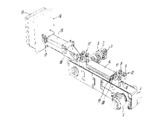
Figure 1 shows a perspective view of a modular cable guide system
according to the present invention,
Figure 2 shows a partly exploded view of a connector box, the
first cable guide conduit and two connectors according to the present
invention,
Figure 3 shows a perspective view of a second cable guide conduit
according to the present invention,
Figure 4 shows a modular cable guide system comprising a
connector with its coupling members placed in a plane transverse to the
cable guide conduit,
Figure 5 shows a connector having two segments allowing angular
adjustment of the cable guide conduits with respect to a machine part,
and
Figure 6 shows a connector having two segments allowing angular
adjustment of two interconnected cable guide conduits.
Figure 1 shows a cable guide system 1 which is connected to a
manifold 2 of a hot runner injection moulding device. The manifold 2
comprises an injection moulding nozzle 3 and a central nozzle 4 which
receives the molten thermoplastic material from an extruder. The nozzle
3 is with its lower end 5 connected to a mould cavity, which is not
shown in figure 1. Around each nozzle 3,4 an electrical heating element
7 is placed in the form of a clamping bush. For each heating element 7
two supply wires 8,9, a ground wire 10 and a thermocouple wire 11 exit
from the manifold 2. Furthermore, there may be heating wires embedded in
the manifold material for maintaining the manifold temperature around
the supply ducts of the molten thermoplastic material at the desired
level. These heating wires are not shown in this figure. The first group
of electrical wires 12 is lead through a second cable guide conduit 14
to a first cable guide conduit 13, together with a second group of
electrical wires 12' and from there to a wire receiving box 15, which
may be a connector- or control unit comprising for instance an
electrical power supply, a microprocessor for reading out the
thermocouple signals and for controlling the power supply, etc.

CA 02260515 1999-O1-28
As can be seen from figure 1, the first cable guide conduit 13 is
on one side connected to a connector plate 16 of the wire receiving box
via a connector 17. The second end of the cable guide conduit 13 is
connected to the manifold 2 via connector 18. The second cable guide
5 conduit 14 is connected to the manifold 2 via coupling elements 19,20
which are screwed into the manifold 2 and which project through holes in
the bottom of the cable guide conduit 14, which holes are spaced at
regular intervals along the bottom of the cable guide conduit 14.
As can be seen in figure 2, the connector 17 on the connector
10 plate 16 comprises a U-shaped part 21 and a clamping plate 22 connected
to the U-shaped part 21 via bolts 23. The first end 25 of the cable
guide conduit 13 clampingly fits in the sleeve which is formed by the U-
shaped part 21 and the clamping plate 22. By tightening the bolts 23,
the cable guide conduit 13 is securely and accurately affixed to the
15 connector plate 16. The connector 18 comprises a bottom plate 27 and two
oppositely located upstanding side walls 28,29. Again, threaded bushes
30 are connected to the side walls 28,29 for receiving bolts 31 for
connecting the clamping plate 33 to the side walls 28,29. The second end
26 of the cable guide conduit 13 can be clampingly engaged in the sleeve
formed by the bottom plate 27, the side walls 28,29 and the clamping
plate 33. The bottom plate 29 comprises coupling elements 35,36 for
attaching to the manifold 2.
Although the first cable guide conduit 13 can be formed of a
single piece of tubular material, it is preferred that the cable guide
conduit 13 comprises a "snap on" lid 36 allowing access to the cables,
also when the cable guide conduit 13 is mounted in place.
Figure 3 shows the second cable guide conduit 14 comprising a
lower part 37 and a lid 38. The lower part 37 is provided with regularly
spaced connecting holes 39,40. The second cable guide conduit 14 is
connected to the manifold by means of coupling elements 41,42 each
comprising a first part 43,44 and a second part 45,46. The first parts
43,44 each comprise a threaded end and a gripping head 47,48. The first
parts can be mounted in positions on the manifold 2 corresponding to the
pitch of the regularly spaced holes 39,40 in the lower part 37 of the
cable guide conduit 14. The gripping heads 47,48 are hollow and comprise
an internal thread for receiving the threaded shafts of the second parts
45,46. The clamping heads 49,50 of the second part 45,46 affix the lower
part 47 of the cable guide conduit 14 against the first parts 43,44 of

CA 02260515 1999-O1-28
6
the coupling elements 41,42.
Figure 4 shows an embodiment wherein a connector 53 comprises a
sleeve 54 around the second end 26 of the first cable guide conduit 13.
The coupling member 55 of the connector 53 comprises a plate 56,
transverse to the length direction of the cable guide conduit 13.
Coupling elements 57 are located in the transverse plate 56 such that
the connector 53 can be fixed to an end face of a machine part such as
the manifold 2 shown in figure 1.
Figure 5 shows an embodiment of a connector wherein the second
end 26 of the cable guide conduit 13 is connected to a first segment 61
of the connector 60. The first segment 61 comprises a first plate 62
having two pins 63,64 projecting perpendicularly from the plate 62. A
second segment 65 of the connector 60 comprises a plate 66 having two
slots 67,68 located on a circular track. The second segment 65 is
connected via coupling elements 69,70 to the manifold 2. By rotating the
second segment 65 with respect to the first segment 61, the angle a
between the cable guide conduit 13 and the manifold 2 can be varied
between 0 degrees and 90 degrees. At the end of the pins 63,64, screws
are provided for tightening the plate 66 against the plate 62 and for
fixing the relative angular positions of the cable guide conduit 13 and
the manifold 2.
Finally, figure 6 shows a connector 72 having two similarly
shaped segments 73,74. In this case both segments 73,74 comprise a
sleeve 75,75' in which end parts of a first and a second cable guide
conduit 13, 13' are received respectively. By means of the two sections
73,74 the relative angle a between the cable guide conduits 13 and 13'
can be varied.

Dessin représentatif
Une figure unique qui représente un dessin illustrant l'invention.
États administratifs

2024-08-01 : Dans le cadre de la transition vers les Brevets de nouvelle génération (BNG), la base de données sur les brevets canadiens (BDBC) contient désormais un Historique d'événement plus détaillé, qui reproduit le Journal des événements de notre nouvelle solution interne.

Veuillez noter que les événements débutant par « Inactive : » se réfèrent à des événements qui ne sont plus utilisés dans notre nouvelle solution interne.

Pour une meilleure compréhension de l'état de la demande ou brevet qui figure sur cette page, la rubrique Mise en garde , et les descriptions de Brevet , Historique d'événement , Taxes périodiques et Historique des paiements devraient être consultées.

Historique d'événement

Description Date
Demande non rétablie avant l'échéance 2008-01-28
Le délai pour l'annulation est expiré 2008-01-28
Réputée abandonnée - omission de répondre à un avis sur les taxes pour le maintien en état 2007-01-29
Lettre envoyée 2004-01-20
Requête d'examen reçue 2003-12-29
Exigences pour une requête d'examen - jugée conforme 2003-12-29
Toutes les exigences pour l'examen - jugée conforme 2003-12-29
Inactive : Page couverture publiée 1999-08-02
Demande publiée (accessible au public) 1999-07-28
Symbole de classement modifié 1999-03-24
Inactive : CIB en 1re position 1999-03-24
Inactive : CIB attribuée 1999-03-24
Inactive : CIB attribuée 1999-03-23
Inactive : Certificat de dépôt - Sans RE (Anglais) 1999-03-03
Exigences de dépôt - jugé conforme 1999-03-03
Demande reçue - nationale ordinaire 1999-03-03

Historique d'abandonnement

Date d'abandonnement Raison Date de rétablissement
2007-01-29

Taxes périodiques

Le dernier paiement a été reçu le 2006-01-19

Avis : Si le paiement en totalité n'a pas été reçu au plus tard à la date indiquée, une taxe supplémentaire peut être imposée, soit une des taxes suivantes :

  • taxe de rétablissement ;
  • taxe pour paiement en souffrance ; ou
  • taxe additionnelle pour le renversement d'une péremption réputée.

Veuillez vous référer à la page web des taxes sur les brevets de l'OPIC pour voir tous les montants actuels des taxes.

Historique des taxes

Type de taxes Anniversaire Échéance Date payée
Taxe pour le dépôt - générale 1999-01-28
Enregistrement d'un document 1999-01-28
TM (demande, 2e anniv.) - générale 02 2001-01-29 2000-12-19
TM (demande, 3e anniv.) - générale 03 2002-01-28 2001-11-27
TM (demande, 4e anniv.) - générale 04 2003-01-28 2003-01-07
Requête d'examen - générale 2003-12-29
TM (demande, 5e anniv.) - générale 05 2004-01-28 2004-01-23
TM (demande, 6e anniv.) - générale 06 2005-01-28 2005-01-25
TM (demande, 7e anniv.) - générale 07 2006-01-30 2006-01-19
Titulaires au dossier

Les titulaires actuels et antérieures au dossier sont affichés en ordre alphabétique.

Titulaires actuels au dossier
DYNISCO HOTRUNNERS B.V.
Titulaires antérieures au dossier
FRANCISCUS ANTONIUS JOSEF VAN BOEKEL
Les propriétaires antérieurs qui ne figurent pas dans la liste des « Propriétaires au dossier » apparaîtront dans d'autres documents au dossier.
Documents

Pour visionner les fichiers sélectionnés, entrer le code reCAPTCHA :


Pour visualiser une image, cliquer sur un lien dans la colonne description du document. Pour télécharger l'image (les images), cliquer l'une ou plusieurs cases à cocher dans la première colonne et ensuite cliquer sur le bouton "Télécharger sélection en format PDF (archive Zip)" ou le bouton "Télécharger sélection (en un fichier PDF fusionné)".

Liste des documents de brevet publiés et non publiés sur la BDBC .

Si vous avez des difficultés à accéder au contenu, veuillez communiquer avec le Centre de services à la clientèle au 1-866-997-1936, ou envoyer un courriel au Centre de service à la clientèle de l'OPIC.


Description du
Document 
Date
(aaaa-mm-jj) 
Nombre de pages   Taille de l'image (Ko) 
Dessin représentatif 1999-08-02 1 18
Page couverture 1999-08-02 1 46
Description 1999-01-28 6 323
Abrégé 1999-01-28 1 22
Revendications 1999-01-28 3 111
Dessins 1999-01-28 3 82
Courtoisie - Certificat d'enregistrement (document(s) connexe(s)) 1999-03-03 1 117
Certificat de dépôt (anglais) 1999-03-03 1 165
Rappel de taxe de maintien due 2000-10-02 1 110
Rappel - requête d'examen 2003-09-30 1 112
Accusé de réception de la requête d'examen 2004-01-20 1 174
Courtoisie - Lettre d'abandon (taxe de maintien en état) 2007-03-26 1 175
Correspondance 1999-02-08 14 538
Taxes 2003-01-07 1 32
Taxes 2001-11-27 1 33
Taxes 2000-12-19 1 33
Taxes 2004-01-23 1 26
Taxes 2005-01-25 1 25
Taxes 2006-01-19 1 23