Note : Les descriptions sont présentées dans la langue officielle dans laquelle elles ont été soumises.
CA 02260714 1999-02-04
WELLBORE FLUID RECOVERY
SYSTEMS & METHODS
BACKGROUND OF THE INVENTION
Field Of The invention
This invention is directed to systems and methods for the recovery of fluid
components from fluids used in wellbore operations. In certain particular
embodiments this invention is directed to systems and methods for recovering
base fluids from wellbore drilling and completion fluids, such base fluids
including water and soluble additives, diesel, synthetic oils, mineral oils,
brine,
metal salt and other additives.
Descriation of Related Art
Fluids used in wellbore operations can be complex mixtures with various
components present in precise amounts. In conventional rotary drilling, a
borehole is advanced down from the surface of the earth (or bottom of the sea)
by rotating a drill string having a drill bit at its lower end. Sections of
hollow drill
pipe are added to the top of the drill string, one at a time, as the borehole
is
advanced in increments. In its path downward, the drill bit may pass through a
number of strata before the well reaches the desired depth. Each of these
subsurface strata has associated with it physical parameters, e.g., fluid
content,
hardness, porosity, pressure, inclination, etc., which make the drilling
process a
constant challenge. Drilling through a stratum produces significant amounts of
rubble and frictional heat; each of which must be removed if efficient
drilling is
to be maintained, in typical rotary drilling operations, heat and rock chips
are
removed by the use of a fluid known as drilling fluid or drilling mud.
Drilling mud
is circulated down through the drill string, out through orifices in the drill
bit where
the mud picks up rock chips and heat, and returns up the annular space between
the drill string and the borehole wall to the surface, the mud is, typically,
sieved
on the surface, reconstituted, and pumped back down the drill string.
Drilling mud may be as simple in composition as clear water, but more
likely it is a complicated mixture of various components, e.g., but not
limited to,
clays, thickeners, and weighting agents. The characteristics of the drilled
geologic strata and, to some extent, the nature of the drilling apparatus
determine the physical parameters of the drilling fluid. For instance, the
drilling
CA 02260714 1999-02-04
_2_
mud must be capable of carrying the rock chips to the surface from the
drilling
site. Shale-like rocks often produce chips which are flat. Sandstones are not
quite so likely to produce a flat chip. The drilling fluid must be capable of
removing either type of chip. Conversely, the mud must have a viscosity which
will permit it to be circulated at high rates without excessive mud pump
pressures.
In the instance where a high pressure layer, e.g., a gas formation, is
penetrated, the density of the drilling mud must be increased to the point
such
that the hydrostatic or hydraulic head of the mud is greater than the downhole
(or "formation") pressure. This prevents gas leakage out into the annular
space
surrounding the drill pipe and lowers the chances for the phenomenon known as
"blowout" in which the drilling mud is blown from the well by the formation
gas.
Finely ground barite (barium sulfate) is the additive most widely used to
increase
the specific gravity of drilling mud; although, in special circumstances, iron
ore,
lead sulfide ferrous oxide, or titanium dioxide may also be added.
In strata which are very porous or are naturally fractured and which have
formation pressures comparatively lower than the local pressure of the
drilling
mud, another problem occurs. The drilling fluid, because of its higher
hydrostatic
head, will migrate out into the porous layer rather than completing its
circuit to
the surface. This phenomenon is known as "lost circulation." A common solution
to this problem is to add a lost circulation additive such as gilsonite.
Fluid loss control additives may be included such as one containing either
bentonite clay (which in turn contains sodium montmorillonite) or attapulgite,
commonly known as salt gel. If these clays are added to the drilling mud in a
proper manner, they will circulate down through the drill string, out the
drill bit
nozzles, and to the site on the borehole wall where liquid from the mud is
migrating into the porous formation. Once there, the clays, which are
microscopically plate-like in form, form a filter cake on the borehole wall.
Polymeric fluid control agents are also well known. As long as the filter cake
is
intact, very liquid will be lost into the formation.
The properties required in drilling mud constantly vary as the borehole
progresses downward into the earth. In addition to tile various materials
already
CA 02260714 1999-02-04
-3-
noted, such substances as tannin-containing compounds (to decrease the mud's
viscosity), walnut shells (to increase the lubricity of tile mud between the
drillstring and the borehole wall), colloidal dispersions, e.g., search, gums,
carboxy-methyl-cellulose (to decrease the tendency of the mud to form
excessively thick filter cakes on the wall of the borehole), and caustic soda
(to
adjust the pH of tile mud) are added as the need arises.
The fluid used as drilling mud is a complicated mixture tailored to do a
number of highly specific jobs.
Once the hole is drilled to the desired depth, tile well must be prepared
for production. The drill string is removed from the borehole and the process
of
casing and cementing begins.
A well that is several thousand feet long may pass through several
different hydrocarbon producing formations as well as a number of water
producing formations. The borehole may penetrate sandy or other unstable
strata. It is important that in the completion of a well each producing
formation
be isolated from each of the others as well as from fresh water formations and
the surface. Proper completion of the well should stabilize the borehole for a
longtime. Zonal isolation and borehole stabilization are also necessary in
other
types of wells, e.g., storage wells, injection wells, geothermal wells, and
water
wells. This is typically done, no matter what the type of well, by installing
metallic
tubulars in the wellbore. These tubulars known as "casing," are often joined
by
threaded connections and cemented in place.
The process for cementing the casing in the wellbore is known as "primary
cementing." In an oil orgas well, installation of casing begins after the
drill string
is "tripped" out of the well. The wellbore will still be filled with drilling
mud.
Assembly of the casing is begun by inserting a single piece of casing into the
borehole until only a few feet remain above the surface. Another piece of
casing
is screwed onto the piece projecting from the hole and the resulting assembly
is
lowered into the hole until only a few feet remain above the surface. The
process is repeated until the well is sufficiently filled with casing.
A movable plug, often having compliant wipers on its exterior, is then
inserted into the top of the casing and a cement slurry is pumped into the
casing
CA 02260714 2006-03-28
-4-
behind the plug. Portland cement contains Tricalcium silicate, Dicalcium
silicate, Tricalcium aluminate, Tetracalcium aluminoferrite and other oxides.
API Class A, B, C, G and II cements are all examples of Portland cements used
in well applications. Neat cement slurries may be used in certain
circumstances; however, if special physical parameters are required, a number
of additions may be included in the slurry. As more cement is pumped in, the
drilling fluid is displaced up the annular space between the casing and the
borehole wall and out at the surface. When the movable plug reaches a point
at or near the bottom of the casing, it is then ruptured and cement pumped
through the plug and into the space between the casing and the borehole wall.
Additional cement slurry is pumped into the casing with the intent that it
displace the drilling mud in the annular space. When the cement cures, each
producing formation should be permanently isolated thereby preventing fluid
communication from one formation to another. The cemented casing may then
be selectively perforated to produce fluids from particular strata.
However, the displacement of mud by the cement slurry from the
annular space is rarely complete. This is true for a number of reasons. The
first may be intuitively apparent. The borehole wall is not smooth but instead
has many crevices and notches. Drilling mud will remain in those indentations
as the cement slurry passes by. Furthermore, as noted above, clays may be
added to the drilling mud to form filter cakes on porous formations. The fact
that a cement slurry flows by the filter cake does not assure that the filter
cake
will be displaced by the slurry. The differential pressure existing between
the
borehole fluid and the formation will tend to keep the cake in place. Finally,
because of the compositions of both the drilling mud and the cement slurry,
the existence of non-Newtonian flow is to be expected. The drilling mud may
additionally possess thixotropic properties, i.e., its gel strength increases
when
allowed to stand quietly and the gel strength then decreases when agitated.
The use of drilling fluids has improved drilling rates and reduced the
amount of down-hole problems associated with drilling and completion fluids.
CA 02260714 1999-02-04
-5-
The controlled removal of undesirable solids during the drilling and
completion
operations maintains fluid parameters in specification.
The prior art discloses a wide variety of systems and methods for cleaning
wellbore fluids, removing undesirable components, separating fluid components,
and for maintaining a desired mixture of fluid components.
U.S. Patent 5,190,645 discloses a drilling mud system in which drilling
mud is pumped by a pump into drill pipe and out through nozzles in a bit. The
mud cools and cleans the cutters of the bit and then passes up through the
well
annulus flushing cuttings out with it. After the mud is removed from the well
annulus, it is treated before being pumped back into the pipe. First, the mud
enters a shale shaker where relatively large cuttings are removed. The mud
then enters a degasser where gas can be removed if necessary. The degasser
may be automatically turned on and off, as needed, in response to an electric
or
other suitable signal produced by a computer and communicated to the
degasser. The computer produces the signal as a function of data from a sensor
assembly associated with the shale shaker. The data from sensor assembly is
communicated to the computer. The mud then passes to a des6nder (or a
desilter), for removal or smaller solids picked up in the well. The mud next
passes to a treating station where, if necessary, conditioning media, such as
barite, may be added. Suitable flow controls control flow of media. Valves may
be automatically operated by an electric or other suitable signal produced by
the
computer as a function of the data from sensor assembly, such signal being
communicated to a valve. The mud is directed to a tank from which a pump
takes suction, to be recycled through the well. The system may include
additional
treatment stations and centrifuges.
There has long been a problem with the handling and processing of
hazardous waste material related to the operation of certain wellbore fluid
systems and methods. There has long been a need for an efficient and effective
wellbore fluid processing system and method. There has long been a need for
a system and method for efficiently and effectively reclaiming fluid
components
and other components from a wellbore fluid mixture.
CA 02260714 1999-02-04
-6-
SUMMARY OF THE PRESENT INVENTION
In certain embodiments, the present invention teaches a system for
recovering components from a wellbore fluid, the system including apparatus
such as a centrifuge, a decanting centrifuge, a heater, and a heat exchanger
for
removing material, e.g. shale, sand, limestone and other solids from the
fluid.
A decanting centrifuge may be used for removing both high and low gravity
solids from the fluid. A liquid/liquid separator may be used for removing
liquids,
e.g. but not limited to brine and water, from the fluid.
In one particular aspect the present invention discloses such a system for
the removal of reusable barite from drilling fluid. This system, in one
aspect,
also includes: a barite treatment system; a barite recovery centrifuge; and a
barite recovery tank.
In another particular aspect, the present invention discloses a system for
recovering components from a wellbore fluid, as described above, for
recovering
brine from drilling fluid. In one aspect, this system includes: filtration
apparatus
and a brine recovery tank.
It is, therefore, an object of at least certain preferred embodiments of the
present invention to provide:
New, useful, unique, efficient, nonobvious systems and methods for
recovering components (solid and/or liquid) from wellbore fluids; for
recovering
barite from wellbore fluids; and for recovering brine from wellbore fluids;
Such systems that effectively remove fine particles from wellbore fluids;
and
Such systems and methods that produce re-usable, re-cyclable material.
Certain embodiments of this invention are not limited to any particular
individual feature disclosed here, but include combinations of them
distinguished
from the prior art in their structures and functions. Features of the
invention
have been broadly described so that the detailed descriptions that follow may
be
better understood, and in order that the contributions of this invention to
the arts
may be better appreciated. There are, of course, additional aspects of the
invention described below and which may be included in the subject matter of
tile claims to this invention. Those skilled in tile art who have tile benefit
of this
CA 02260714 2006-03-28
_ 7 -
invention, its teachings, and suggestions will appreciate that the conceptions
of
this disclosure may be used as a creative basis for designing other
structures,
methods and systems for carrying out and practicing the present invention.
The claims of this invention are to be read to include any legally equivalent
devices or methods which do not depart from the spirit and scope of the
present invention.
Accordingly, in one aspect the present invention resides in a method for
recovering a component from a wellbore fluid mixture, comprising: mixing the
wellbore fluid in a tank to maintain homogeneity, lowering viscosity of the
wellbore fluid mixture, feeding the wellbore fluid mixture to a decanting
centrifuge, the wellbore fluid mixture containing at least one liquid
component
and undesirable solids, separating undesirable solids from the wellbore fluid
mixture with the decanting centrifuge to produce an intermediate fluid
containing the at least one liquid component and a reduced amount of the
undesirable solids, feeding the intermediate fluid to a secondary centrifuge
to
produce a final fluid containing the at least one liquid component and a
further
reduced amount of the undesirable solids, and filtering the final fluid,
whereby
the final fluid is then reusable as wellbore fluid.
In a further aspect, the present invention provides a method for
recovering a component from a wellbore fluid mixture, comprising: mixing the
wellbore fluid in a tank to maintain homogeneity, lowering viscosity of the
wellbore fluid mixture, feeding the wellbore fluid mixture to a decanting
centrifuge, the wellbore fluid mixture containing at least one liquid
component
and undesirable solids, separating undesirable solids from the wellbore fluid
mixture with the decanting centrifuge to produce an intermediate fluid
containing the at least one liquid component and a reduced amount of the
undesirable solids, feeding the intermediate fluid to a secondary centrifuge
to
produce a final fluid containing the at least one liquid component and a
further
reduced amount of the undesirable solids, and filtering the final fluid,
whereby
the final fluid is then reusable as wellbore fluid, wherein said viscosity of
said
intermediate fluid is lowered prior to feeding said intermediate fluid to said
secondary centrifuge.
The present invention recognizes and addresses the previously-
mentioned problems and long-felt needs and provides a solution to those
CA 02260714 2006-03-28
_$_
problems and a satisfactory meeting of those needs in its various possible
embodiments and equivalents thereof. To one skilled in the art who has the
benefits of this invention's realizations, teachings, disclosures, and
suggestions, other purposes and advantages will be appreciated from the
following description of preferred embodiments, given for the purpose of
disclosure, when taken in conjunction with the accompanying drawings. The
detail in these descriptions is not intended to thwart this patent's object to
claim the invention no matter how others may later disguise it by variations
in
form or additions of further improvements.
DESCRIPTION OF THE DRAWINGS
A more particular description of embodiments of the invention briefly
summarized above may be had by references to the embodiments which are
shown in the drawings which form a part of this specification. These drawings
illustrate certain preferred embodiments and are not to be used to improperly
limit the scope of the invention which may have other equally effective or
legally equivalent embodiments.
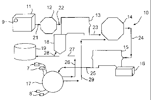
Fig. 1 is a schematic view of a system according to the present
invention.
Fig. 2 is a schematic view of a system according to the present
invention.
DESCRIPTION OF EMBODIMENTS PREFERRED
AT THE TIME OF FILING FOR THIS PATENT
As shown in Fig. 1, a system 10 according to the present invention has a
mud tank 11 that contains drilling mud which is a mixture of at least liquid
drilling fluid and barite material. Any known mixers or mixing system 9 may
be used in the tank 11 to maintain the homogeneity of the tank's contents.
The barite is present as a liquid slurry (e.g. pieces with a largest dimension
of
192 microns or less). This mud is fed (e.g. pumped by a pump) from the tank
11 via a flow line 21 to a barite recovery enhancement treatment apparatus
12. Within the apparatus 12, fluid may be heated (e.g. but not limited to,
from
ambient temperature to 300° F. or more); air bubbles may be
introduced to lower fluid viscosity; recovered fluid may be added to reduce
viscosity; fluid may be sheared; and/or treated ultrasonically.
CA 02260714 2006-03-28
-8a-
The treated fluid is then fed via a flow line 22 to a barite recovery
centrifuge 13 (e.g. like a commercially available Model 414TM from Alfa Laval
Company). In one aspect, a dual back-drive centrifuge (such as the Model 414)
is used. In the centrifuge 13 barite solids are separated from the fluid and
flow
into a barite recovery tank 18. In certain aspects about 50% up to 99% by
weight of the barite is taken from the fluid.
The fluid then flows from the centrifuge 13 via a flow line 23 to solids
removal treatment apparatus 14 (such as a Model S12-60-50TM commercially
available from Gordon Piaff Company). In the apparatus 14 the fluid may be
heated (e.g., but not limited to, up to 3000 F. or more); and additional fluid
(up to about 50%) (e.g., but not limited to, fluid recovered by the system 10)
may be added to reduce viscosity. Other treatments possible in apparatus 14
include shearing, heating, mixing, heat exchange and/or ultrasonic treatment.
The fluid is then fed via a line 24 to a decanting centrifuge 15 such as
Model 3400TM commercially available from Sharpies Company, which in one
aspect, is a dual back-drive centrifuge. The centrifuge 15 removes undesirable
solids such as silt, sand, barite, and formation fines from the fluid entering
the
centrifuge. In one aspect, these solids flow to a collection container such as
a
solids waste box 16. Alternatively, they can be hauled off for disposal.
The decanted fluid then flows from the centrifuge 15 to a
liquid/liquid separator 17 for separating very small solid particles from the
fluid
and/or for separating oil/brine liquid from undesirable liquid. A
commercially available "ultra high G" "nozzle jet" centrifuge such as
Model 24 HBTM commercially available from Dorr Oliver Company may
be used for the separator 17. In one aspect the
CA 02260714 1999-02-04
_g_
nozzle jet centrifuge separates undesirable solid particles (e.g. particles
with a
largest dimension of about 75 microns) from the fluid. Typical pumps 8 and
tanks 7 may be used with the separator 17, e.g. such as those used with an
ultra
high G nozzle jet centrifuge. A stream with undesirable solids flows in line
29 to
the apparatus 14 or it could, alternatively, be fed directly to the centrifuge
15.
Fluid processed by the separator 17 flows in line 27 to a recovery tank 19.
Typically this purified fluid is oil and/or this fluid includes additives,
brines, and
minimal solids. Preferably, this fluid is in condition for re-use in wellbore
operations; or, with additional treatment to produce a usable drilling fluid
in
condition for re-use.
In one aspect, the system 10 is used to recover barite from drilling fluid.
The fluid removed from the tank 11 is tested e.g. retort, particle size
analysis,
and density testing, to determine recovery ratio and equipment settings. Such
testing indicated treatments) to be applied in the treatment apparatus 12.
Fluid
flowing in the line 23 from the centrifuge 13 is also similarly tested. Such
testing
can indicate the nature of and settings for the apparatus 14, e.g.
temperature,
solids load, and optimum operating parameters for it, such as viscosity and
ratio
settings. The fluid flowing from the centrifuge 15 enters tile separator 17.
With
appropriate nozzle and disk selection for an ultra high G nozzle jet
centrifuge as
the separator 17, fusion of fine clays and other submicron solid particles in
the
fluid is enhanced, producing manageable larger particles. Underflow fluid
containing e.g. increased size or concentration solids is fed back to the
apparatus 14 for re-treatment. Overflow fluid containing less solids is fed to
the
tank 19. A portion of the overflow fluid (e.g. 1 % to 99%) may be fed in the
line
28 to the tank 18 (e.g. to blend a heavy weight fluid for re-use in lighter
weight
system, e.g. 19.5 parts per gallon blended with 6.7 parts per gallon).
A system 50 as shown in Fig. 2 is directed to removing brine from a
drilling fluid. Drilling fluid containing brine is maintained homogeneously in
a
tank 51 (which may have a system 9 as in Fig. 1). The solids removal treatment
apparatus 54 is like the apparatus 14 of Fig. 1. The centrifuge 55 is like
tile
centrifuge 15 of Fig. 1. The separator 57 is like the separator 17 of Fig. 1,
but
CA 02260714 2006-03-28
-10-
may be modified to deal with heavy liquids, e.g. using a booster pump,
impeller, and resized nozzle.
Purified fluid from the separator 57 is fed via a flow line 65 to filtration
apparatus 58 in which very fine particles (e.g. with a largest dimension of 10
microns or less) are removed. In one aspect the filtration apparatus 58 is a
filter press Model JWI 1200N-25-110-108-SYHS TM commercially available from
JWI Company. In one aspect Perlite or diatomaceous earth are fed to the
system.
Recovered fluid flows from the filtration apparatus 58 to a tank 59.
Preferably, such fluid is ready for re-use. Alternatively, such fluid may be
treated further, e.g. thermally or by surface filtration, reverse osmosis
and/or
chemical breakdown. Such fluid is then suitable for re-cycling and re-use.
Concentrated solids and/or polymers flow in line 64 from the centrifuge
57 to the apparatus 54, or alternatively, centrifuge 55.
The present invention, therefore, in certain aspects, discloses a method
for recovering a component from a wellbore fluid mixture that includes feeding
a wellbore fluid mixture to a decanting centrifuge, the wellbore fluid
containing
at least one liquid component and undesirable solids, separating undesirable
solids from the wellbore fluid mixture with the decanting centrifuge,
producing
an intermediate fluid containing the at least one liquid component and a
reduced amount of the undesirable solids, and feeding the intermediate fluid
to
a secondary centrifuge, producing a final fluid containing the at least one
liquid
component and a further reduced amount of the undesirable solids; such a
method wherein at least some of the undesirable solids are barite pieces,
wherein the barite pieces have a largest dimension of no more than 192
microns, wherein at least 50% of the barite pieces by weight are removed,
and/or wherein at least 99% of the barite pieces by weight are removed; any
such method wherein separated undesirable solids have a largest dimension of
at least 75 microns; any such method wherein the wellbore fluid is drilling
mud; any such method wherein the at least one liquid component of the
wellbore fluid includes brine; any such method further comprising filtering
the
final fluid to purify brine therein; any such method including removing
particles
with a largest dimension of no more than 10 microns from the final fluid; any
such method wherein the final fluid is reusable as a wellbore fluid.
The present invention, in certain aspects, discloses a method for
CA 02260714 1999-02-04
-11-
of no more than 10 microns from the final fluid; any such method wherein tile
final fluid is reusable as a wellbore fluid.
The present invention, in certain aspects, discloses a method for
recovering a component from a wellbore fluid mixture, the method including
feeding a wellbore fluid mixture to a decanting centrifuge, the wellbore fluid
containing at least one liquid component, barite pieces, and undesirable
solids,
separating undesirable solids from tile wellbore fluid mixture with tile
decanting
centrifuge, producing an intermediate fluid containing the at least one liquid
component and a reduced amount of the undesirable solids, feeding the
intermediate fluid to a secondary centrifuge, producing a final fluid
containing the
at least one liquid component and a further reduced amount of the undesirable
solids, wherein the barite piece's have a largest dimension of no more than
192
microns, and at least 99% of the barite pieces by weight are removed from the
wellbore fluid.
The present invention, in certain aspects, discloses a method for
recovering a component from a wellbore fluid mixture, the method including
mixing the wellbore fluid in a tank to maintain homogeneity, feeding a
wellbore
fluid mixture to a decanting centrifuge, the wellbore fluid containing at
least, one
liquid component and undesirable solids, separating undesirable solids from
the
wellbore fluid mixture with the decanting centrifuge, producing an
intermediate
fluid containing the at least one liquid component and a reduced amount of the
undesirable solids, feeding the intermediate fluid to a secondary centrifuge,
producing a final fluid containing the at least one liquid component and a
further
reduced amount of the undesirable solids, the at least one liquid component of
the wellbore fluid includes brine, and filtering the final fluid to purify the
brine, the
final fluid then reusable as a wellbore fluid.
Appended hereto and incorporated here for all purposes is the application
entitled "Wastewater Treatment Systems" co-owned with the present invention
and filed on even date herewith.
In conclusion, therefore, it is seen that the present invention and the
embodiments disclosed herein and those covered by the appended claims are
well adapted to carry out the objectives and obtain the ends set forth.
Certain
CA 02260714 2006-03-28
-11-
recovering a component from a wellbore fluid mixture, the method including
feeding a wellbore fluid mixture to a decanting centrifuge, the wellbore fluid
containing at least one liquid component, barite pieces, and undesirable
solids,
separating undesirable solids from the wellbore fluid mixture with the
decanting centrifuge, producing an intermediate fluid containing the at least
one liquid component and a reduced amount of the undesirable solids, feeding
the intermediate fluid to a secondary centrifuge, producing a final fluid
containing the at least one liquid component and a further reduced amount of
the undesirable solids, wherein the barite pieces have a largest dimension of
no more than 192 microns, and at least 99% of the barite pieces by weight are
removed from the wellbore fluid.
The present invention, in certain aspects, discloses a method for
recovering a component from a wellbore fluid mixture, the method including
mixing the wellbore fluid in a tank to maintain homogeneity, feeding a
wellbore
fluid mixture to a decanting centrifuge, the wellbore fluid containing at
least
one liquid component and undesirable solids, separating undesirable solids
from the wellbore fluid mixture with the decanting centrifuge, producing an
intermediate fluid containing the at least one liquid component and a reduced
amount of the undesirable solids, feeding the intermediate fluid to a
secondary
centrifuge, producing a final fluid containing the at least one liquid
component
and a further reduced amount of the undesirable solids, the at least one
liquid
component of the wellbore fluid includes brine, and filtering the final fluid
to
purify the brine, the final fluid then reusable as a wellbore fluid.
In conclusion, therefore, it is seen that the present invention and the
embodiments disclosed herein and those covered by the appended claims are
well adapted to carry out the objectives and obtain the ends set forth.
Certain
changes can be made in the subject matter without departing from the spirit
and the scope of this invention. It is realized that changes are possible
within
the scope of this invention and it is further intended that each element or
step
recited in any of the following claims is to be understood as referring to all
equivalent elements or steps. The following claims are intended to cover the
invention as broadly as legally possible in whatever form it may be utilized.