Note : Les descriptions sont présentées dans la langue officielle dans laquelle elles ont été soumises.
CA 02261789 1999-O1-25
WO 98/19181 PCT/US97/19355
METHOD AND SYSTEM FOR INCREASING FOLD TO STREAMER LENGTH
RATIO
BACKGROUND OF THE INVENTION
s This invention related to the field of marine seismic data acquisition and
more
particularly to the field of Common Mld-Point (a.k.a. "CMP") marine data
acquisition.
In the field of marine seismic data acquisition, seismic signal sources (e.g.
air guns)
are towed behind a vessel, which also tows a set of streamers. The streamers
include signal
receivers (e.g. hydrophones) which are sensitive to reflections, refractions,
and other
"information" from sound impulses emitted by the sources. In many modern
arrays,
multiple streamers and multiple sources are used, requiring very large pulling
forces to deal
with the drag associated with the towed arrays.
It has long been known that for high quality data, multiple traces of
information
from the same layer are required to be added. Since the noise associated in
each piece of
1 s information is random, the addition of multiple signals from the same sub-
surface reflection
point results in an increase in the information signal with a cancellation of
the noise. This
process is commonly known as the Common lVZd-Point method.
As is known in the art, the number of reflections from the same reflector is
commonly referred to as the "fold" of the survey. Increase in fold results in
an increase in
2 o signal-to-noise ratio, and, therefore, increase in fold is desirable.
Traditionally, to increase
fold, the number of hydrophones in the streamer is increased, making the
streamer longer.
It is also desirable to tow multiple streamers behind the seismic vessel with
the distance
between the steamers as small as possible, to increase resolution of the
survey.
Unfortunately, as streamer numbers incxease, so do the operational
constraints, resulting in
2 s an upper limit to the length of the streamer. Also, as the distance
between the steamers
decreases, the natural feathering or snaking movement of the streamer in the
water
increases the chances of the tangles in the ends of the streamers, especially
during turns.
Thus, the length of the streamer is again limited.
It has also been found that it is desirable to increase the long offset (i.e.,
the
s o distance between the source and the furthest receiver) in many surveys.
Such an increase
gives benefits that are well known in the art, (e.g. increase fold, better
define deep sub-salt
data, and generally improve signal-to-noise ratios). However, to increase the
offset, the
CA 02261789 1999-O1-25
WO 98/19181 PCT/US97/I9355
2
streamer must be lengthened. Increased streamer length increases the drag and
limits the
number of streamers that can be towed, which results in an increase in
streamer separation.
Further still, the signal strength of information received at long offsets is
significantly lower than that at the near offset. As the streamer length
increases, the signal
s strength decreases, resulting in the need for a larger source. However,
large sources
increase drag and deck handling problems, again limiting the size and/or
density of the
towable array.
Accordingly, there is a need for a method and system to increase the fold in a
marine survey, as well as the offset, without ( 1 ) increasing streamer
length, (2) decreasing
1 o the number of streamers, or (3) increasing the distance between the
streamers.
It is the object of the present invention to address the above-described
needs.
SUMMARY OF THE INVENTION
1 s According to the present invention, the above-described needs are
addressed by a
"seismic vessel" ("SEV"), which tows streamers and sources, used with a source
vessel
("SOV"). According to one embodiment, assuming that the length of the
streamers of the
SEV is L and that the separation between the source (on the SEV) and the head
of the
middle streamer is X, the source of SOV is positioned either L in front of the
source
2 o position of the SEV or L + X behind the last active streamer section of
the SEV. The
combined source-receiver offset coverage will be from X to X + 2L.
Further, the seismic source of the SOV will be fired with a delay relative to
the
source fire time of the SEV. The firing delay is optimized so that the seismic
information
generated by the source of the SEV is not influenced by the seismic
information generated
2 5 by the source of the SOV. Both shots are recorded into the same record.
The total record
length is kept as short as possible, but long enough so that the required
seismic inforn~ation
generated by the source of the SOV is included. By this, the cycle time
between shots is
minimized so that the maximum fold coverage is maintained.
For some deep water embodiments, the seismic recording is delayed relative to
the
3 o source fire time on the SEV, to reduce total cycle time and record sub-
surface data for a
longer period. The cycle time and fold is tuned for various water depths.
CA 02261789 2001-12-19
3
In some embodiments, the invention is used with single sources on the SEV,
while
in others, multiple sources are used. in still further embodiments, the SOV
deploys the
same number of sources as the SEV, and in other embodiments, differing numbers
of
sources between the SEV and the SOV are used. .
In still fwther embodiments, the source on the SOV has a different amplitude
(for
example, in an air gun array, either volume, .pressure, or both) than the
source of the SEV.
For alternative embodiments, the SOV source has the same amplitude as the SEV:
Still further, additional streamer vessels, deployed beside the SEV, are used
in other
embodiments.
In even further embodiments, more than one SOV is used. For example, the
position of SOV number J, in one embodiment, is either JL in front of the
source position
of the SEV or JL+X behind the last active streamer section an the SEV, The
combined
.a
source-receiver offset coverage will this be from X~ to X+(rL+L), The
different sources are
fired sequentially and recorded into the same record as described above.
In a first aspect, the invention provides a
. method for recording marine seismic data. in a data survey, the survey
having a survey
line, the method comprising:
towing a plurality of streamers behind a first vessel,
wherein the streamers comprise a set of seismic signal receivers positioned
along the
streamer for receiving seismic signals and Transmitting the signals to the
first vessel, and '
wherein the outermost streamers define a streamer path substantially parallel
to the survey
line; '
towing a first seismic signal source behind the first vessel,
wherein the receiver closest to the first seismic source defines a near offset
receiver,
where'm the distance between the near offset receiver and the first seismic
source defines
the near offset,
wherein the receiver furthest from the first seismic source defines a far
offset receiver,
and wherein the distance between the far offset receiver and the first seismic
source defines
the f rst vessel far offset;
CA 02261789 2001-12-19
3A
towing a second seismic signal source behind a second vessel wherein the
source behind the second
vessel is towed along the streamer path, wherein the distance between the
second source and .the
closest receiver is about L or less;
firing the one of the sources at a first instant, whereby a first source
firing event is defined; .
receiving, through the receivers in the streamers, information of the first
source firing event for a
time equal to the travel time from the one -of the sources to a maximum depth,
of interest to the far
offset receiver; .
firing the other of the sources at a second instant, whereby a second source
firing event is defined;
receiving, through the same receivers in the streamers, information of the
second source firing event
for a time equal to the travel time from the other of the sources to the
maximum depth of interest to
the far offset receiver; and
wherein the second source firing event occxirs before the end of the recording
of the information of
the first source firing event.
In a second aspect,, the invention provides a
method fox recording marine seismic data in a data survey, the survey having a
survey
line, the method comprising: .
towing a plurality of streamers behind a first vessel,
wherein the streamers comprise a set of seismic signal receivers positioned
along the
streamer for receiving seismic signals and transmitting the signals to the
first vessel, and
wherein the outermost streamers define a streamer path substantially parallel
to the survey
line;
towing a first seiSmiC Signal source behind the first vessel,
wherein the receiver closest to the first seismuc source defines a near offset
receiver,
wherein the distance between the near offset receiver and the first seismic
source defines
the near offset,
wherein the receiver. fiuthest from the first seismic source defines a far
offset receiver,
and wherein the distance between the far offset receiver and the first seismic
source defines
the first vessel far offset; .
CA 02261789 2001-12-19
3B
towing a second seismic signal source behind a second vessel wherein the
source behind the second
vessel is towed.along the streamer path, wherein the distance between the
second source and the
closest receiver is about the first vessel far offset, or less; -
firing the one of the sources at a f rst instant, whereby a first sowce fu ing
event is defined;
receiving, through the receivers in the streamers, information of the first
source f ring event for a
time equal to the travel time from the one of the sources to a maximum depth
of interest to the far
offset receiver;
f ring the other of the sources at a second instant, whereby a second source
firing event is defined;
receiving, through the same receivers in the streamers, information of the
second source firing event
for a time equal to the travel time from the other of the sources to the
maximum depth of interest to
the far offset receiver; and
wherein the second source firing event occurs before the end of the recording
of the information of
the first source firing event.
In summary, through use of the present invention, seismic offset is increased
without increasing streamer length, thus reducing the in water equipment, and,
at the same
time, high fold coverage is maintained and enhanced. ~ .
CA 02261789 1999-O1-25
WO 98/19181 PCT/US97/19355
4
DESCRIPTION OF THE DRAWINGS
For a more complete understanding of the present invention and for further
advantages thereof, reference is made to the following Detailed Description
taken in
s conjunction with the accompanying drawings, in which:
Fig. 1 is a side view showing receiver and source locations in relation to
reflectors.
Fig. 2 is a representational graph showing the order of recording of
information from the
reflectors.
Fig. 3 is a top view of an embodiment of the invention.
z o Fig. 4 is a top view of an altennative embodiment of the invention.
Fig. 5 is a timing diagram of a method of firing sources according to an
embodiment of the
invention.
Figs 6A, 6B, and 6C are top views of alternative embodiments of the invention.
It is to be noted, however, that the appended drawings illustrate only typical
embodiments
1 s of this invention and are therefore not to be considered limiting of its
scope, for the invention may
admit to other equally effective embodiments.
DETAILED DESCRIPTION
Referring now to Fig. 3, an example embodiment of the invention is shown of a
system for
2 o seismic data acquisition along a survey line 1 comprising: a first vessel
12a towing hydrophone
streamers 10 having hydrophones 14 housed therein, including a near hydrophone
14n and a far
hydrophone 14f. Vessel 12a also tows a first seismic source 16a. The distance
between the first
seismic source 16a and the near hydrophone 14n defines the near offset N.O.,
and the distance
between the first seismic source 16a and the far hydrophone 14f defines the
far offset F.O.
2s A second vessel 12b is also shown, towing a second seismic source 16b ahead
of the first
vessel 12a. The distance between the second source 16b and the near hydrophone
14n is about the
first vessel far offset F.O. or less.
Although the invention described herein is usefi~l in a single streamer
system, in preferred
embodiments, the system comprises multiple streamers IO (here three are shown,
although the
s o number is not limited by the present invention) being towed by the first
vessel 12a. Also, multiple
sources 16a are towed by the first vessel 12a and multiple sources 16b are
towed behind second
vessel 12b, according to still a fiuther embodiment.
CA 02261789 1999-O1-25
WO 98/19181 5 PCT/US97/19355
s Referring now to Fig. 4, a specific embodiment is shown with multiple source
elements l6al
and 16a2 making up the sowce behind vessel 12a and sowce elements 16b1 and
16b2 making up
the sowce behind vessel 12b. According to this embodiment, the sowce elements
16a1 and 16x2
are e.g. spaced laterally about 50 meters, as are sowce elements 16b1 and
16b2. The steamers 10
are e.g. spaced about 100 meters from each other.
zo As the vessels 12a and 12b move along the survey line, source 16a1 fires,
and CMP hits
20a1 (representing infonrnation from reflectors beneath the surface, as
explained more fully below)
are recorded. Before the recording of CNiP hits 20x1 from the deepest depth of
interest ends
(which may take several seconds) sowce element l6bi fires, timed such that the
earliest information
of interest from the firing of sowce element 16b 1 (seen in Fig. 4 as CMP hits
20b 1 ) are recorded in
15 streamers 10 just after the last information of interest is recorded from
the firing of sowce element
16a1. Then, after recording of the deepest information of interest from the
firing of sowce element
16b2, sowce element 16x2 fires, CMP hits 20x2 are recorded, and before the CMP
hits from the
deepest information of interest are recorded, sowce element 16b2 fires. CMP
hits 20b2 are
recorded from the firing of sowce element 16b2, preferably into the same
record as the hits 20a2.
2 o Through careful timing of the firing of the various sowce elements, the
following is achieved: long
offset, high fold marine data, and dense streamer spacing. A practical
configuration would be to
use twelve streamers with length of about 4 km, a streamer separation of 100
meters, a distance
between source elements 16a (2 elements, with a spacing of about 50 meters)
and vessel 12a of
between about 200 and 350 meters, and a distance between the source elements
16a and the first
2s hydrophone in streamers 10 of between about 200 and 350 meters. Second
vessel 12b is seen
towing source elements 16b (2 elements, with a spacing of about 50 meters),
the distance between
the sowce elements 16a and 16b is about the length of the streamers (about 4
km).
According to another aspect of the invention, referring again to Fig. 3 a
method for
recording marine seismic data in a data survey is provided, comprising:
s o towing a plwality of streamers 10 behind a first vessel 12a, wherein the
streamers comprise
a set of seismic signal receivers 14 positioned along the streamers 10 for
receiving seismic signals
and transmitting the signals to the first vessel 12a, and wherein the
outermost streamers l0a and
lOc define a streamer path 15 substantially parallel to the survey line 1;
towing a first seismic signal sowce 16a behind the first vessel 12a, wherein
the receiver
3 s closest to the sowce 16a defines a near offset receiver 14n and the
distance between the near offset
CA 02261789 1999-O1-25
WO 98/19181 PCT/US97/19355
6
receiver 14n and the source 16a defines the near offset N.O., and wherein the
receiver furthest from
the source defines a far offset receiver 14f and the distance between the far
offset receiver 14f and
the source 16a defines the fast vessel far offset F.O.; and
towing a second seismic signal source 16b behind a second vessel 12b wherein
the source
16b behind the second vessel 12b is towed along the streamer path 15, wherein
the distance
~ o between the second source 16b and the near offset receiver 14n is
optimally the length of the
streamers 14.
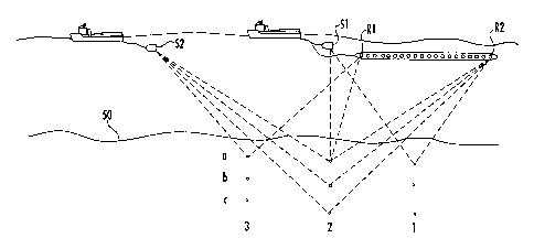
Referring now to Figs. 1, 2, and 5, the timing of a method useful with the
embodiment of
Fig. 3 will be described. Fig. 1 shows an idealized plot of sources S 1 and S2
and receivers Rl and
R2, and the rays from sources S1 and S2 to reflectors al-3, bl-3, and cl-3,
below the earth's
i s surface 50. For simplicity, not all rays are traced in Fig. 1. Fig. S
shows a timing diagram of the
firing of the sources S 1 and S2 and the infoirnation recorded at hydrophones
Rl and R2, and Fig 2
shows the recordings made from hydrophones Rl and R2, with identification of
the reflectors
represented in the recording.
Referring now to Fig. 5, according to this aspect of the invention, the method
comprises:
2 o firing source S 1 at a first instant t, whereby a first source firing
event is defined; recording at an
instant t+x, through the receivers 14 in the streamers 10, into a first record
{Rl of Fig. 2),
information from reflectors a2, b2, c2 to the first source filing event for a
time equal to the travel
time from sowce S 1 to a ma~cimum depth of interest. Likewise, information
from the reaction of
reflectors al, bl, and cl is recorded into the first record through receiver
R2. This time is
2 s represented as time tdmaxl in Fig. 5.
Next, the method fiuther comprises firing the other of the source S2 at a
second instant t+y
(Fig. 5), whereby a second source firing event is defined and wherein the
second source firing event
occurs before the end of the recording of the information of the first source
firing event. The result
is the recording of information from reflectors a3, b3, and c3 (into receiver
Rl ) a2, b2, and c2 (into
s o receiver R2), for a time tdmax equal to the travel time from the source S2
to the maximum depth of
interest and to the fiuthest receiver, R2. Referring now to Fig. 2, a record
of information signals
into the first receiver Rl is recorded for both the first source S 1 and the
second source S2, resulting
in the record Rl of Fig. 2, in which reflectors a2, b2, and c2 are recorded as
a result of source S 1,
and reflectors a3, b3, and c3 are recorded as a result of source S2.
Furthermore, referring to Fig. 2,
s s a record of information signals into the second receiver R2 is recorded
for both the first source S 1
CA 02261789 1999-O1-25
WO 98/19181 PCT/US97/19355
7
s and the second source S2, resulting in the record R2 of Fig. 2, in which
reflectors a 1, b 1, and c 1 are
recorded as a result of source S 1 and reflectors a2, b2, and c2 are recorded
as a result of source S2.
Recording the information resulting from the firing of the second source into
the same
record as the record resulting from firing the first source provides
efficiencies of timing and
computational power. However, in alternative embodiments, the information of
the second source
1 o is recorded on a separate record.
In the case that the results of different sources are recorded into the same
record, the data
need to be separated into information gathered from each source and processed
according to
traditional methods, for example as CMP gathers. Those of skill in the art
will recognize that as
the survey continues, there will be many sets of data from all reflectors to
be gathered, some
~s recorded from hydrophones between Rl and R2, and the invention is not
limited to the example
shown.
Referring now to Figs. 6A-6C, various alternative embodiments are shown. As
seen in Fig.
6A, the simple tow boat embodiment is shown wherein the length of the
streamers is L, and the
separation between source S 1 of vessel 12a and the head of the middle
streamer is X, source S2 is
2 o positioned L in front of source S 1, or, as seen in Fig. 6C, L+X behind
the last active streamer.
Referring now to Fig. 6B, according to an alternative embodiment, a third
source 16c is towed
behind a third source vessel 12c, also along the streamer path, wherein the
distance between the
third source 16c and the far offset receiver is about 2L+X. The third source
16c is fired at a third
instant, whereby a third source firing event is defined, and the information
from the third source
2 s firing event is recorded, through the receivers 14 in the streamers 10,
preferably into the same
record as the information from the firing of sources S 1 and S2 for a time
equal to the travel time
from the third source to the maximum depth of interest and to the far offset
receiver.
The above-described embodiments are given by way of example only. Other
embodiments
will occur to those of skill in the art which will not depart from the spirit
of the invention.