Sélection de la langue

Search

Sommaire du brevet 2262559 

Énoncé de désistement de responsabilité concernant l'information provenant de tiers

Une partie des informations de ce site Web a été fournie par des sources externes. Le gouvernement du Canada n'assume aucune responsabilité concernant la précision, l'actualité ou la fiabilité des informations fournies par les sources externes. Les utilisateurs qui désirent employer cette information devraient consulter directement la source des informations. Le contenu fourni par les sources externes n'est pas assujetti aux exigences sur les langues officielles, la protection des renseignements personnels et l'accessibilité.

Disponibilité de l'Abrégé et des Revendications

L'apparition de différences dans le texte et l'image des Revendications et de l'Abrégé dépend du moment auquel le document est publié. Les textes des Revendications et de l'Abrégé sont affichés :

  • lorsque la demande peut être examinée par le public;
  • lorsque le brevet est émis (délivrance).
(12) Brevet: (11) CA 2262559
(54) Titre français: RADEAU DE SAUVETAGE
(54) Titre anglais: LIFERAFT
Statut: Périmé et au-delà du délai pour l’annulation
Données bibliographiques
(51) Classification internationale des brevets (CIB):
  • B63C 09/04 (2006.01)
  • B63C 09/06 (2006.01)
(72) Inventeurs :
  • MARTIN, MICHAEL (Royaume-Uni)
(73) Titulaires :
  • SURVITEC GROUP LIMITED
(71) Demandeurs :
  • SURVITEC GROUP LIMITED (Royaume-Uni)
(74) Agent: BERESKIN & PARR LLP/S.E.N.C.R.L.,S.R.L.
(74) Co-agent:
(45) Délivré: 2002-08-13
(86) Date de dépôt PCT: 1998-06-04
(87) Mise à la disponibilité du public: 1998-12-10
Requête d'examen: 1999-07-06
Licence disponible: S.O.
Cédé au domaine public: S.O.
(25) Langue des documents déposés: Anglais

Traité de coopération en matière de brevets (PCT): Oui
(86) Numéro de la demande PCT: PCT/GB1998/001642
(87) Numéro de publication internationale PCT: GB1998001642
(85) Entrée nationale: 1999-01-29

(30) Données de priorité de la demande:
Numéro de la demande Pays / territoire Date
9711531.5 (Royaume-Uni) 1997-06-05

Abrégés

Abrégé français

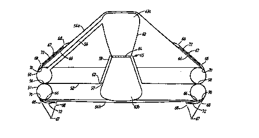
Radeau de sauvetage possédant une base (52) entourée par un ou plusieurs tubes gonflables (50, 51). Ce radeau comporte deux auvents (54a, 54b), l'un (54a) recouvrant un côté de la base (52) et l'autre (54b) recouvrant l'autre côté de la base (52). Quand le radeau de sauvetage est déployé sur l'eau, des moyens de support, pouvant être constitués par une colonne gonflable (63), dressent l'auvent afin qu'il soit au-dessus de l'eau. L'autre auvent (54b) n'est pas dressé et repose dans l'eau. Un système de poids (67) et de cordes élastiques (66) font de l'auvent reposant dans l'eau un dispositif de stabilisation sous forme de poches d'eau. L'auvent déployé (54a) possède des moyens semblables mais, quand cet auvent (54a) est dressé, ces moyens sont alignés sur la surface de l'auvent et ne jouent, par conséquent, aucun rôle dans l'opération du radeau de sauvetage.


Abrégé anglais


A liferaft has a floor (52) surrounded by one or more inflatable tubes (50,
51). Two canopies (54a, 54b) are provided, one (54a) covering one side of the
floor (52) and the other (54b) covering the other side of the floor (52). When
the liferaft is deployed on water, support means, which may be an inflatable
column (63), erect the canopy (54a) that is above the water. The other canopy
(54b) is unerected and lies in the water. The system of weights (67) and
elastic ropes (66) forms the canopy in the water into stabilizing means in the
form of water pockets. Similar means are provided on the deployed canopy (54a)
but, when the canopy (54a) is erected, they lie flush with the canopy surface
and so do not interfere with the operation of the liferaft.

Revendications

Note : Les revendications sont présentées dans la langue officielle dans laquelle elles ont été soumises.


CLAIMS
1. A reversible liferaft comprising a floor (52) having a
periphery, a first side and a second side, at least one
inflatable tube (50,51) surrounding and connected to the
periphery of the sheet, an erectable first canopy (54a)
extending over the first side of the floor (52) and an
erectable second canopy (54b) extending over the second side
of the floor (52), support means (63) for holding erect that
one of the first and second canopies (54a,54b) which is on the
upper side of the liferaft when the liferaft is deployed and
floating on water, the other of the first and second canopies
(54a,54b) then being unerected, and shaping means (66,67)
operative when the liferaft is deployed and floating on water
for providing stabilizing means for the liferaft from said
other canopy (54a,54b).
2. A liferaft according to claim 1 wherein the shaping means
(66,67) form said other canopy into a stabilizing device
projecting downwardly from the side of the liferaft that is
the lower side when the liferaft is deployed and floating on
water.
3. A liferaft according to claim 2 wherein the stabilizing
device comprises a water pocket.

11
4. A liferaft according to claim 3 wherein the water pocket
is of triangular cross-section.
5. A liferaft according to claim 2 or claim 3 wherein the
water pocket is annular extending around the whole lower side
of the liferaft.
6. A liferaft according to any one of claims 3 to 5 wherein
the water pocket is sub-divided into sections.
7. A liferaft according to any one of claims 3 to 6 wherein
the shaping means (66,67) form the water pocket from a
V-shaped fold of the canopy, the fold being provided with holes
(68) for the passage therethrough of water.
8. A liferaft according to claim 7 wherein the shaping means
comprise an elastic rope (66), each of the first and second
canopies (54a,54b) carrying at least one elastic rope (66),
each elastic rope (66) being tensioned when the associated
canopy (54a,54b) is erect and forming the V-shaped fold when
the associated canopy (54a,54b) is unerected.
9. A liferaft according to claim 8 wherein plurality of
elastic ropes (66) are provided on each of the first and
second canopies, the ropes (66) associated with each canopy

12
(54a,54b) being arranged at spaced locations around the
associated canopy (54a,54b), the ropes (66) extending
side-by-side.
10. A liferaft according to any one of claims 7 to 9 wherein
the shaping means comprise a weight (67), each of the first
and second canopies carrying at least one weight, each weight
(67) forming the V-shaped fold when the associated canopy
(54a,54b) is unerected and the liferaft is deployed and
floating on water.
11. A liferaft according to claim 10 wherein a plurality of
weights (67) are provided on each of the first and second
canopies (54a,54b).
12. A liferaft according to claim 10 or claim 11 when
dependent on claim 8 wherein each weight (67) is associated
with a respective rope (66).
13. A liferaft according to any one of claims 8 to 12 wherein
a sheet (72) is provided extending between upper ends of the
V-shaped fold to close said upper end and so prevent water
passing from the water pocket to the interior of the
associated canopy (54a,54b).

Description

Note : Les descriptions sont présentées dans la langue officielle dans laquelle elles ont été soumises.


CA 02262~9 1999-01-29
W098155358 PCT/GB98101~2
TIF~RAT~T
This invention relates to a liferaft and in particular to a
reversible liferaft i.e. one which can be occupied
satisfactorily regardless of the way it floats.
It is known to provide a liferaft with means which project
into the water, when the liferaft is floating on water, and
stabilize the liferaft. One example is the provision of
stabilizing pockets which project downwards into the water and
fill with water to provide a degree of stability when the
inflated liferaft is floating on water. However, these
pockets do require the usage of a significant amount of fabric
and when not in use can cause obstruction. When such pockets
are provided on both the upper and lower sides of a reversible
liferaft, those pockets which are on the upper side can whip
or flutter in windy conditions.
It is the object of the present invention to provide a
liferaft in which the above disadvantages are substantially
overcome.
According to the invention, there is provided a reversible
liferaft comprising a floor having a periphery, a first side
and a second side, at least one inflatable tube surrounding

CA 02262~9 1999-01-29
W098/55358 PCT/GB98/01642
2 -
~
and connected to the periphery of the sheet, an erectablefirst canopy extending over the first side of the floor and an
erectable second canopy extending over the second side of the
floor, support means for holding erect that one of the first
and second canopies which is on the upper side of the liferaft
when the liferaft is deployed and floating on water, the other
of the first and second canopies then being unerected, and
shaping means operative when the liferaft is deployed and
floating on water for providing stabilizing means for the
liferaft from said other canopy.
One embodiment of the invention, a reversible liferaft capable
of carrying several people, will now be described by way of
example only with reference to the accompanying drawing in
which:-
Figure 1 shows a perspective view from above of an inflatedreversible liferaft,
Figure 2 shows a vertical cross-section through the liferaft
shown in Figure l;
Figure 3 shows on an enlarged scale part of the liferaft shown
in Figure 2; and

CA 02262~9 1999-01-29
W098t55358 PCT/GB98/01642
Figure 4 shows on an enlarged scale another part of the
liferaft shown in Figure 2.
Referring first to Figure 1, the liferaft comprises two
buoyancy tubes 50,51 which, when inflated, are toroidal. Both
tubes 50,51 are ~anufactured from air-holding waterproof
fabric. They are positioned, when inflated, one above the
other. The tubes 51,52 are joined together along a circular
line 58 of contact (see Figure 2). The buoyancy tubes 51,52
may alternatively be polygonal comprising for example eight,
ten or twelve straight sections with angled corners between
them. There may, of course, be more or less than two tubes
51,52.
A sheet 52 of waterproof fabric is joined e.g. by adhesive or
welding, to the tubes 50,51 at the line 58 of contact to
provide a floor for the liferaft.
A circular aperture 57 is formed at the centre of the sheet
52. A part conical sleeve 59 has a wider circular end 62
attached to the periphery of the aperture 57. The other,
narrower, end 64 of the sleeve 59 is attached to the centre 65
of an inflatable column 63 which, when inflated, is of
circular cross-section. The column 63 is in the form of two
part cones, as can be seen in Figure 2. The narrow ends of

CA 02262~9 1999-01-29
W098l55358 PCT/GB98/0l642
the part cones are at the centre 65 of the column 63 and the
wider ends 63a and 63b are at the top and bottom of the column
63 respectively.
Two canopies 54a and 54b are provided, each comprising a sheet
of waterproof fabric. One canopy 54a overlies a first side of
the floor 52 and the other canopy overlies a second side of
the floor 52. Each canopy 54a,54b is part conical when
deployed with a wider end connected around an associated one
of the tubes 51,52 along a line 70 and a narrower end closed
by a panel 61. Each canopy 54a,54b carries a plurality of
weights 67 located at angularly spaced intervals around the
associated canopy 54a,54b and a plurality of elasticated ropes
66 (sometimes known as "bungee cords~'). The elasticated ropes
66 extend side-by-side along the length of the associated
canopy 54a,54b and are equi-angularly spaced around the
associated canopy 54a,54b. (Only some weights 67 and ropes 66
are shown in Figure 1.)
As best seen in ~igure 3, each elasticated rope 66 is
connected at one end to a first attachment point 69a adjacent
the associated tube 50,51 and a second attachment point 69b
spaced along the associated canopy 54a,54b. The ropes 66 and
the attachment points 69a,69b are within the associated canopy
54a,54b, as seen in Figure 3. When the associated canopy

CA 02262~9 1999-01-29
W098/55358 PCT/GB98/01~2
54a,54b is deployed (as is the upper canopy 54a in the
Figures) the ropes 66 are tensioned.
Each weight 67 is attached to the associated canopy 54a,54b
and is at a position approximately level with the midpoint of
the length of an associated elasticated rope 66. (Although
the weights 67 appear in Figures 2, 3 and 4 to be in the same
plane as the elasticated ropes 66, they do not have to be so
positioned and may be positioned as shown in Figure l).
Several holes 68 are provided in each canopy 54a,54b. Some
holes 68 are positioned closer to the associated tube 50 or 51
than the weights 67 and others are positioned further from the
associated tube 50 or 51 than the weights 67.
Two secondary skins 72 are provided of the same fabric as the
canopies 54a,54b. Each secondary skin 72 lies between a
respective canopy 54a and 54b and the elasticated ropes 66.
As seen particularly in Figure 2, when the liferaft is
inflated and floating on water. The column 63 is forced
upwards due to buoyancy forces and takes up the elevated
position shown. The extent of this elevation is limited by
the constraint applied by the sleeve 59 and the upper canopy
54a. Thus, one canopy 54a extends from the upper buoyancy
tube 50 and over the top end 63a of the column 63 and is thus

CA 02262~9 1999-01-29
W098/5~58 PCTIGB98/01642
deployed for use. The other canopy 54b is positioned under
the liferaft, extending from the lower tube 51 and under the
lower end 63b of the column 63. This canopy 54b is not
deployed by the column 63. As can be seen particularly in
Figure 3, the elasticated ropes 66 associated with the upper
canopy 54a are stretched by the effect of the column on the
canopy 54a.
The lower end 63b of the column 63 does not act on the lower
canopy 54b and so the elasticated ropes 66 associated with the
lower canopy 54b relax i.e. shorten, and pull on the material
of the canopy at the connections 69a,69b. The part of the
canopy 54b overlying the elasticated ropes 66 projects
downwards in a fold, due to the force applied by the weights
67, and is shaped by the weights 67 and the ropes 66 to have
a substantially V-shaped triangular cross-section, as seen in
Figures 2 and 4. The holes 68 in the lower canopy 54b allow
water to enter into and air to exit from the generally
triangular cross-section annular water pocket so formed. The
presence of the secondary skin 72 prevents water entering the
interior of the lower canopy 54b and so, should the liferaft
invert, the space formed by this canopy 54b when deployed by
the column 63 will be dry. This secondary skin 72 on the
underside of the liferaft forms into folds under the action of
the ropes 66. A plurality of fabric bulkheads (not shown) may

CA 02262~9 l999-0l-29
W098/5S358 PCT/GB98/01642
be provided to divide the space into a plurality of
circumferentially separate pockets. The overall effect is
that the liferaft is provided with stability.
The remainder of the lower canopy 54b is held taut against the
underside of the liferaft, as seen in Figure 2.
As shown in Figure 2, the column 63 is connected via a
flexible feed tube 56 to the upper buoyancy tube 50. The
column 63 and buoyancy tube 50 are thus both automatically
inflated from the same source (not shown), when the liferaft
is deployed in water, a valve system (not shown) ensuring that
the tubes 50 and 51 are inflated before the column 63.
Each canopy 54a and 54b is provided with entrances 74 through
which an occupant can climb from the water over the buoyancy
tubes 50, 51 and into the liferaft. Observation ports or
windows (not shown) may also be provided.
Although in the embodiment just descrlbed the upper canopy is
supported in the erected condition by means of a single column
63, other support means such as arching inflatable tubes or
rigid steel tubes may alternatively be utilized.

CA 02262~9 1999-01-29
W098/~5358 pcTlGs98lol~2 -
When the liferaft is deployed (as shown in the drawings) the
outer surface of the upper canopy 54a remains substantially
smooth. The pockets which would be formed if the upper canopy
were on the underside effectively retract thus preventing
fluttering, or in the extreme, whipping, due to wind. Further
no obstruction is caused and there are no places where
unwanted water due to rain or wave action can collect. The
overall construction provides for economical use of fabric.
In the embodiment described above with reference to the
drawings, the water pocket extends around the whole of the
undersurface of the liferaft. This need not be the case. By
providing ropes 66 and weights 67 on only portions of the
canopy 54b, a succession of angularly spaced water pockets may
be provided. Of course, only one water pocket may be formed
of limited circumferential extent.
Further, although the embodiment described above forms water
pockets, other stabilizing means may be deployed. For
example, vertical boards may be deployed or other stabilizing
devices.
The weights 67 are optional. The canopy 54b may fold under
its own weight. The elastic ropes 66 may be replaced by

CA 02262559 1999-01-29
W098/55358 PCT/GB98/01642
springs or any other extensible device that can relax and
deploy a stabilizing device.

Dessin représentatif
Une figure unique qui représente un dessin illustrant l'invention.
États administratifs

2024-08-01 : Dans le cadre de la transition vers les Brevets de nouvelle génération (BNG), la base de données sur les brevets canadiens (BDBC) contient désormais un Historique d'événement plus détaillé, qui reproduit le Journal des événements de notre nouvelle solution interne.

Veuillez noter que les événements débutant par « Inactive : » se réfèrent à des événements qui ne sont plus utilisés dans notre nouvelle solution interne.

Pour une meilleure compréhension de l'état de la demande ou brevet qui figure sur cette page, la rubrique Mise en garde , et les descriptions de Brevet , Historique d'événement , Taxes périodiques et Historique des paiements devraient être consultées.

Historique d'événement

Description Date
Le délai pour l'annulation est expiré 2005-06-06
Lettre envoyée 2004-06-04
Lettre envoyée 2003-06-26
Accordé par délivrance 2002-08-13
Inactive : Page couverture publiée 2002-08-12
Inactive : Taxe finale reçue 2002-06-03
Préoctroi 2002-06-03
Un avis d'acceptation est envoyé 2002-04-15
Lettre envoyée 2002-04-15
Un avis d'acceptation est envoyé 2002-04-15
Inactive : Approuvée aux fins d'acceptation (AFA) 2002-03-27
Lettre envoyée 1999-07-26
Requête d'examen reçue 1999-07-06
Exigences pour une requête d'examen - jugée conforme 1999-07-06
Toutes les exigences pour l'examen - jugée conforme 1999-07-06
Inactive : CIB attribuée 1999-04-06
Symbole de classement modifié 1999-04-06
Inactive : CIB attribuée 1999-04-06
Inactive : CIB en 1re position 1999-04-06
Inactive : Notice - Entrée phase nat. - Pas de RE 1999-03-23
Demande reçue - PCT 1999-03-19
Demande publiée (accessible au public) 1998-12-10

Historique d'abandonnement

Il n'y a pas d'historique d'abandonnement

Taxes périodiques

Le dernier paiement a été reçu le 2002-05-16

Avis : Si le paiement en totalité n'a pas été reçu au plus tard à la date indiquée, une taxe supplémentaire peut être imposée, soit une des taxes suivantes :

  • taxe de rétablissement ;
  • taxe pour paiement en souffrance ; ou
  • taxe additionnelle pour le renversement d'une péremption réputée.

Les taxes sur les brevets sont ajustées au 1er janvier de chaque année. Les montants ci-dessus sont les montants actuels s'ils sont reçus au plus tard le 31 décembre de l'année en cours.
Veuillez vous référer à la page web des taxes sur les brevets de l'OPIC pour voir tous les montants actuels des taxes.

Historique des taxes

Type de taxes Anniversaire Échéance Date payée
Taxe nationale de base - générale 1999-01-29
Enregistrement d'un document 1999-01-29
Requête d'examen - générale 1999-07-06
TM (demande, 2e anniv.) - générale 02 2000-06-05 2000-05-26
TM (demande, 3e anniv.) - générale 03 2001-06-04 2001-05-17
TM (demande, 4e anniv.) - générale 04 2002-06-04 2002-05-16
Taxe finale - générale 2002-06-03
Enregistrement d'un document 2003-05-13
TM (brevet, 5e anniv.) - générale 2003-06-04 2003-05-20
Titulaires au dossier

Les titulaires actuels et antérieures au dossier sont affichés en ordre alphabétique.

Titulaires actuels au dossier
SURVITEC GROUP LIMITED
Titulaires antérieures au dossier
MICHAEL MARTIN
Les propriétaires antérieurs qui ne figurent pas dans la liste des « Propriétaires au dossier » apparaîtront dans d'autres documents au dossier.
Documents

Pour visionner les fichiers sélectionnés, entrer le code reCAPTCHA :


Pour visualiser une image, cliquer sur un lien dans la colonne description du document (Temporairement non-disponible). Pour télécharger l'image (les images), cliquer l'une ou plusieurs cases à cocher dans la première colonne et ensuite cliquer sur le bouton "Télécharger sélection en format PDF (archive Zip)" ou le bouton "Télécharger sélection (en un fichier PDF fusionné)".

Liste des documents de brevet publiés et non publiés sur la BDBC .

Si vous avez des difficultés à accéder au contenu, veuillez communiquer avec le Centre de services à la clientèle au 1-866-997-1936, ou envoyer un courriel au Centre de service à la clientèle de l'OPIC.

({010=Tous les documents, 020=Au moment du dépôt, 030=Au moment de la mise à la disponibilité du public, 040=À la délivrance, 050=Examen, 060=Correspondance reçue, 070=Divers, 080=Correspondance envoyée, 090=Paiement})


Description du
Document 
Date
(aaaa-mm-jj) 
Nombre de pages   Taille de l'image (Ko) 
Abrégé 1999-01-28 1 51
Description 1999-01-28 9 267
Revendications 1999-01-28 3 91
Dessins 1999-01-28 4 78
Dessin représentatif 1999-04-15 1 9
Avis d'entree dans la phase nationale 1999-03-22 1 193
Courtoisie - Certificat d'enregistrement (document(s) connexe(s)) 1999-03-22 1 117
Accusé de réception de la requête d'examen 1999-07-25 1 193
Rappel de taxe de maintien due 2000-02-06 1 113
Avis du commissaire - Demande jugée acceptable 2002-04-14 1 166
Courtoisie - Certificat d'enregistrement (document(s) connexe(s)) 2003-06-25 1 105
Avis concernant la taxe de maintien 2004-08-01 1 172
PCT 1999-01-28 4 133
Correspondance 2002-06-02 1 32