Sélection de la langue

Search

Sommaire du brevet 2263255 

Énoncé de désistement de responsabilité concernant l'information provenant de tiers

Une partie des informations de ce site Web a été fournie par des sources externes. Le gouvernement du Canada n'assume aucune responsabilité concernant la précision, l'actualité ou la fiabilité des informations fournies par les sources externes. Les utilisateurs qui désirent employer cette information devraient consulter directement la source des informations. Le contenu fourni par les sources externes n'est pas assujetti aux exigences sur les langues officielles, la protection des renseignements personnels et l'accessibilité.

Disponibilité de l'Abrégé et des Revendications

L'apparition de différences dans le texte et l'image des Revendications et de l'Abrégé dépend du moment auquel le document est publié. Les textes des Revendications et de l'Abrégé sont affichés :

  • lorsque la demande peut être examinée par le public;
  • lorsque le brevet est émis (délivrance).
(12) Brevet: (11) CA 2263255
(54) Titre français: PLATEAU CIRCULAIRE D'AUBES PLACE AUX EXTREMITES INTERNES ET RATTACHE AU STATOR PAR UNE BAGUE DE RACCORD
(54) Titre anglais: CIRCULAR STAGE OF VANES AT INTERNAL ENDS CONNECTED BY A CONNECTING RING
Statut: Durée expirée - au-delà du délai suivant l'octroi
Données bibliographiques
(51) Classification internationale des brevets (CIB):
  • F01D 07/00 (2006.01)
  • F01D 17/16 (2006.01)
(72) Inventeurs :
  • AGRAM, DANIEL ANDRE (France)
  • MARLIN, ANNE-CECILE CHRISTINE (France)
(73) Titulaires :
  • SNECMA
(71) Demandeurs :
  • SNECMA (France)
(74) Agent: LAVERY, DE BILLY, LLP
(74) Co-agent:
(45) Délivré: 2009-02-24
(22) Date de dépôt: 1999-03-01
(41) Mise à la disponibilité du public: 1999-09-05
Requête d'examen: 2004-01-16
Licence disponible: S.O.
Cédé au domaine public: S.O.
(25) Langue des documents déposés: Anglais

Traité de coopération en matière de brevets (PCT): Non

(30) Données de priorité de la demande:
Numéro de la demande Pays / territoire Date
98 02675 (France) 1998-03-05

Abrégés

Abrégé français

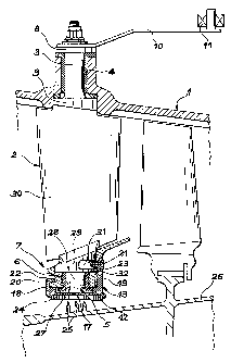
La présente invention a trait à un étage d'aubes de redresseurs lié à un stator et dont les extrémités intérieures sont soutenues par un anneau de liaison composé d'un anneau de support et d'un anneau de raidissage, dont une des lèvres s'étend à travers l'anneau de support et pénètre dans les entailles pratiquées dans les extrémités des aubes. Il s'ensuit que la possibilité que les aubes puissent se dégager accidentellement par suite d'un bris desdites aubes est éliminée.


Abrégé anglais

The present invention relates to a rectifier vane stage connected to a stator that is supported at the internal ends by a connecting ring which comprises a support ring and a stiffening ring, one retaining lip of which is inserted deeply into the support ring and similarly into the recesses of ends of the vanes. The possibility of vanes accidentally coming loose following a breakage of said vanes is therefore eliminated.

Revendications

Note : Les revendications sont présentées dans la langue officielle dans laquelle elles ont été soumises.


8
CLAIMS
1. Circular stage of blades with outer pivots that
are housed in outer pivot bearings of a stator and first
internal pivots that are housed in internal pivot bearings
of a connecting ring that comprises a support ring and a
stiffening ring that are interconnected, said support ring
bearing internal pivot bearings and said stiffening ring
ending in two lips that are directed towards one another
and lie in respective grooves of said support ring, said
internal pivots being cut with recesses, wherein one of
said lips extends through said support ring and lies in
said recesses.
2. The circular stage of blades of claim 1, wherein
said recesses lie only on a section of a circumference of
said circular stage.
3. The circular stage of blades of claim 1, wherein
said lips of the stiffening ring lie over circles of two
different diameters and said internal pivots comprise two
sections, including a first section that is a trunnion
inserted into a sleeve of the internal pivot bearings and
a second section that is a widened section, said widened
section being located between the trunnion and a blade of
a vane, the recesses being cut in widened sections, a
first of the lips opposite a second of the lips lying in
the groove that extends opposite the trunnion.

Description

Note : Les descriptions sont présentées dans la langue officielle dans laquelle elles ont été soumises.


CA 02263255 1999-03-01
1
CIRCULAR STAGE OF VANES AT INTERNAL ENDS CONNECTED BY A
CONNECTING RING
DESCRIPTION
Field of the invention
The present invention relates to a circular stage
of vanes whose internal ends are connected by a
connecting ring.
A construction of this kind is used in turbo-
machines for rectifier vane stages that are linked to
the stator. The outer ends of the vanes are supported
by the stator and the inner ends are supported by a
connecting ring that is common to all the vanes of the
stage and that therefore stiffens the assembly by
connecting the vanes together. As the rectifier vanes
are generally mounted to pivot in order to improve the
performance of the machine at different speeds by
adjusting the rectifying angle of the gas flow, the
inner and outer ends of the vanes consist of pivots
that are supported in respective bearings of the stator
and the connecting ring.
The present patent concerns the internal section
of the vanes and particularly the way in which the
internal pivots are fitted inside the bearings of the
connecting ring. If a vane breaks into two at the
middle, the outer piece remains in place because the
outer pivot is usually provided with shoulders that
bear on the edges of the stator bearing, whereas the
internal pivot is not provided with shoulders of this
kind in order to allow the connecting ring to position
SP 14757 JCI

CA 02263255 1999-03-01
2
itself in the most suitable place by sliding on the
internal pivots of the stage vanes. This causes the
inner piece of the broken vane to be freed due to the
pivot coming loose from the bearing. The flow of air in
the machine propels the broken vane downstream which
could destroy the vanes in a number of the stages that
lie further on. The event of this happening is even
more likely given that the rectifier pivoting vanes are
usually located near the entrance to the low pressure
compressor such that both the high and low pressure
compressors of standard turbo-machines are thus exposed
to the accidents described above.
Precautions against the internal pivot coming
loose in the event of a vane breaking have already been
taken in numerous patents of the prior art. French
patent 2 723 614 filed by the present applicant may be
mentioned in which an additional ring (referred to as
33 in the patent) is added to the connecting ring to
constitute a stop under the internal pivoting stages.
In particular, the additional ring is punched, the ends
of the internal pivots are waisted with a throat and
the edges of the apertures in the additional ring are
inserted into the throats of the internal pivots. A
movement towards the outside of the internal pivots
pulls against the additional ring and causes it to stop
against the connecting ring.
Despite this apparatus being effective, it also
presents the following drawback: an additional ring
must be provided thus increasing the weight and the
production cost of the machine. Therefore, the present
invention concerns an apparatus that achieves the same
results but which avoids the drawback of adding a part
that only serves a single purpose. The present
SP 14757 JCI

CA 02263255 1999-03-01
3
invention therefore enables the internal pivots to be
retained using a structural part that is already
present in the connecting ring and that requires only
slight modification.
In its most general form, the invention may be
defined as a circular stage of vanes with outer pivots
that are housed in the pivoting bearings of a stator
and internal pivots that are housed in a connecting
ring. The connecting ring consists of a support ring
and a stiffening ring that are interconnected. The
support ring bears the internal pivoting bearings and
the stiffening ring ends in two lips that are directed
towards one another and that lie in the respective
grooves in the support ring, the internal pivots being
provided with a recess. In accordance with the
invention, one of the lips passes through the support
ring and lies in the recesses.
According to one improvement, the recesses only
lie in one section of the circumference, thereby
providing a stop for the angular displacements of the
vane. The recesses are also useful in the event of the
vane breaking.
One particular embodiment consists of a
construction in which the vane pivots are in two
sections in order to facilitate assembly. The lips of
the stiffening ring lie in circles of two different
diameters. The pivots consist of two sections: one
section is a trunnion that is inserted into a sleeve of
the bearing and the other is a widened section located
between the trunnion and a vane blade. The recesses are
cut into the widened sections and the lip opposite that
which penetrates the recesses lies opposite the
trunnions.
SP 14757 JCI

CA 02263255 1999-03-01
4
The invention will now be described in greater
detail using the following figures that are attached in
order to illustrate a specific embodiment:
. figure 1 is a longitudinal cross-section of a
rectifier vane stage showing one of the vanes;
. figure 2 is a front view of the vane stage;
. and figure 3 shows an internal pivot of a vane
inserted into the support ring.
The machine comprises an outer stator 1 and at
least one vane stage 2 that is equipped with the
invention. Vanes 2 have a first end, that constitutes
an outer pivot 3 that passes through stator 1 where an
outer bearing 4 is located, and an opposite end that
constitutes an internal pivot 5 which is inserted into
a bearing 6 of a connecting ring 7, said connecting
ring being connected to all vanes 2 of the stage. Outer
pivot 3 is provided with shoulders 8 and 9 between
which bearing 4 is retained, thereby limiting the
radial displacement of vane 2 in the machine (axial
displacement could also be mentioned when the direction
of pivots 3 and 5 are considered) . The outer pivot 3
leaves stator 1 and ends in a connection with a control
lever 10, the other end of which is connected to a
control ring 11 common to all vanes 2 of the stage.
Control ring 11 lies around stator 1 and it is turned
in order to control the rotation of levers 10 and vanes
2 around pivots 3 and S.
Connecting ring 7 consists mainly of a support
ring 12 in which bearings 6 are cut and a stiffening
ring 13 that covers a section of support ring 12. The
reason for this construction becomes clear on referring
to figure 2. The figure shows that support ring 12 is
not built in a single part but comprises abutting
SP 14757 JCI

CA 02263255 1999-03-01
sections 14 of which there are two, four or eight
sections in standard embodiments. Figure 2 also shows
stiffening ring 13 that constitutes the means for
maintaining said sections in place. The stiffening ring
5 comprises two semi-circular sections 15 that are
connected together. Referring back to figure 1,
stiffening ring 13 may be seen to have a cross-section
similar to that of a rail with a bottom section 17
under support ring 12, flanks 18 that partially cover
the plane surfaces of support ring 12 and lips 19 and
that are located at the end of flanks 18 and 19 that
are inserted into grooves 22 and 23 of support ring 12.
As lips 20 and 21 are directed towards one another they
maintain stiffening ring 13 on support ring 12 and keep
15 them interconnected. It may also be pointed out that an
additional function of the stiffening ring 13 is to
provide a material on the inner surface of bottom
section 17 that is abradable, in other words easily
worn out. Said material is used to come into contact
20 with the circular peaks or projections 25 of a rotor 26
to create an almost leaktight seal during standard
operation of the machine when the differential thermal
dilations have brought projections 25 made of abradable
material 24 into contact and starts to abrade it as a
result of friction. It should also be mentioned that
internal bearing 6 is constituted by a sleeve 27 that
is inserted through a perforation in support ring 12,
outer surface of said support ring being threaded.
Given that the internal pivot 5 actually consists of a
trunnion 28 that is inserted into sleeve 27 and of a
widening 29 located between trunnion 28 and a blade 30
of vane 2, it may be seen that adjustment of connecting
ring 7 is effected by screwing sleeves 27 into the
SP 14757 JCI

CA 02263255 1999-03-01
6
threaded perforations of support ring 12 until the
outer ends 31 of sleeves 27 stop against widened
sections 29. Any deflection or vibrations in the radial
direction of connecting ring 7 are therefore
eliminated.
Unlike other embodiments that are already known in
the art, cylindrical lips 20 and 21 do not belong to
circles of the same diameter but, as one of the flanks
19 is much wider than the other flank 18, lip 21 that
is borne by said flank 19 extends opposite widened
section 29 whereas the other lip only lies opposite
trunnion 28. Moreover, lip 21 is long enough to fit
into a recess 31 cut into widened section 29, the
groove 23 incorporated in the widened section passing
completely through a surface of the support ring 12.
The material of widened section 29 located between
recess 31 and trunnion 28 constitutes an edge 32 that
bears against lip 21 in the event of an outward
movement of vane 2 caused, for example, by the vane
breaking, and said edge resists the internal pivot 5
coming loose. This construction, that conforms to the
above-mentioned objective, is extremely simple but
effective in retaining the vane.
Figure 3 completes the description of this
invention by showing the main parts of the invention
even more clearly. Sleeve 27 has, however, been omitted
from the drawing to show the details more clearly. It
may be noted that recess 31 advantageously lies only on
a section of the circumference and finishes therefore
in two lateral stopping surfaces 33 that limit the
angular deflection of vane 2 by coming into contact
with lip 21. This is particularly advantageous in the
event of vane 2 breaking and the piece of blade 30 that
SP 14757 JCI

CA 02263255 1999-03-01
7
belongs to internal pivot 5 tailing away haphazardly,
in other words freely following the direction of the
gas flow.
SP 14757 JCI

Dessin représentatif
Une figure unique qui représente un dessin illustrant l'invention.
États administratifs

2024-08-01 : Dans le cadre de la transition vers les Brevets de nouvelle génération (BNG), la base de données sur les brevets canadiens (BDBC) contient désormais un Historique d'événement plus détaillé, qui reproduit le Journal des événements de notre nouvelle solution interne.

Veuillez noter que les événements débutant par « Inactive : » se réfèrent à des événements qui ne sont plus utilisés dans notre nouvelle solution interne.

Pour une meilleure compréhension de l'état de la demande ou brevet qui figure sur cette page, la rubrique Mise en garde , et les descriptions de Brevet , Historique d'événement , Taxes périodiques et Historique des paiements devraient être consultées.

Historique d'événement

Description Date
Inactive : Périmé (brevet - nouvelle loi) 2019-03-01
Demande visant la révocation de la nomination d'un agent 2018-09-14
Demande visant la nomination d'un agent 2018-09-14
Inactive : Regroupement d'agents 2018-09-01
Demande visant la nomination d'un agent 2018-08-30
Inactive : Regroupement d'agents 2018-08-30
Demande visant la révocation de la nomination d'un agent 2018-08-30
Accordé par délivrance 2009-02-24
Inactive : Page couverture publiée 2009-02-23
Préoctroi 2008-12-09
Inactive : Taxe finale reçue 2008-12-09
Un avis d'acceptation est envoyé 2008-06-13
Lettre envoyée 2008-06-13
Un avis d'acceptation est envoyé 2008-06-13
Lettre envoyée 2008-02-22
Inactive : Approuvée aux fins d'acceptation (AFA) 2007-12-14
Modification reçue - modification volontaire 2007-10-31
Inactive : Dem. de l'examinateur par.30(2) Règles 2007-05-03
Inactive : CIB de MCD 2006-03-12
Modification reçue - modification volontaire 2004-07-20
Lettre envoyée 2004-02-16
Toutes les exigences pour l'examen - jugée conforme 2004-01-16
Exigences pour une requête d'examen - jugée conforme 2004-01-16
Requête d'examen reçue 2004-01-16
Lettre envoyée 2003-11-13
Inactive : Page couverture publiée 1999-09-06
Demande publiée (accessible au public) 1999-09-05
Lettre envoyée 1999-05-17
Inactive : CIB attribuée 1999-05-04
Inactive : CIB en 1re position 1999-05-04
Inactive : Transfert individuel 1999-04-13
Inactive : Lettre de courtoisie - Preuve 1999-03-30
Inactive : Certificat de dépôt - Sans RE (Anglais) 1999-03-26
Demande reçue - nationale ordinaire 1999-03-26

Historique d'abandonnement

Il n'y a pas d'historique d'abandonnement

Taxes périodiques

Le dernier paiement a été reçu le 2008-02-25

Avis : Si le paiement en totalité n'a pas été reçu au plus tard à la date indiquée, une taxe supplémentaire peut être imposée, soit une des taxes suivantes :

  • taxe de rétablissement ;
  • taxe pour paiement en souffrance ; ou
  • taxe additionnelle pour le renversement d'une péremption réputée.

Les taxes sur les brevets sont ajustées au 1er janvier de chaque année. Les montants ci-dessus sont les montants actuels s'ils sont reçus au plus tard le 31 décembre de l'année en cours.
Veuillez vous référer à la page web des taxes sur les brevets de l'OPIC pour voir tous les montants actuels des taxes.

Titulaires au dossier

Les titulaires actuels et antérieures au dossier sont affichés en ordre alphabétique.

Titulaires actuels au dossier
SNECMA
Titulaires antérieures au dossier
ANNE-CECILE CHRISTINE MARLIN
DANIEL ANDRE AGRAM
Les propriétaires antérieurs qui ne figurent pas dans la liste des « Propriétaires au dossier » apparaîtront dans d'autres documents au dossier.
Documents

Pour visionner les fichiers sélectionnés, entrer le code reCAPTCHA :


Pour visualiser une image, cliquer sur un lien dans la colonne description du document (Temporairement non-disponible). Pour télécharger l'image (les images), cliquer l'une ou plusieurs cases à cocher dans la première colonne et ensuite cliquer sur le bouton "Télécharger sélection en format PDF (archive Zip)" ou le bouton "Télécharger sélection (en un fichier PDF fusionné)".

Liste des documents de brevet publiés et non publiés sur la BDBC .

Si vous avez des difficultés à accéder au contenu, veuillez communiquer avec le Centre de services à la clientèle au 1-866-997-1936, ou envoyer un courriel au Centre de service à la clientèle de l'OPIC.

({010=Tous les documents, 020=Au moment du dépôt, 030=Au moment de la mise à la disponibilité du public, 040=À la délivrance, 050=Examen, 060=Correspondance reçue, 070=Divers, 080=Correspondance envoyée, 090=Paiement})


Description du
Document 
Date
(aaaa-mm-jj) 
Nombre de pages   Taille de l'image (Ko) 
Dessin représentatif 1999-08-29 1 12
Dessins 1999-02-28 3 68
Abrégé 1999-02-28 1 17
Description 1999-02-28 7 264
Revendications 1999-02-28 1 35
Abrégé 2007-10-30 1 16
Revendications 2007-10-30 1 34
Dessin représentatif 2009-01-28 1 12
Certificat de dépôt (anglais) 1999-03-25 1 165
Courtoisie - Certificat d'enregistrement (document(s) connexe(s)) 1999-05-16 1 117
Rappel de taxe de maintien due 2000-11-01 1 112
Rappel - requête d'examen 2003-11-03 1 112
Accusé de réception de la requête d'examen 2004-02-15 1 174
Avis du commissaire - Demande jugée acceptable 2008-06-12 1 164
Correspondance 1999-03-29 1 35
Taxes 2003-02-18 1 42
Taxes 2002-02-13 1 42
Taxes 2001-02-25 1 38
Taxes 2004-02-23 1 35
Taxes 2005-02-20 1 35
Taxes 2006-02-20 1 45
Taxes 2007-02-21 1 48
Taxes 2008-02-24 1 45
Correspondance 2008-12-08 1 37
Taxes 2009-02-23 1 47