Sélection de la langue

Search

Sommaire du brevet 2263304 

Énoncé de désistement de responsabilité concernant l'information provenant de tiers

Une partie des informations de ce site Web a été fournie par des sources externes. Le gouvernement du Canada n'assume aucune responsabilité concernant la précision, l'actualité ou la fiabilité des informations fournies par les sources externes. Les utilisateurs qui désirent employer cette information devraient consulter directement la source des informations. Le contenu fourni par les sources externes n'est pas assujetti aux exigences sur les langues officielles, la protection des renseignements personnels et l'accessibilité.

Disponibilité de l'Abrégé et des Revendications

L'apparition de différences dans le texte et l'image des Revendications et de l'Abrégé dépend du moment auquel le document est publié. Les textes des Revendications et de l'Abrégé sont affichés :

  • lorsque la demande peut être examinée par le public;
  • lorsque le brevet est émis (délivrance).
(12) Demande de brevet: (11) CA 2263304
(54) Titre français: DISPOSITIF PROCEDE POUR LA COMMANDE D'UN ACTIONNEUR CAPACITIF
(54) Titre anglais: PROCESS AND DEVICE FOR DRIVING A CAPACITIVE ACTUATOR
Statut: Réputée abandonnée et au-delà du délai pour le rétablissement - en attente de la réponse à l’avis de communication rejetée
Données bibliographiques
(51) Classification internationale des brevets (CIB):
  • F02D 41/20 (2006.01)
(72) Inventeurs :
  • HOFFMANN, CHRISTIAN (Allemagne)
  • FREUDENBERG, HELLMUT (Allemagne)
  • GERKEN, HARTMUT (Allemagne)
  • BRASSEUR, GEORG (Autriche)
  • PIRKL, RICHARD (Allemagne)
(73) Titulaires :
  • SIEMENS AKTIENGESELLSCHAFT
(71) Demandeurs :
  • SIEMENS AKTIENGESELLSCHAFT (Allemagne)
(74) Agent: SMART & BIGGAR LP
(74) Co-agent:
(45) Délivré:
(86) Date de dépôt PCT: 1997-08-05
(87) Mise à la disponibilité du public: 1998-02-19
Requête d'examen: 1999-02-12
Licence disponible: S.O.
Cédé au domaine public: S.O.
(25) Langue des documents déposés: Anglais

Traité de coopération en matière de brevets (PCT): Oui
(86) Numéro de la demande PCT: PCT/DE1997/001646
(87) Numéro de publication internationale PCT: WO 1998007199
(85) Entrée nationale: 1999-02-12

(30) Données de priorité de la demande:
Numéro de la demande Pays / territoire Date
196 32 872.1 (Allemagne) 1996-08-14

Abrégés

Abrégé français

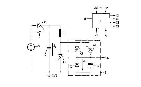
L'invention concerne un procédé et un dispositif pour la commande d'au moins un actionneur capacitif (P), en particulier une soupape d'injection de carburant de moteur à combustion interne, actionnée piézoélectriquement, au moyen d'un circuit de commande (ST) commandé par microprocesseur, comprenant un condensateur de charge (C) rechargeable par une source d'énergie (V), lequel charge le ou les actionneurs par l'intermédiaire de commutateurs (X1 à X4) commandés par le circuit de commande, et dans lequel ledit actionneur se décharge de nouveau.


Abrégé anglais


A process and device are disclosed for driving at least one capacitive
actuator (P), in particular a piezoelectrically driven fuel injection valve of
an internal combustion engine, by means of a microprocessor-controlled control
circuit (ST) with a charging capacitor (C) which can be recharged by an energy
source (V), which charges the at least one actuator through switches (X1 to
X4) controlled by the control circuit, and into which said actuator is again
discharged.

Revendications

Note : Les revendications sont présentées dans la langue officielle dans laquelle elles ont été soumises.


-7-
Claims
1. Device for driving at least one capacitive
actuator (P),
- having a charging capacitor (C), which is arranged
between the positive pole (+V) and negative pole (GND) of
an energy source (V) and can be re-charged by the energy
source (V) via an energy switch (X1),
- having a series circuit, which is arranged in
parallel with the charging capacitor (C) and comprises a
ring-around coil (L), connected to the energy switch
(X1), and a charging stop switch (X3), and
- having an actuator circuit (S, S1) arranged in
parallel with the charging stop switch (X3), comprising
- a discharging switch (X4), which is connected on one
side to the ring-around coil (L) and conducts current to
it,
- for each actuator, a series circuit composed of a
charging switch (X2.1 to X2.n), which is connected to the
ring-around coil (L) and conducts current away from it,
and the actuator (Pl to Pn) itself, and a diode (D2.1 to
D2.n), which is arranged between the actuator (Pl to Pn)
and the other side of the discharging switch (X4) and
conducts current in the discharging direction, and
- a diode (D) which is connected in parallel with one
of the actuators (Pl) and passes current in the direction
of the charging switch (X2.1) assigned to the actuator.
2. Device for driving at least one capacitive
actuator (Pl to Pn) by means of a control circuit (ST),
in particular a piezoelectrically operated fuel injection
valve of an internal combustion engine,
- having a charging capacitor (C), which is arranged
between the positive pole (+V) and negative pole (GND) of
an energy source (V) and can be re-charged by the energy
source (V) via an energy switch (X1),
- having a series circuit, which is arranged in
parallel with the charging capacitor (C) and comprises a
ring-around coil (L), connected to the energy switch
(X1), and a charging stop switch (X3),

-8-
- having an actuator circuit (S2) which is arranged in
parallel with the charging stop switch (X3) and contains
a series circuit composed of a parallel circuit of a
discharging switch (X4), which passes current to the
ring-around coil (L), and a charging switch (X2), which
passes current away from the ring-around coil (L), and of
a diode (D), and
- having a series circuit, provided for each actuator
(Pl to Pn) and arranged in parallel with the diode (D),
which is composed of the actuator (Pl to Pn) itself and
of an electronic selector switch (T1 to Tn), which is
assigned to said actuator, is controlled by the control
circuit (ST) and whose switching junction is bridged by
a diode Dl to Dn which conducts current in the discharging
direction.
3. Device according to one of Claims 1 or 2, characterized
in that the energy switch (X1), charging switch
(X2, X2*, X2.1 to X2.n) and discharging switch (X4, X4*)
comprise controlled, electronic switches which pass
current only in one direction and have at least one
semiconductor element.
4. Device according to one of Claims 1 or 2, characterizing
in that at least one desired value (Usl to Usn)
for the position of the respective actuator (P, Pl to Pn)
or for the voltage (Up) present across it can be
prescribed for the control circuit (ST) or stored in it, and
- in that the control circuit (ST) outputs the control
commands for the charging switches (X2, X2.1 to X2.n),
charging stop switch (X3), discharging switch (X4) and
selector switches (Tl to Tn) as a function of external
control signals (st) from the position of the respective
actuator (P, Pl to Pn) or of the voltage (Up) present
across it, and from the respectively prescribed desired
value (Usl to Usn) for the position or voltage of the
actuator.
5. Method for operating the device according to one
of Claims 1 or 2, characterized
in that with the start of a control signal (st) the
actuator (P, Pl to Pn) to be driven is recharged from the

-9-
charging capacitor (C), charged by the energy source (V)
via the ring-around coil (L) until the voltage (Up)
present across it reaches a prescribed desired value
(Us),
in that subsequently this state of charge (Up = Us) is
maintained up to the end of the control signal (st),
in that with the end of the control signal (st) the
actuator is discharged into the charging capacitor (C),
and
in that the charging capacitor (C) is recharged by the
energy source (V) following the discharging operation.

Description

Note : Les descriptions sont présentées dans la langue officielle dans laquelle elles ont été soumises.

CA 02263304 1999-02-12
GR 96 P 8054 Foreign ver~ion
~,
Deseription r~~ - -
Deviee and method for driving a eapacitive aetuator
The invention relates to a deviee for driving at
least one capaeitive aetuator, in partieular a
piezoeleetrieally operated fuel injeetion valve of an
internal eombustion engine in aeeordanee with the fea-
tures of Patent Claim 1 or 2. The invention also relates
to a method for operating this deviee.
EP 0 464 443 A1 discloses a piezoelectrie
actuator which i8 eharged from a eapaeitor via a eharging
eoil. During discharging of the piezoelectrie aetuator,
part of the energy applied is fed back into the eapaeitor
via a diseharging coil, while the other part is eonverted
into heat, likewise via the di~eharging eoil. During
diseharging, a negative voltage is present aeross the
piezoeleetrie aetuator.
DE 36 21 541 C2 diseloses a driver eircuit for a
piezoeleetrie aetuator of a fuel injeetion valve whieh i~
eharged via a series eireuit, eonneeted to a voltage
souree and eomposed of two eapacitors, and a charging
eoil, and is diseharged into one of the two eapaeitors
via a diseharging eoil. In an alternative design, the
aetuator is eharged via a eapaeitor, eonneeted to a
voltage souree, and a eharging eoil; during diseharging,
the energy stored in the piezoeleetrie aetuator is
destroyed by a diseharging eoil.
It is the objeet of the invention to provide a
deviee for driving at least one eapaeitive aetuator whieh
operates as far as possible without 1088 and is of simple
design, and in whieh it iB also possible to prescribe
different desired values for the voltage occurring aeros~
the aetuator, and in whieh negative voltages aeross the
aetuator are avoided.
This objeet is aehieved aeeording to the inven-
tion by means of the features of Patent Claim 1 or 2.Advantageous embodiment~ of the invention are to be
gathered from the subelaims.

CA 02263304 1999-02-12
Exemplary embodiments of the invention are
explained in more detail below with reference to the
diagrammatic drawing, in which:
Figure 1: shows the circuit of a first exemplary
~hodiment,
Figure 2: a flowchart relating to the mode of operation
of the exemplary embodiment according to
Figure 1,
Figure 3: shows the circuit of a second exemplary
embodiment, and
Figure 4: shows the circuit of a third exemplary
embodiment.
Figure 1 shows a block diagram for driving an
individual fuel in;ection valve (not shown in further
detail) of an internal combustion engine ~ia a
piezoelectric actuator P by means of a control circuit ST
which is usually controlled by microprocessor.
Connected between the positive pole +V and the
negative pole GND of an energy source V is a series
circuit composed of a charging capacitor C and a con-
trolled, electronic energy switch X1 which passes current
only in one direction.
In the further description, when switches X1 to
X4 are mentioned they are electronic switches, preferably
thyristor switches, which pass current only in one
direction, consist of at least one semiconductor element
and are driven by the control circuit ST.
In the cQ~ cting state of the energy switch X1,
the charging capacitor C is charged by the energy source
V. This can be performed in principle as long as the
voltage Uc across the charging capacitor is lower than
the voltage of the energy source V.
Connected in parallel with the charging capacitor
C is a series circuit composed of a ring-around coil L
connected to the energy switch X1, and a charging stop
switch X3, whose function will be explained later.
Arranged in parallel with the charging stop
switch X3 is an actuator circuit S which has a series
circuit which is composed of a parallel circuit

CA 02263304 1999-02-12
-- 3
comprising a charging switch X2, which passes current in
the direction away from the ring-around coil L, and a
discharging switch X4 which passes current in the direc-
tion of the ring-around coil, and of a parallel circuit
comprising the actuator P with a diode D, which passes
current in the direction of the charging ewitch X2.
The switches X1 to X4 are controlled by a micro-
processor-controlled circuit ST as a function of external
control signals st of, in this exemplary ~hodiment, a
prescribed desired value ~8 (there can also be a
plurality which become active one after another, for
example preinjection and main injection of fuel) for the
voltage present across the actuator P, and of the actual
~alue Up of this voltage. The position of the actuator
can also be used instead of the actuator ~oltage.
A method for operating the device is described on
the example of the circuit according to Figure 1 with the
aid of the flow chart shown in Figure 2, starting from an
initial state (state I) in which the charging capacitor
C is fully loaded, all the switches X1 to X4 are non-
cQn~ncting and the ring-around coil L is de-energized.
With the start of an external control signal
st = 1 (state II), the charging switch X2 is triggered
(controlled to be co~ cting). Conseguently, the charging
capacitor C starts to discharge ~ia the ring-around coil
L into the actuator (acting like a capacitor), and to
charge said actuator (state III), the effect being to
change the length of the piezoelectric actuator. There is
an increase in the voltage Up present across the
actuator, which is communicated to the control circuit ST
(indicated by arrows in Figure 1).
As soon as the voltage Up reaches the desired
value U~ (state IV), the charging operation is
terminated, the charging switch X2 becomes non-
conducting, that is to say X2 = 0, and the charging stopswitch X3 become~ conducting (X3 = 1, state V). The
resonant circuit L-C continues to oscillate until the
ring-around coil L i8 de-energized.
The state of charge of the actuator is maintained

CA 02263304 1999-02-12
ae long as the control signal st is present. When it
vanishes (st = 0, etate VI), the actuator must be die-
charged. For this purpoee, the charging etop ewitch is
controlled to be non-eon~n~ting, X3 = 0, and the dis-
charging switch to be conducting, X4 - 1 (state VII). The
actuator P i8 now discharged via the ring-around coil L
into the charging capacitor C. If the actuator i~ dis-
charged down to the threehold voltage of the diode D, the
latter ta~ee over the current; the ree~nt circuit L-C
cont;n~e~ to oecillate until the ring-around coil ie de-
energized. The ewitch X4 ie controlled to be non-
c~n~cting.
In the abeence of lossee, the same voltage ~cwould now be preeent acroee the charging capacitor C as
in the initial state I. In fact, however, becauee of
losses it has become eomewhat lower, with the result
that, in this exemplary ~bodiment, after termination of
the discharging operation, when the switchee X2 to X4 are
once again non-conducting, the energy ewitch X1 ie
switched to be conducting to recharge the charging
capacitor C (state VIII) before a new charging cycle
begins.
Figure 3 ehows a circuit correspo~; ng in prin-
ciple to the c~rcuit according to Figure 1, but for
driving a plurality of actuators P1 to Pn. In this
circuit, the energy source V, energy switch X1, charging
capacitor C, ring-around coil and charging stop switch X3
are connected as in the case of the circuit according to
Figure 1 and acte just ae described there. However, the
control circuit ST is not represented again here.
For the first actuator P1, the actuator circuit
S1 with the charging switch X2.1 instead of X2, the diode
D and the diecharging switch X4 has the same circuit as
in Figure 1, with the difference that there ie conneeted
between the actuator P1 and discharging switch X4 a diode
D2.1 which conducts current towarde the discharging
switch and is not required for driving only one actuator
according to Figure 1, and that for each further actuator
P2 to Pn a further charging switch X2.2 to X2.n and a

CA 02263304 1999-02-12
further diode D2.2 to D2.n are provided in an appropriate
circuit.
The charging switches X2.1 to X2.n driven by the
control circuit select the actuator to be charged, while
the diodes D2.1 to D2.n prevent other actuators than the
selected one from also being charged. Each actuator iB
di~charged via the diode D2.1 to D2.n assigned to it when
the common discharging switch X4 is controlled to be
conductive. If the respective actuator is discharged down
to the threshold voltage of the diode D, the latter takes
over the current; the re~onant circuit L-C continues to
oscillate until the ring-around coil L is de-energized.
Figure 4 shows a further circuit for driving a
plurality of actuators which have a reduced component
outlay by comparison with the circuit according to Figure
3. Once again, the control circuit ST is also not shown
here.
The circuit according to Figure 3 requires an
expensive tran~former to trigger each of the thyristor
switches X2.1 to X2.n. These transformers are dispensable
if, instead of them, use is made of simple selector
switches T1 to Tn, for example power NOSFET switches. The
circuit i~ then essentially reduced to a circuit cor-
respQn~ing to the circuit according to Figure 1, in which
the actuator P is replaced by a serie~ circuit composed
of an actuator P1 and an assigned selector switch T1,
there being connected in parallel with the switc~;ng
junction of the selector switch T1 a diode D1 which
passes current in the discharging direction and is
already integrated in MOSFET ~witches when they are used.
Such a series circuit composed of an actuator P2
to Pn, a selector switch T2 to Tn and a diode D2 to Dn i8
connected, for each further actuator P2 to Pn, in paral-
lel with the series circuit P1-Tl-Dl for the first
actuator P1.
The mode of operation of this circuit corresponds
to that of the circuits according to Figure~ 1 and 3, it
being the case that during charging of an actuator, for
example P1, the a~signed selector ~witch T1 must be

CA 02263304 1999-02-12
controlled to be conducting for at least as long as the
charging switch X2 i8 controlled to be conducting.
During discharging of the actuator Pl, the
current flows from the actuator via the discharging
switch X4, ring-around coil L, charging capacitor C and
diode D1. If the actuator is discharged down to the
threshold voltage of the diode D, the latter takes over
the current and the resonant circuit L-C continues to
o~cillate until the ring-around coil is de-energized.
By means of cimple change~ both to the charging
and discharging switches and to the selector switches,
the circuits shown in F~gures 1, 3 and 4 can be designed
such that, depsn~;ng on the preconditions, the actuators
are either co~nerted to the negative pole GND (low side,
~ee Figures 1 and 3), or are situated closer to the
positive pole +V (high sido, see Figure 4).

Dessin représentatif
Une figure unique qui représente un dessin illustrant l'invention.
États administratifs

2024-08-01 : Dans le cadre de la transition vers les Brevets de nouvelle génération (BNG), la base de données sur les brevets canadiens (BDBC) contient désormais un Historique d'événement plus détaillé, qui reproduit le Journal des événements de notre nouvelle solution interne.

Veuillez noter que les événements débutant par « Inactive : » se réfèrent à des événements qui ne sont plus utilisés dans notre nouvelle solution interne.

Pour une meilleure compréhension de l'état de la demande ou brevet qui figure sur cette page, la rubrique Mise en garde , et les descriptions de Brevet , Historique d'événement , Taxes périodiques et Historique des paiements devraient être consultées.

Historique d'événement

Description Date
Inactive : CIB expirée 2023-01-01
Inactive : CIB de MCD 2006-03-12
Demande non rétablie avant l'échéance 2002-08-05
Le délai pour l'annulation est expiré 2002-08-05
Réputée abandonnée - omission de répondre à un avis sur les taxes pour le maintien en état 2001-08-06
Inactive : CIB en 1re position 1999-04-13
Inactive : CIB attribuée 1999-04-13
Symbole de classement modifié 1999-04-13
Inactive : Acc. récept. de l'entrée phase nat. - RE 1999-03-29
Demande reçue - PCT 1999-03-26
Exigences pour une requête d'examen - jugée conforme 1999-02-12
Toutes les exigences pour l'examen - jugée conforme 1999-02-12
Demande publiée (accessible au public) 1998-02-19

Historique d'abandonnement

Date d'abandonnement Raison Date de rétablissement
2001-08-06

Taxes périodiques

Le dernier paiement a été reçu le 2000-07-18

Avis : Si le paiement en totalité n'a pas été reçu au plus tard à la date indiquée, une taxe supplémentaire peut être imposée, soit une des taxes suivantes :

  • taxe de rétablissement ;
  • taxe pour paiement en souffrance ; ou
  • taxe additionnelle pour le renversement d'une péremption réputée.

Veuillez vous référer à la page web des taxes sur les brevets de l'OPIC pour voir tous les montants actuels des taxes.

Historique des taxes

Type de taxes Anniversaire Échéance Date payée
Requête d'examen - générale 1999-02-12
Taxe nationale de base - générale 1999-02-12
Enregistrement d'un document 1999-02-12
TM (demande, 2e anniv.) - générale 02 1999-08-05 1999-07-23
TM (demande, 3e anniv.) - générale 03 2000-08-07 2000-07-18
Titulaires au dossier

Les titulaires actuels et antérieures au dossier sont affichés en ordre alphabétique.

Titulaires actuels au dossier
SIEMENS AKTIENGESELLSCHAFT
Titulaires antérieures au dossier
CHRISTIAN HOFFMANN
GEORG BRASSEUR
HARTMUT GERKEN
HELLMUT FREUDENBERG
RICHARD PIRKL
Les propriétaires antérieurs qui ne figurent pas dans la liste des « Propriétaires au dossier » apparaîtront dans d'autres documents au dossier.
Documents

Pour visionner les fichiers sélectionnés, entrer le code reCAPTCHA :


Pour visualiser une image, cliquer sur un lien dans la colonne description du document. Pour télécharger l'image (les images), cliquer l'une ou plusieurs cases à cocher dans la première colonne et ensuite cliquer sur le bouton "Télécharger sélection en format PDF (archive Zip)" ou le bouton "Télécharger sélection (en un fichier PDF fusionné)".

Liste des documents de brevet publiés et non publiés sur la BDBC .

Si vous avez des difficultés à accéder au contenu, veuillez communiquer avec le Centre de services à la clientèle au 1-866-997-1936, ou envoyer un courriel au Centre de service à la clientèle de l'OPIC.


Description du
Document 
Date
(aaaa-mm-jj) 
Nombre de pages   Taille de l'image (Ko) 
Abrégé 1999-02-12 1 62
Description 1999-02-12 6 265
Revendications 1999-02-12 3 110
Dessins 1999-02-12 3 40
Page couverture 1999-04-30 1 41
Dessin représentatif 1999-04-30 1 5
Rappel de taxe de maintien due 1999-04-07 1 111
Avis d'entree dans la phase nationale 1999-03-29 1 202
Courtoisie - Certificat d'enregistrement (document(s) connexe(s)) 1999-03-29 1 117
Courtoisie - Lettre d'abandon (taxe de maintien en état) 2001-09-04 1 185
PCT 1999-02-12 10 346