Note : Les descriptions sont présentées dans la langue officielle dans laquelle elles ont été soumises.
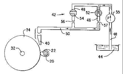
1015202530CA 02264506 1999-03-02wo 93/09772 PCT/IJ S97/ 151 18VARIABLE VOLUME COOLANT SYSTEMField of the InventionThis invention pertains generally to systems fordelivering liquid Coolants to the interface defined between amachine tool and a workpiece to be abraded to a desired size andcurvature. More particularly, this invention relates to a systemthat delivers variable volumes of coolant, at different times,in the cycle of operation of the machine tool.Background of the InvggtignSystems for delivering liquid coolants, such as water,oil, or combinations thereof, to rotating tools, such as grindingwheels, are well known. Such systems usually deliver the liquidcoolant, through a nozzle situated in proximity to the grindingwheel. A pump withdraws the liquid coolant from a reservoir, andpressurizes same before its discharge through a strategicallylocated nozzle.The liquid coolant serves many functions; forexample, the coolant may cool the workpiece and lubricate thetool, or vice versa, and the coolant may drive away the debrisor "swarf",formed between the tool and workpiece. The liquidcoolant discharged, however, is usually constant in volume, andthus does not take into account different conditions that occurduring the cycle of operation.To illustrate, U.S. Patent 2,140,838, ï¬art, disclosesa coolant delivery system that supplies a cooling liquid, suchas water, to a cutting tool, such as broach 16, 22, to cool,lubricate, and clear chips away from the tool. The coolantdelivery system includes two pipes 24, 26 which are connected topumps 28, 30; the two pipes are joined together in the vicinityof the working face of the broach, as shown in FIG. 2. Arelatively large quantity of cooling fluid is delivered, under10152025CA 02264506 1999-03-02WO 98/09772 PCT/US97/151182relatively low pressure, through pipe 24 to prevent overheatingof the broach. Simultaneously, a relatively fine stream ofrelatively high velocity cooling fluid is directed through pipe26 to forcibly drive chips out of, and away from, the face of thebroach.As another example of known coolant systems for tools,such. as cutting tools, U.S. Patent 5,228,369, Itoh. et al,discloses an assembly for machining a substrate surface of aphotoreceptor 1, such as a drum for a photocopier, laser printer,or the like. The assembly supplies cutting lubricant from areservoir 5 to the cutting tool 3 for the assembly. The methodof machining calls for measuring the temperature of the cuttingtool by a sensor 4, such as a thermocouple, and control of boththe temperature and flow rate, by temperature control unit 6 andflow control unit 7. The control unit 6 is responsive to thecutting tool temperature and suppresses a temperature fluctuationof the cutting tool, as suggested in FIG. 6.Another known coolant delivery system is disclosed inU.S. Patent 2,434,679, Wagner et al, which discloses a systemthat supplies low pressure liquid over pipeline 3 to nozzle 12,while simultaneously supplying high pressure liquid over pipeline25 to nozzles 19, 20, 21. The high pressure nozzles are locatedwithin the low pressure nozzle 12, as shown in FIG. 5, and thenozzles discharge the two coolant liquids, at the same time, fromthe common outlet at the lower end of nozzle 12. Two separateliquids, such. as water and oil, are used, for cooling andlubricating. The liquids are immiscible, and are kept separate,by using individual recirculation loops.1015202530CA 02264506 1999-03-02W0 98l09772 PCT/US97/151183SUMARY OF THE INVENTIONIn contrast to known fixed volume systems used fordelivering coolant to the interface between a machine tool, suchand a workpiece,as a grinding wheel, such as a camshaft,crankshaft, or the like, the instant invention discloses a methodfor delivering variable volumes, of liquid coolant, at differenttimes in the machining cycle. The novel method correlates thevolume of fluid to be delivered, to the amount of metal remainingto be removed, or to the rate at which said metal is removed,before the machining operation is completed. By reducing thevolume of liquid coolant discharged as the machining operationapproaches its conclusion, the instant invention permits thegrinding wheel to snugly Contact the workpiece to obtain closertolerances and more accurate geometry.The system for implementing the instant inventionrelies upon two, or more, volume controlled paths for deliveringsuch as a reservoir,liquid coolant from a common supply, or asupply line to a nozzle. The nozzle delivers large volumes ofcoolant during high stock removal points in the machining cycle,while the other path delivers low volumes of coolant when stockremoval is low and the final geometry is being created. The lowvolume of coolant flow reduces the forces imposed on theworkpiece by the coolant being pressed. thereagainst by themachine tool, such as the grinding wheel. The coolant trappedin the Vâshaped notch or gap defined between the workpiece andthe machine tool transmits forces to the workpiece that hamperaccurate machining thereof. The exceedingly tight tolerancesrequired by automotive manufacturers sparked the need toinvestigate every potential avenue for improving tolerances, evenby millionths of an inch.l0l520253035CA 02264506 2004-06-034Other advantages that are attributable to the instant,conceptually distinguishable system for delivering variable volumesof liquid coolants, at different times in the machining cycle, willbecome apparent to the skilled artisan from the appended drawings,when construed in harmony with the ensuing description.According to the present invention then there is provideda system for delivering coolant to the working surfaces of amachine tool and a workpiece with eccentric surfaces to be machinedto a desired size and shape, said machine tool including a bed, acarriage, means on said carriage adapted to receive and retain theworkpiece,said bed,said carriage being movable in a first direction alonga tool carriage, said machine tool secured to said toolcarriage, and drive means mounted on said tool carriage foradvancing said tool carriage in a second direction, perpendicularto said first direction, so that said tool contacts said workpiece,motor means on said tool carriage for driving said tool so thatsaid tool abrades said workpiece, a source of liquid coolant, anozzle for delivering coolant to the gap defined between saidconnectedmachine tool and said. workpiece, and conduit meansbetween said source and said nozzle, first valve means forregulating the flow of coolant through said conduit means todeliver a first volume of liquid coolant through said nozzle intosaid gap during the nachine operation, second valve means forregulating the flow of coolant through said. conduit means todeliver a second volume of liquid coolant through said nozzle intosaid gap during the machining operation, and said second valvemeans being connected in series with a restriction in said conduitmeans to reduce the volume of coolant flow to a level less than thevolume of flow through said first valve means.According to another aspect of the present invention,there is provided a system for delivering coolant to the workingsurfaces of a machine tool and a workpiece with eccentric surfacesto be machined to a desired size and shape, said machine toolincluding a bed, a carriage, means on said carriage adapted toreceive and retain the workpiece, said carriage being movable ina first direction along said bed,a tool carriage, said machine1O1520253035CA 02264506 2004-06-034atool secured to said tool carriage, and drive means for advancingsaid tool carriage in a second direction, perpendicular to saidfirst direction, so that said tool contacts said workpiece, motormeans on said carriage for driving said machine tool so that saidtool abrades said workpiece, a source of liquid coolant, a nozzlefor delivering coolant to the gap defined between said machine tooland and first andsaid workpiece, second conduit paths, ofdifferent volumes, connected between said source and said nozzle,first valve means for regulating the flow of coolant through saidfirst conduit path to deliver a first volume of liquid coolantthrough said nozzle into said gap during the machining operation,second valve means for regulating the flow of coolant through saidconduit means to deliver a second volume of liquid coolant throughsaid nozzle into said gap during the machining operation, and saidfirst and second conduit paths terminating in an inlet pipe thatfeeds into said nozzle, which is common to both conduit paths.According to yet another aspect of the present inventionthere is also provided a system for delivering fluid to the workingsurfaces of a machine tool and a workpiece to be machined to adesired size and shape, said machine tool includimg a bed, acarriage, means on said carriage adapted to receive and retain theworkpiece, the carriage being moveable along a first path withrespect to said bed, a tool carriage, a tool secured to said toolcarriage, and drive means carried by said tool carriage for movingsaid tool carriage along a second path with respect to said firstpath, so that said tool contacts said workpiece, operating meanson said tool carriage for operating said tool so that said toolabrades said workpiece, a source of fluid, a nozzle for deliveringsaid fluid into a gap defined between said machine tool and saidworkpiece, and conduit means connected between said source and saidnozzle, and valve means for regulating the flow of fluid throughsaid conduit means to deliver a first volume of fluid through saidnozzle into said gap during the machining operation, said valvemeans further regulating the flow of fluid through said conduitmeans to deliver a second volume of fluid through said nozzle intosaid gap during the machining operation, and said valve meansl0152O2530CA 02264506 2004-06-034bincluding a restriction connected in series in said conduit meansto reduce the volume of fluid flow of fluid through said conduitmeans, wherein said valve means include a first valve fordelivering said first volume of fluid and a second valve fordelivering said second volume of fluid, said first and secondvalves being connected by said conduit means to the same source offluid.According to yet a further aspect of the presentinvention, there is provided a system for delivering coolant to theworking surfaces of a machine tool and a workpiece with eccentricsurfaces to be machined to the desired size and shape, said machinetool including a bed,a carriage, means on said carriage adaptedto receive and retain the workpiece, said carriage being movablein a first direction along said bed, a tool carriage, a toolsecured to said tool carriage, and drive means for advancing saidtool carriage in a second direction, perpendicular to said firstdirection, so that said tool contacts said workpiece, motor meanson said carriage for driving said machine tool so that said toolabrades said workpiece, a source of liquid coolant, a nozzle fordelivering coolant to the gap defined between said machine tool andsaid workpiece, and first and second conduit paths, of differentvolumes, connected between said source and said nozzle, first valvemeans for regulating the flow of coolant through said first conduitpath to deliver a first volume of liquid coolant through saidnozzle into said gap during the machining operation, second valvemeans for regulating the flow of coolant through said conduit meansto deliver a second volume of coolant through said nozzle into saidgap during the machining operation, and said first and secondconduit paths terminating in an inlet pipe that feeds into saidnozzle, which is common to both conduit paths.lOCA 02264506 1999-03-02WO 98/09772 PCT/US97/151 185BRIEF DESCRIPTION OF THE DRAWINGSFIG. 1 is a schematic View of a Inachining systemincluding a grinding wheel, a carriage to advance the grindingwheel into contact with a workpiece, and a nozzle for dischargingcoolant onto the workpiece and the grinding wheel;on an enlarged scale, ofFIG. 2 is a schematic view,a control system, including two valves, for regulating the flowof coolant to the nozzle during high volume discharge; andFIG. 3 is a similar View of the control system, butshowing the two valves, in different conditions,volume discharge.during low.1015202530CA 02264506 1999-03-02wo 93/09772 PCT/US97/151 186DESCRIPTION OF A PREFERRED EMBODIMENT OF THE INVENTIONFIG. 1 depicts a schematicâ representation of aconventional machine tool, such as a grinding machine, indicatedgenerally by reference numeral 10. Machine 10 comprises a heavymetal base 12, that is secured in position on a factory floor.A front wall 13 extends upwardly from base 12, and a first slide14 is situated atop wall 13. A second slide 16 rests atop plate14, and a carriage 18 is movable transversely relative to slides14, 16.The carriage includes a head stock, a chuck on theheadstock, a tail stock, and a second chuck on the tail stock,and a drive spindle for driving the head stock and the tailstock, but such components are omitted from FIG. 1. The oppositeends of the shaft 20 of the workpiece are inserted into, andgrasped by the chucks, so that the eccentric surfaces 22 of theworkpiece are retained in fixed position during machiningoperations.Machine 10 also includes a drive motor 24, and a shaftand lead screw drive mechanism) 26 for advancingâ wheel headcarriage 28,along pad 30. Axle 32 of grinding wheel 34, whichmay be made of CBN or similar abrasive materials, is secured tocarriage 28. Motor 24, when energized, advances, or retracts,wheel head carriage 28 in the longitudinal direction, so thatwheel 34 can grind the eccentric surfaces 22 of the workpiece tothe desired size and shape.Motor 36, via endless belt 38,delivers the motive power to wheel 34, for precise, high speedgrinding, after the carriage 28 has been advanced to the properposition.Nozzle 40 is positioned above the point of contact forthe grinding wheel and the workpiece. The nozzle delivers liquidcoolant, usually a water based fluid or oil, to the grinding1015202530CA 02264506 1999-03-02W0 98l09772 PCT/US97/151187wheel and to the workpiece, in order to cool same, and to washaway debris, commonly known as "swarf "FIG. 2 and FIG. 3 show, in a schematic manner, the flowcontrol system 42 for delivering a variable volume of coolant tonozzle 40 for discharge. The flow control system includes areservoir 44, or other common pressure source, connected toconduits 46, 48 that lead into common pipe 50 that terminates in40.nozzle A first valve 52 is situated in conduit 46, while asecond valve 54 is situated in conduit 48. Flow restrictingcomponents, such as restrictor 56 in line 58, are connected inseries with valve 52. .FIG.2 shows valve 54 in its open condition, whilevalve 52 is jJ1 its closed position. Punm> 55 causes liquidcoolant to flow from reservoir 44 through conduit 48, valve 54,restrictor 56, into common pipe 50, and thence into nozzle 40.Such flow path for liquid coolant allows high volume discharge,for an extended period of time over the stock removal phase ofthe machining operation.The coolant forms a hydrodynamic wedge between the22 and the grinding wheel 34.workpiece 20, The forces pressingthe machine tool, such as grinding wheel 34, against theworkpiece, such as cam or lobe 22 on camshaft 20, are far greaterthan the forces represented by the hydrodynamic wedge, so thatthe wedge has negligible impact on the stock removing phase ofthe machining operation.However,as the workpiece 20, 22 approaches its finalsize and geometry, the hydrodynamic wedge interferes with thecapability of the machine to properly shape the workpiece, in itsfinal phase. To overcome the effect of the wedge, and to obtainthe desired workpiece size and geometry, flow control system 42reverses the orientation of valves 52 and 54. As shown in FIG.l015202530CA 02264506 1999-03-02wo 98/09772 PCT/US97/1511883, valve 54 is shut to block flow through conduit 48, while valve52 is opened to allow flow through conduit 46, into common pipe50, and thence into nozzle 40. Flow restrictor components, suchas restrictor 56 in line 58 and/or restrictor 57 in conduit 46,insure that a lesser volume of coolant reaches nozzle 40 to bedischarged between the workpiece and machine tool. The lesservolume of coolant reduces the impact of the hydrodynamic wedge,and allows the machine tool to contact, or "kiss" the workpiece,so that the final few millionths of material can be removed withunparalleled accuracy.Although FIG. 2 and FIG. 3 are only schematic drawings,the "normal" flow rate for the coolant, under normal operatingconditions for a known machine tool, such as a grinding wheel,the low flow rate54,was 30 gallons per minute/inch. In contrast,of coolant was 5 gallons per minute/inch. Valves 52, are,preferably, solenoid valves, and the operation and timing of suchvalves, is correlated with the cycle of operation for the machinetool. The utilization of two flow rates, increased the abilityof the machine tool to control size and roundness by 20 milâlionths of an inch, a significant improvement in a highlycompetitive, and cost conscious, metal machining industry.Although flow control system 42 is capable of discharg-ing two distinct volumes of coolant, over two distinct pathsleading to nozzle 40, the flow control system may be expanded,by using additional solenoid valves, or variable volume controlvalves, to discharge three or more distinct volumes of coolant.Additionally, although the variable volume coolant system ispresented in cooperation with a grinding system, the coolantsystem is equally applicable to other machining systems.Furthermore, in practice, both valves 52, 54 are opened duringhigh volume operation, so that the total volume of coolantCA 02264506 1999-03-02W0 98l09772 PCT/US97/151189delivered by nozzles 40 is the sum of both flow paths. Thisprocedure guarantees that there is no "dry" period when thecoolant system is switched to low volume, for low volume flow maybe maintained at all times during the machining cycle. Conse-quently, the appended claims should be broadly construed, andshould not be limited to their literal terms.