Sélection de la langue

Search

Sommaire du brevet 2264593 

Énoncé de désistement de responsabilité concernant l'information provenant de tiers

Une partie des informations de ce site Web a été fournie par des sources externes. Le gouvernement du Canada n'assume aucune responsabilité concernant la précision, l'actualité ou la fiabilité des informations fournies par les sources externes. Les utilisateurs qui désirent employer cette information devraient consulter directement la source des informations. Le contenu fourni par les sources externes n'est pas assujetti aux exigences sur les langues officielles, la protection des renseignements personnels et l'accessibilité.

Disponibilité de l'Abrégé et des Revendications

L'apparition de différences dans le texte et l'image des Revendications et de l'Abrégé dépend du moment auquel le document est publié. Les textes des Revendications et de l'Abrégé sont affichés :

  • lorsque la demande peut être examinée par le public;
  • lorsque le brevet est émis (délivrance).
(12) Brevet: (11) CA 2264593
(54) Titre français: DISPOSITIF DE FILTRATION ETAGE POUR LA SEPARATION MECANIQUE DE SOLIDES CONTENUS DANS DES LIQUIDES
(54) Titre anglais: STEPPED FILTRATION DEVICE FOR MECHANICALLY SEPARATING SOLIDS FROM LIQUIDS
Statut: Réputé périmé
Données bibliographiques
(51) Classification internationale des brevets (CIB):
  • E02B 5/08 (2006.01)
  • E02B 8/02 (2006.01)
  • E03F 5/14 (2006.01)
(72) Inventeurs :
  • GIERSBERG, ALFRED (Allemagne)
(73) Titulaires :
  • KUHN, MICHAEL (Allemagne)
  • KUHN, JURGEN (Allemagne)
(71) Demandeurs :
  • EGNER UMWELTTECHNOLOGIE GMBH (Allemagne)
(74) Agent: KIRBY EADES GALE BAKER
(74) Co-agent:
(45) Délivré: 2005-12-27
(86) Date de dépôt PCT: 1998-04-29
(87) Mise à la disponibilité du public: 1998-11-12
Requête d'examen: 2002-04-24
Licence disponible: S.O.
(25) Langue des documents déposés: Anglais

Traité de coopération en matière de brevets (PCT): Oui
(86) Numéro de la demande PCT: PCT/DE1998/001184
(87) Numéro de publication internationale PCT: WO1998/050638
(85) Entrée nationale: 1999-03-01

(30) Données de priorité de la demande:
Numéro de la demande Pays / territoire Date
197 19 371.4 Allemagne 1997-05-07

Abrégés

Abrégé français

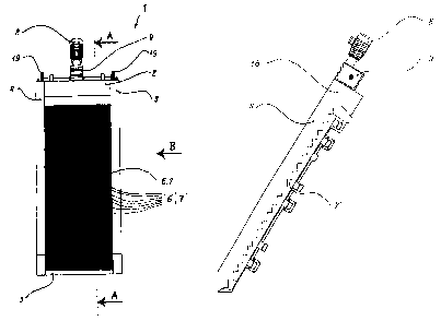
L'invention concerne un dispositif de filtration étayé (1) pour la séparation mécanique des solides contenus dans des liquides s'écoulant dans les égouts, rigoles ou conduits. Ce dispositif comporte de nombreuses barres de grille de retenue étagées (7') reliées en une grille fixe (7) et de nombreuses barres de grille de retenue étagées (6') reliées en une grille mobile (6), les grilles (6, 7) étant inclinées dans le sens d'écoulement à l'intérieur du liquide s'écoulant à partir d'un niveau situé sous la surface et les barres (6', 7') étant placées en escalier et orientées vers l'écoulement entrant. On peut actionner la grille mobile (6) avec un dispositif d'entraînement (8) sur une voie qui permet, à partir d'une position zéro identique à la grille fixe (7) en sens vertical et horizontal, un mouvement d'élévation au-dessus des paliers des barres étagées (7') reliées en grille fixe (7) et à l'opposé du sens dirigé vers l'écoulement entrant jusqu'à au moins une position identique à l'étage suivant de la grille fixe (7) en sens vertical et horizontal, puis qui ramène à la position zéro les barres (6') de la grille mobile (6) en dessous de la grille fixe (7). La grille fixe (7) est entourée, au moins latéralement, de parties de cadre (3, 4). Le dispositif est caractérisé en ceci que tous les éléments de commande (11, 12, 19, 13) de la grille mobile (6) sont disposés pratiquement dans le plan commun formé par la grille fixe (7) et la grille mobile (6) en position zéro.


Abrégé anglais


A staged filter apparatus for mechanically
separating solids from liquids flowing in channels,
gutters or conduits, which has a multiplicity of stage
screen bars connected to form a stationary grating, and
a multiplicity of stage screen bars connected to form a
movable grating, the gratings being arranged inclined
in the direction of flow inside the flowing liquid
starting from a level situated below the surface, and
the stage screen bars being constructed in a stepped
fashion in the direction facing the incoming flow, and
in which the movable grating can be actuated by means
of a drive device on a track which, starting from a
zero position which is identical in the vertical and
horizontal directions to the stationary grating,
permits a stroke movement which rises over the stages
of the stage screen bars connected to form the
stationary grating and against the direction facing the
incoming flow, and which reaches at least to a position
identical in the vertical direction and in the
horizontal direction to the next higher stage of the
stationary grating, and subsequently guides the stage
screen bars of the movable grating below the stationary
grating back into the zero position, the stationary
grating being surrounded at least laterally by frame
parts, is distinguished in that all the drive elements
of the movable grating are essentially arranged in the
common plane formed by the stationary grating and the
movable grating in the zero position.

Revendications

Note : Les revendications sont présentées dans la langue officielle dans laquelle elles ont été soumises.


-8-


CLAIMS


1. Staged filter apparatus for mechanically separating
solids from liquids flowing in channels, gutters or
conduits, which has a multiplicity of stage screen bars
connected to form a stationary grating, and a multiplicity
of stage screen bars connected to form a movable grating
moved by a series of drive elements, the gratings being
arranged inclined in the direction of flow inside the
flowing liquid starting from a level situated below a
surface of the liquid, and the stage screen bars being
constructed in a stepped fashion in the direction facing the
incoming flow, and in which the movable grating can be
actuated by means of a drive device on a track which,
starting from a zero position which is identical in the
vertical and horizontal directions to the stationary
grating, permits a stroke movement which rises over the
stages of the stage screen bars connected to form the
stationary grating and against the direction facing the
incoming flow, and which reaches at least to a position
identical in the vertical direction and in the horizontal
direction to the next higher stage of the stationary
grating, and subsequently guides the stage screen bars of
the movable grating below the stationary grating back into
the zero position, the stationary grating being surrounded
at least laterally by frame parts, characterized in that
- all the drive elements of the movable grating
are essentially arranged in the common plane formed by the
stationary grating and the movable grating in the zero
position.


-9-


2. Apparatus for mechanically separating solids
according to Claim l, characterized in that
- the drive elements include driven wheels
mounted on the frame parts of the stationary grating, the
movable grating being pivoted at the wheels in an eccentric
fashion and radially relative to axles of the wheels.

3. Apparatus for mechanically separating solids
according to Claim 2, characterized in that
- the movable grating is connected to at least
one cheek running essentially parallel to the frame parts,
and the cheek is connected to the wheels in an eccentrically
rotatable fashion in the manner of a connecting rod.

4. Apparatus for mechanically separating solids
according to Claim 3, characterized in that
- the drive is performed via chain drives
acting on the wheels or the at least one cheek.
5. Apparatus for mechanically separating solids
according to Claim 3, characterized in that
- the drive is performed via cardan shafts
acting on the wheels or the at least one cheek.

6. Apparatus for mechanically separating solids
according to Claim 1, characterized in that
- at its outermost positions, the movement
track from the zero position to the higher stage and back
leaves the plane defined by the stationary grating by no
more than double the stage height of the stage screen bars.

7. Apparatus for mechanically separating solids
according to Claim 3, characterized in that
- the at least one cheek is pivoted on the
outside at the lateral frame part(s).


-10-


8. Apparatus for mechanically separating solids
according to Claim 3 or 7, characterized in that
- seen in a side view, the at least one cheek
is present essentially in the same position as the stage
screen bars of the movable grating.

9. Apparatus for mechanically separating solids
according to Claim 3, wherein the movable grating is
connected to two cheeks.

Description

Note : Les descriptions sont présentées dans la langue officielle dans laquelle elles ont été soumises.

101520253035CA 02264593 2005-09-15Stepped Filtration Device for MechanicallySeparating Solids From LiquidsTECHNICAL FIELDThe invention relates to a stagedapparatuspresentfilter for mechanically separating solidsfrom liquids flowing in channels,which has a multiplicity of stage screen bars connectedgutters or conduits,to form a stationary grating, and a multiplicity ofstage screen bars connected to form a movable grating,the gratings being arranged inclined in the directionof flow inside the flowing liquid starting from a levelsituated below the surface, and the stage screen barsbeing constructed in a stepped fashion in the directionfacing the incoming flow, and in which the movablegrating can be actuated by means of a drive device on atrack which, starting front a zero position which isidentical in the vertical and horizontal directions tothe stationary grating, permits a stroke movement whichrises the the 2connected to form: the stationary’ grating and againstthereaches atvertical direction and inover stages of stage screen barsdirection facing the incoming flow, and whichleast to a position identical in thethe horizontal direction tothe next higher stage of the stationary grating, andthe themovable grating below the stationary grating back intothe thesurrounded at least laterally by frame parts.subsequently guides stage screen bars ofzero position, stationary grating beingPRIOR ARTSuch apparatuses are known as stage screens andserve the purpose inside sewage or separation plants ofremoving solids present in sewage. 2101520253035CA 02264593 1999-03-01_ 2 _EP 0 098 820 has disclosed a stage filter inwhich the drive device is present on the top side ofthe gratings, the movement of the movable grating beingtransmitted via an eccentric wheel and a support devicewhich is connected to said eccentric wheel and embracesthe stationary grating from above and outside.The customary designs of such devices have thedisadvantage that a relatively large overall height isprovided in each case. Given a relatively large strokeof such screens, which reaches over a plurality ofstages, the drive elements are fitted far above thegratings so that sufficient headroom is still availablefor the passage even of relatively large solid bodiesbetween the drive element and the moving gratings.However, such a construction also entails correspondingdimensioning of the channel cross-sections and theintakes, which in turn substantially increases theoutlay and the costs for setting up the intakestructures for, for example, sewage plants.DE 40 01 859 C2 has disclosed a .filter screenfor removing solid constituents from flowing liquids,in which there is arranged below the grating bars acrank drive which controls the movement of the movableThesupported in this case on skids which are mounted ingrating bars. selected lever arrangement isguide sections of the supporting structure.WO 94/24373 haswhich theeccentrically on the top side to a wheel,filterconnecteddisclosed a stagedscreen in movable grating isthere beingconnected to said wheel, likewise eccentrically, a longthin rod which,other end region via chains,in turn, is mounted on the frame at theand thereby transmits atype of elliptical rotary movement onto the movablegrating in this region. Since an essentially circularmovement of the individual stages proceeds in theregion of the upper eccentric connection of the movablegrating and an elliptical movement proceeds in thebars indifferentlowervregion,thethe course of the stage screenlongitudinal direction necessitates1015202530CA 02264593 2004-06-15_3_section designs in order to ensure reliable removal.Furthermore, the chain bearing of the connecting rod is notoptimum in the lower region as regards permanently reliablefunctioning.SUMMARY OF THE INVENTIONProceeding from said prior art, the invention isbased on the object or the technical problem of proposing astage screen in which the space requirement necessary forreliable operation is minimized and, at the same time, thepassage of even relatively large solid bodies is renderedpossible without any problem in conjunction with anarbitrarily steep inclination in the direction of flow. Inthis case, the construction is intended to be of simple,robust and low—maintenance design.The staged filter apparatus according to theinvention has a multiplicity of stage screen bars connectedto form a stationary grating, and a nmltiplicity of stagescreen bars connected to form a movable grating moved by aseries of drive elements, the gratings being arrangedinclined in the direction of flow inside the flowing liquidstarting from a level situated below a surface of theliquid, and the stage screen bars being constructed in astepped fashion in the direction facing the incoming flow,and in which the movable grating can be actuated by means ofa drive device on a track which, starting from a zeroposition which is identical in the vertical and horizontaldirections to the stationary grating, permits a strokemovement which rises over the stages of the stage screenbars connected to form the stationary grating and againstthe direction facing the incoming flow, and which reaches atleast to a position identical in the vertical direction andL0152025CA 02264593 2004-06-15_ 3a _in the horizontal direction to the next higher stage of thestationary grating, and subsequently guides the stage screenbars of the movable grating below the stationary gratingback into the zero position, the stationary grating beingsurrounded at least laterally by frame parts, characterized- all the drive elements of the movable grating arethein thatessentially arranged in common plane formed by thestationary grating and the movable grating in the zeroposition.The device according to the invention formechanically separating solids from liquids is thereforedistinguished in that all the drive elements of the movablegrating are essentially arranged in the common plane formedby the stationary grating and the movable grating in thezero position.The result of such a construction of the apparatusis a modular design in which the entire apparatus includingthe drive can be installed and operated as components whichare immediately ready to function inside channel cross-sections which are bounded only by the simplest lateralstructures or lateral holding constructions, without theneed to set up complicated structures or gutter guides,machine boxes or housings, controls or gear internals ordevices for accessory parts.The modular design likewise permits easyinstallation in already existing systems, for example101520253035CA 02264593 1999-03-01- 4 _when wear in the old plant necessitates replacement ofthe screen devices, and is therefore eminently suitablefor adapting gutter cleaning systems to sewagefractions which have changed in the course of recentbutthealso to new statutorythedecades, for example,regulations regarding further disposal oftreated waters.Moreover, owing to the arrangement of the driveelements of the movable grating essentially in thecommon plane formed by the stationary grating and themovable grating in the zero position, it is possible torealize any desired angular positions of the apparatus,so that it is possible to provide a withdrawal strokeadapted more or less steeply to the expected size ofthe solid fraction. Since all the drive elements areinside the module, sufficient space toaccommodatedpass remains as headroom above the screen bars despitea serious reduction in installation space and outlay onconstruction.It is advantageous for the drive elements tomounted in a frame of theinclude driven wheelsstationary grating, the movable grating being pivotedat the wheels in an eccentric fashion and radiallyrelative to the wheel axle.Such a construction permits minimization andthe encapsulation and integration of the drive elementsinside supporting, in particular hollow frame parts,with the result that such drive elements can also bearranged below the water level and only rotary bushingswhich are easy to seal need be provided.A virtually maintenance—free design can beachieved by virtue of the fact that the drive elementsinclude driven lateral cheeks mounted in a frame of thestationary grating, the movable grating being pivotedin an eccentric fashion at the cheeks at a point spacedapart from the bearing. Such a drive can be produced ina very simple way and requires to be monitored onlyvisually. The work of repair and/or replacement can becarried out in a simple way.101520253035CA 02264593 1999-03-01_ 5 -In a further advantageous design, the drive isperformed via chain drives or cardan shafts acting onthe wheels/cheek(s). Such a construction lends supportto the compact design and permits large forces to bereliably transmitted, as a result of which it is alsopossible to manage bulky and heavy removals without anyproblem.A further design. measure, which is effectivewith a view to a compact modular design and isadvantageous in the apparatus consists in that at itsoutermost positions, the movement track from the zeroposition to the higher stage and back leaves the planedefined by thedouble the stage height.and moving guides can then be designed in cooperationwith the shaftsmentioned to be of relatively small construction.stationary grating by no more thanThe required moving nemberschain drives or cardan alreadytheinvention follow from the features further set forth inFurther embodiments and advantages ofthe claims, as well as from the exemplary embodimentsspecified below. The features of the claims can becombined with one another in any desired way if theyare not evidently mutually exclusive.BRIEF DESCRIPTION OF THE DRAWINGSThe invention as well as advantageousembodiments and developments of the same are describedin more detail and explained below with the aid of theexamples represented in the drawing. The features to begathered from the description and the drawing can beapplied according to the invention individually per seor as a plurality in an arbitrary combination. In thedrawing:Figure 1 shows an apparatus constructed as astage screen for mechanically separatingsolids, in a front View (in thedirection of the gutter axis),101520253035CA 02264593 2004-06-15Figure 2 shows the screen bars, connected to astationary grating, in the sectionalView A-A marked in Figure 1, andFigure 3 shows the screen bars, connected to forma movable grating, with a chain drive onthe frame of the stationary grating.WAYS OF IMPLEMENTING THE INVENTIONRepresented in Figure 1 is an apparatus,constructed as a stage screen 1, for mechanicallyseparating solids in whose frame, which comprises thelateral frame parts 3, 4, the upper frame part 2 andthe lower frame part 5, the stage screen bars of amovable grating 6 are arranged between the stage screenbars of a stationary grating 7.The of therelative to the frame part 4 is to be seen in thearrangement stage screen bar(s)synopsis with Figure 2 and the side view, representedthere within the section A—A of Figure 1, of a stagescreen bar 7' of the stationary grating 7.Present on the top side is an electric motor 8which is flanged to a gear box 9. The electric motor 8is fastened with the gear box 9 on the upper end of theframe, that is to say on the head plate constructed asframe part 2, and drives, via the chain drive 10represented in Figure 3, three sprocket wheels 11, 12,19 which are spaced apart from one another in oneplane, run essentially parallel along an imaginaryconnecting line to the external frame part 3, 4, andare arranged rotatably on the frame part 3, 4. Thesprocket wheels 11, 12, 19 have eccentric cams 17’, 17",17"’ via which an external, lateral cheek 13 is connectedeccentrically on both sides of the frame parts 3, 4.The lateral cheeks 13 are connected via a substructurenot represented in. more detail to the movable stageThe lateralcheek 13 and thus also all the stage screen bars 6'screen bars 6' of the movable grating 6.101520253035CA 02264593 2004-06-15carry out the circular movement K indicated in Figure 3by virtue of this pivoting.Theconstruction to the stage screen bars 7'stage screen bars 6’ are of identicaland - seenfrom the side - are situated next to one another in thezero position in a fully coincident fashion and in eachThe lateralon thecase between the stage screen bars 7'.cheeks 13 are also located in the same position,outside. Said cheeks execute the same movement as thestage screen bars 6' of the movable grating 6.The lateral cheek 13 is mounted in the pivot-15 and 16, whose axes areto 17"’,of which the movable grating 63 can be actuated on ajoint bearing flanges 14,formed by the eccentric cams 17’ as a resulttrack which, starting from a zero position which isidentical in the vertical and horizontal directions tothe screen bars 7’ of the stationary grating 7, permitsa stroke movement which reaches at least to a positionidentical in the vertical and horizontal directions tothe next higher stage of the stationary grating 7, andsubsequently guides the screen bars 6’ of the movablegrating 6 below the stationary grating 7 back into thezero position. As a result of this stroke movement,material to be removed is reliably conveyed upwardseither from the gutter surface or from the gutter base,and discarded through the opening 18 present below thesprocket wheel 19 onto appropriate devices leadingfurther. ‘Such a stage screen minimizes the spacerequired for reliable operation and permits evenrelatively large solid bodies to pass without a problemin the case of inclination. in the direction of flowwhich is simultaneously arbitrarily steeper.Provision of movable lateral cheeks which, seenin a lateral view, are present in a fashion whichvirtually coincides with the movable stage screen bars,it is possible to implement a compact design whichensures permanently reliable functioning and is ‘veryeasy to maintain.
Dessin représentatif
Une figure unique qui représente un dessin illustrant l'invention.
États administratifs

Pour une meilleure compréhension de l'état de la demande ou brevet qui figure sur cette page, la rubrique Mise en garde , et les descriptions de Brevet , États administratifs , Taxes périodiques et Historique des paiements devraient être consultées.

États administratifs

Titre Date
Date de délivrance prévu 2005-12-27
(86) Date de dépôt PCT 1998-04-29
(87) Date de publication PCT 1998-11-12
(85) Entrée nationale 1999-03-01
Requête d'examen 2002-04-24
(45) Délivré 2005-12-27
Réputé périmé 2011-04-29

Historique d'abandonnement

Il n'y a pas d'historique d'abandonnement

Historique des paiements

Type de taxes Anniversaire Échéance Montant payé Date payée
Enregistrement de documents 100,00 $ 1999-03-01
Rétablissement des droits 200,00 $ 1999-03-01
Le dépôt d'une demande de brevet 300,00 $ 1999-03-01
Taxe de maintien en état - Demande - nouvelle loi 2 2000-05-01 100,00 $ 2000-03-09
Taxe de maintien en état - Demande - nouvelle loi 3 2001-04-30 100,00 $ 2001-03-09
Taxe de maintien en état - Demande - nouvelle loi 4 2002-04-29 100,00 $ 2002-04-03
Requête d'examen 400,00 $ 2002-04-24
Enregistrement de documents 100,00 $ 2002-06-11
Taxe de maintien en état - Demande - nouvelle loi 5 2003-04-29 150,00 $ 2003-02-25
Taxe de maintien en état - Demande - nouvelle loi 6 2004-04-29 200,00 $ 2004-03-11
Taxe de maintien en état - Demande - nouvelle loi 7 2005-04-29 200,00 $ 2005-04-06
Taxe finale 300,00 $ 2005-10-14
Taxe de maintien en état - brevet - nouvelle loi 8 2006-05-01 200,00 $ 2006-02-24
Taxe de maintien en état - brevet - nouvelle loi 9 2007-04-30 200,00 $ 2007-04-25
Taxe de maintien en état - brevet - nouvelle loi 10 2008-04-29 250,00 $ 2008-04-15
Taxe de maintien en état - brevet - nouvelle loi 11 2009-04-29 250,00 $ 2009-04-20
Titulaires au dossier

Les titulaires actuels et antérieures au dossier sont affichés en ordre alphabétique.

Titulaires actuels au dossier
KUHN, MICHAEL
KUHN, JURGEN
Titulaires antérieures au dossier
EGNER UMWELTTECHNOLOGIE GMBH
GIERSBERG, ALFRED
Les propriétaires antérieurs qui ne figurent pas dans la liste des « Propriétaires au dossier » apparaîtront dans d'autres documents au dossier.
Documents

Pour visionner les fichiers sélectionnés, entrer le code reCAPTCHA :


Pour visualiser une image, cliquer sur un lien dans la colonne description du document. Pour télécharger l'image (les images), cliquer l'une ou plusieurs cases à cocher dans la première colonne et ensuite cliquer sur le bouton "Télécharger sélection en format PDF (archive Zip)" ou le bouton "Télécharger sélection (en un fichier PDF fusionné)".

Liste des documents de brevet publiés et non publiés sur la BDBC .

Si vous avez des difficultés à accéder au contenu, veuillez communiquer avec le Centre de services à la clientèle au 1-866-997-1936, ou envoyer un courriel au Centre de service à la clientèle de l'OPIC.


Description du
Document 
Date
(yyyy-mm-dd) 
Nombre de pages   Taille de l'image (Ko) 
Dessins représentatifs 1999-05-14 1 3
Revendications 2005-02-08 3 86
Abrégé 1999-03-01 1 88
Description 1999-03-01 7 342
Revendications 1999-03-01 2 92
Dessins 1999-03-01 3 89
Page couverture 1999-05-14 2 78
Description 2004-06-15 8 365
Revendications 2004-06-15 3 85
Dessins 2004-06-15 3 49
Dessins représentatifs 2005-05-02 1 11
Abrégé 2005-09-15 1 40
Description 2005-09-15 8 365
Page couverture 2005-11-29 2 60
Poursuite-Amendment 2003-12-16 2 71
Poursuite-Amendment 2004-08-24 2 32
Correspondance 1999-04-20 1 32
PCT 1999-03-01 7 314
Cession 1999-03-01 4 117
Cession 2000-01-13 23 838
Poursuite-Amendment 2002-04-24 1 33
Cession 2002-06-11 2 75
Correspondance 2005-10-14 1 30
Poursuite-Amendment 2004-06-15 11 376
Poursuite-Amendment 2005-02-08 4 91
Poursuite-Amendment 2005-09-15 4 136
Poursuite-Amendment 2005-09-21 1 16