Sélection de la langue

Search

Sommaire du brevet 2264645 

Énoncé de désistement de responsabilité concernant l'information provenant de tiers

Une partie des informations de ce site Web a été fournie par des sources externes. Le gouvernement du Canada n'assume aucune responsabilité concernant la précision, l'actualité ou la fiabilité des informations fournies par les sources externes. Les utilisateurs qui désirent employer cette information devraient consulter directement la source des informations. Le contenu fourni par les sources externes n'est pas assujetti aux exigences sur les langues officielles, la protection des renseignements personnels et l'accessibilité.

Disponibilité de l'Abrégé et des Revendications

L'apparition de différences dans le texte et l'image des Revendications et de l'Abrégé dépend du moment auquel le document est publié. Les textes des Revendications et de l'Abrégé sont affichés :

  • lorsque la demande peut être examinée par le public;
  • lorsque le brevet est émis (délivrance).
(12) Demande de brevet: (11) CA 2264645
(54) Titre français: DISPOSITIF ANTIRETOUR
(54) Titre anglais: RETURN-PREVENTING DEVICE
Statut: Réputée abandonnée et au-delà du délai pour le rétablissement - en attente de la réponse à l’avis de communication rejetée
Données bibliographiques
Abrégés

Abrégé français

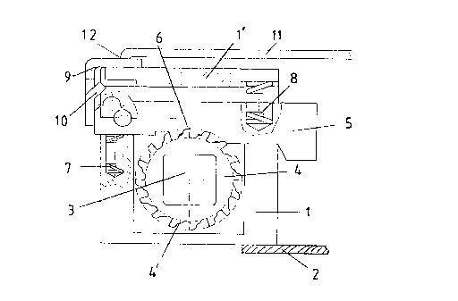
L'invention concerne un dispositif antiretour de chocs pour éviter le retour d'un premier élément de meuble soumis à la pression d'un ressort et monté inclinable sur un deuxième élément de meuble. L'angle d'inclinaison entre les deux éléments de meuble est réglable par blocage d'une broche filetée (3'), fixée sur un élément de meuble et montée, sans autoblocage, dans une pièce-écrou sur l'autre élément de meuble. La broche filetée ou la pièce-écrou sont réalisées sous forme de pièce montée rotative et sont disposées dans une enveloppe (2) sur un élément de meuble. Le blocage de la broche filetée (3, 3') se fait par application d'une force sur des mâchoires (16, 16') agissant sur elle, par l'intermédiaire d'un organe d'actionnement qui est situé dans ou sur l'enveloppe (2). En outre, la pièce montée rotative présente, au moins partiellement, une couronne dentée (4) ou un crochet de verrouillage externe avec lequel ou lesquels on peut mettre en prise un élément de verrouillage monté mobile sur l'enveloppe et présentant une butée adaptée. L'organe d'actionnement est, pour sa part, relié à un organe de déclenchement de verrouillage.


Abrégé anglais


The invention relates to a return-preventing device for preventing return kick
of a first spring-loaded furniture piece. This first furniture piece is
pivotingly mounted on a second furniture piece. The angle of inclination
between the two furniture pieces can be regulated by clamping a threaded
spindle (3'). Said threaded spindle is firmly fixed to one of the furniture
pieces. It is also mounted in a nut part on the other furniture piece, in such
a way that is not self-locking. The threaded spindle or the nut part are
configured as a rotating piece, and are fitted in a housing (2) on a furniture
piece. An actuating mechanism is used to apply force to clamping jaws (16,
16') which act on the threaded spindle, thus clamping said threaded spindle
(3, 3'). The actuating mechanism is stored in or on the housing (2).
Furthermore, the rotationally lodged piece at least partially has an external
toothed ring (4) or catch hook, with which a catch piece, having a suitable
abutment and mobilely stored on the housing, can be brought to mesh. The
actuating mechanism is connected with a catch release mechanism.

Revendications

Note : Les revendications sont présentées dans la langue officielle dans laquelle elles ont été soumises.


Claims
1. Restraint to prevent recoil of a spring-loaded first furniture part, in which this first
furniture apart is mounted to swivel on a second furniture part and the angle of inclination between the two
furniture parts can be adjusted by clamping a threaded spindle (3') which is fixed to one furniture part
and mounted free of self-restraint in a nut part on the other furniture part, in which the threaded spindle
(3') or the nut part is mounted to rotate and these functional parts are arranged in a housing (2) on one
furniture part, characterized in that the threaded spindle (3, 3') is clamped by exerting a force on the
clamping jaws (16, 16') acting on it via an operating mechanism, in which the operating mechanism is
mounted in or on the housing (2), that the rotatable mounted part has at least partially an outer gear rim
(4) or locking hooks with which a locking part having a matching stop mounted to move on the housing can be
engaged, that the operating mechanism is connected to a lock release device, in which, or assumption of
the clamping position of the operating mechanism, the lock release device brings the locking part into
blocking engagement with the gear rim (4) or locking hooks, and that means are present to keep the locking
part engaged with the gear rim (4) or the locking hooks after the force acting on the clamping jaws (16,
16') is removed and this engagement is released by changing the angle of inclination between the two
furniture parts.
2. Restraint according to Claim 1, characterized in that the furniture parts are the seat and
back rest of a chair, like an office swivel chair, and that the housing is a seat support (2) rigidly
connected to the seat.
3. Restraint according to Claim 2, characterized in that the threaded spindle (3, 3') is
guided on one end to run free of self-restraint in a nut part of the back rest support and that the clamping
jaws (16, 16'), the operating mechanism, the lock release device, the lock part and the gear rim (4) or
locking hooks are arranged on the other end of the threaded spindle in the seat support (2).
4. Restraint according to Claim 3, characterized in that the operating mechanism is a clamping
spindle (18) guided across the threaded spindle (3') through the seat support (2) and the clamping jaws
(16, 16') arranged in it, which is connected to an operating lever (14) mounted outside of the seat support

on it, by means of which a force directed across the axis of the threaded spindle can be applied to the
clamping jaws which clamp the threaded spindle.
5. Restraint according to Claim 3, characterized in that the locking part is a lever (5)
mounted to swivel on one end transversely to the gear rim (4) or locking hooks arranged laterally from this
in the seat support, in which spring devices (7) are present on its other end to secure this in a nonlocking
position and the lock release device introduces a clamping part that overcomes this spring force between
the lever and a stop part rigidly connected to the seat support.
6. Restraint according to Claim 5, characterized in that the clamping part is a projection
(10) of a clamping lever (9), which is mounted with one end on the stop part and the axis of rotation whereof
is arranged perpendicular to the axes of the threaded spindle (3') and the clamping spindle (18), in which
the clamping lever is connected on its other end to the lock release device and can be brought by this into
a clamping position.
7. Restraint according to Claim 6, characterized in that the lock release device is a rod (11)
guided with restricted movement one end in the operating lever (14), which is arranged essentially
transverse to the axis of the threaded spindle (3, 3') and on its other end has a hook (12) designed so that
this pulls clamping lever (9) into a clamped position during clamping operation of the operating lever
(14).
8. Restraint according to one of the Claims 3 to 5, characterized in that a compression spring
(17) is arranged under tension around threaded spindle (3, 3') between the nut part arranged on the bottom
end of the back rest support and the seat support, which forces these apart and seeks to impart a specific
direction of rotation to the threaded spindle so that the locking part with the gear rim (4) or locking
hooks can be brought into blocking engagement in this direction of rotation of the threaded spindle and
that a movement of the threaded spindle opposite this direction of rotation releases blocking.

Description

Note : Les descriptions sont présentées dans la langue officielle dans laquelle elles ont été soumises.

CA 02264645 1999-02-26DescriptionThe invention concerns a restraint to prevent recoil of a spring-loaded furniture part with thefeatures of the principal clause of Claim 1.This type of restraint to prevent recoil of a first spring—loaded furniture part, in which thisfirst fumiture part is mounted to pivot on a second furniture part and the angle of inclination betweenTranslated by:TCA—Trans|ation Co. of America10 West 37th StreetNew York, N.Y. 10018 (212) 563.7054CA 02264645 1999-02-26TCA Translation TCA Translationthe two fumiture pzuts czm be set by clamping a threaded spindle, which is fixed to one furniture part andmounted free of self—restraint in a nut part on the other fumiture part, in which the threaded spindle orthe nut part is a rotatable part and these functional parts are arranged in a housing on one furniture part,is known from German Patent Application No. 197 20 264.The task of the present invention is to devise an improved restraint with greater functionalreliability.This task is solved with the features mentioned in the characterizing part of Claim 1.Modifications and advantageous variants of the invention are contained in the additional claims.A restraint of the type mentioned at the outset is characterized according to the invention by thefact that clamping of the threaded spindle occurs by exerting a force on the clamping jaws acting on it viaan operating mechanism, in which the operating mechanism is mounted in or on the housing, that therotatable part has at least pzutially em outer gear rim or locking hooks with which a locking part mountedto move on the housing and having a matching stop can be engaged, that the operating mechanism is connectedto a lock release device, in which during assumption of the clamping position of the operating mechanismthe lock release device brings the locking part with the gear rim or locking hooks into blockingengagement, and that means are provided to keep the locking part engaged with the gear rim or locking hookafter the clamping force acting on the clamping jaws is released and this engagement is released bychanging the angle of inclination between the two furniture parts.A preferred variant of tlie invention also has one or more of the features that the furniture partsare the seat and back rest of a chair, like an office swivel chair, and that the housing is a seat supportrigidly connected to the seat, that the threaded spindle is guided on one end to run free of self-restraintin a nut part of the back rest support and the clamping jaws, the operating mechanism, the lock releasedevice, the locking part and the gear rim or locking hooks are arranged on the other end of the threadedspindle in the seat support, that the operating mechanism is a clamping spindle guided transversely to thethreaded spindle through the seat support and the clamping jaws arranged in it, which is connected to anoperating lever mounted outside of the support on it, by means of which a force directed transversely tothe axis of the threaded spindle can be applied to the clamping jaws and clamp them to the threaded spindle,that the locking part is a lever mounted to swivel on one end arranged transversely to the gear rim orlocking hooks laterally from them in the seat support, in which spring devices are present on its other endATranslated by:TCA-Translation Co. of America10 West 37th StreetNew York. N.Y. 10018 (212) 563-7054CA 02264645 1999-02-26TCA Translation TCA Translationto keep this in a non—locking position and the lock release device introduces a clamping part thatovercomes this spring force between the lever and a stop part rigidly connected to the seat support, thatthe clamping part is a projection of a clamping lever, which is mounted with one end on the stop part andwhose axis of rotation is arranged perpendicular to the axes of the threaded spindle and the clampingspindle, in which the clamping lever is connected on its other end to the lock release device and can bebrought by this into a clamping position, that the lock release device is a rod guided with limited movementon one end in the operating lever, which is arranged essentially transverse to the axis of the threadedspindle and on its other end has a hook for connection to the clamping lever, in which the motion limitationon the rod is designed so that this pulls the clamping lever into a clamping position during clampingactivation of the operating lever and/or that a compression spring is arranged under tension around thethreaded spindle between the nut part arranged on the bottom end of the back rest support and the seatsupport, to force these to push apart and to impart a specific direction of rotation to the threadedspindle, that the locking part with the gear rim or locking hooks are brought into blocking engagement inthis direction of rotation of the threaded spindle, and that a movement of the threaded spindle oppositethis direction of rotation releases blocking.The invention is further described below with reference to drawings as examples. In the drawings:Figure l shows a partial section through a restraint with a threaded spindle in the clampedposition;Figure 2 shows the restraint of Figure l in the free position;Figure 3 shows a top view ofthe restraint in the position of Figure 1;Figure 4 shows a top view of the restraint in the position of Figure 2.The restraint of Figures 1 — 4 is mounted in a housing 1, which is arranged on the bottom of a seatsupport 2 with a U-shaped cross section and encloses a threaded spindle 3, 3', which is mounted on one endto run free of self-restraint in a nut part (not shown) arranged on a back rest support of an office chairand is mounted to rotate on its other end but is fixed in housing 1. Because of mounting of one end ofthreaded spindle 3, 3' free of self—restraint in the nut part a length change between the back rest supportand the seat support 2 is possible, which results in a change in angle of inclination between the seat andback rest of the office chair. A compression spring 17 is arranged under tension between the seat support2 and the nut part on the back rest support connected to swivel on the end of the seat support, which actsTranslated by:TCA-Translation Co. of America10 West 37th StreetNew York, N.Y. 10018 (212) 553.7054CA 02264645 1999-02-26TCA Translation TCA Translation on an end of the back rest support situated beneath the connection. A clamping device for threaded spindle3, 3' is arranged in front of housing 1 in the seat support 2, which consists of two clamping jaws 16, 16',which are mounted on a clamping spindle 18 n10Lll)lC(l in the side wall 2' of seat support 2 and arrangedtransverse to the threaded spindle 3, 3'. A compression spring 1‘) acts between clamping jaws 16, 16', whichis to facilitate their loosening from the threaded spindle. The clamping spindle 18 lies on its other endwith a nut 20 behind the farther removed clamping jaw 16', in which this is clamped onto the threadedspindle 3' by the pressure of the nut. The clamping pressure is caused by a tensile force on the clampingspindle 18, which is applied in known fashion by an operating lever 14, in which this is forced through aneccentric surface 15 on the outer surface ofwall 2' of seat support 2 and secured. If clamping of threadedspindle 3' is released by operating the operating lever 14, the compression spring 17 would allow the backrest to spring forward on the top. To prevent this the restraint according to the invention is arrangedin housing 1.The restraint consists of a locking part, which is designed as a lever 5 or detent pawl amd has anotch that can be engaged with a gear rim 4 arranged around threaded spindle 3 and connected to rotate inunison with it, as shown in Figure l. The lever 5 is arranged here laterally chamfered transversely to theaxis of threaded spindle 3'. The lever is forced downward on its side facing the operating lever 14 by aspring 8 arrangusing top 1'. The teeth 4' of the gear rim are chamfered in the clockwise direction andengage in the matching notches 6 of lever 5, in which the threading of threaded spindle 3' is designed sothat the pressure of compression spring 17 ensures rigid wedging in this position between lever 5 and gearrim 4. Movement of the nut part on the other end of threaded spindle 3' causes rotation of the gear rimcotuiterclockwise so that the lever 5 can be released from the gear rim and reaches a position as shown inFigure 2 under the inlluence of a compression spring 7, which acts between the housing bottom 1 and the endof lever 5 facing away from operating lever 14. The end of lever 5 facing operating lever 14 has a downwarddirected chamfering 5' and then a stop end 5‘ in which, on loosening of lever 5, this slides with chamfcring5' over the side edge of housing bottom 1 , This arrangement achieves a situation in which the back rest canbe loosened only in a movement opposite the direction in which it was advanced.The blocking position of the restraint is achieved by operating operating lever 14. A rod 1 1 isarranged in this parallel to clamping spindle 18, which is guided over the housing 1 of the restraint. Therod 1 1 is guided with restricted movement by the stop device in a hole of the operating lever 18 and is4Translated by:TCA—TransIation Co. of America10 West 37th StreetNew York, N.Y. 10018 (212) 563.7054CA 02264645 1999-02-26....u.-..TCA Translation TCA Translationpulled outward over a specified path by pivoting the operating lever 18 in the clamping position for theclamping jaw 16, 16'. On its other end the rod 1 l is provided with a downward directed hook 12, whichengages in the free end of a clamping lever 9 mounted to pivot on housing 1, which is aligned in the clampingposition parallel to the threaded spindle 3, 3' and is arranged laterally on the housing with an axis ofrotation perpendicular to the threaded spindle. In the released position the clamping lever 9, as shownin Figure 4, protrudes obliquely from housing 1. If the rod l l is pulled by operating the operating lever14, the clamping lever 9 pivots into the position ough an inward directed protrusion 10 it then presses onthe end of lever 5 facing away from operating lever 14 and moves this to the right and downward against theforce ofcompression spring 7, as is apparent on comparison of Figure 2 with Figure 1. The teeth 4' of thegear rim 4 of threaded spindle 3' then engage in the notches 6 of lever 5 and the threaded spindle, asdescribed above, is blocked by the force of compression spring 17.SummaryRestraint to prevent recoil ofa spring—loaded first furniture part, in which this first furniturepart is mounted to pivot on a second f umiture part and the angle of inclination between the two furnitureparts can be adjusted by clamping a threaded spindle, which is mounted fixed on one ftuniture part and freeof self-restraint on a nut part on the other furniture part, in which the threaded spindle or the nut partis a rotatable part and these functional parts are arranged in a housing on a furniture part in whichclamping of the threaded spindle occurs by exerting a force on the clamping jaws acting on these via anoperating mechanism, in which the operating mechanism is mounted in or on the housing, in which therotatable part has at least partially an outer gear rim or locking hooks with which a locking part mountedto move on the housing and having a matching step can be engaged, in which the operating mechanism is alsoconnected with a lock release device, in which, on assumption of the clamping position of the operatingmechanism, the lock release device brings the lock part into blocking engagement with the gear rim orlocking hooks and in which, finally, means are provided to keep the locking part engaged with the gear rimor locking books after the clamping force acting on the clzunping jaws is removed and this engagement isreleased by changing the angle of inclination between the two furniture parts.Translated by:TCA—TransIation Co. of America10 West 37th StreetNew York, N.Y. 10018 (212) 563-7054
Dessin représentatif
Une figure unique qui représente un dessin illustrant l'invention.
États administratifs

2024-08-01 : Dans le cadre de la transition vers les Brevets de nouvelle génération (BNG), la base de données sur les brevets canadiens (BDBC) contient désormais un Historique d'événement plus détaillé, qui reproduit le Journal des événements de notre nouvelle solution interne.

Veuillez noter que les événements débutant par « Inactive : » se réfèrent à des événements qui ne sont plus utilisés dans notre nouvelle solution interne.

Pour une meilleure compréhension de l'état de la demande ou brevet qui figure sur cette page, la rubrique Mise en garde , et les descriptions de Brevet , Historique d'événement , Taxes périodiques et Historique des paiements devraient être consultées.

Historique d'événement

Description Date
Inactive : Regroupement d'agents 2013-08-14
Le délai pour l'annulation est expiré 2002-07-02
Demande non rétablie avant l'échéance 2002-07-02
Inactive : Regroupement d'agents 2002-05-09
Réputée abandonnée - omission de répondre à un avis sur les taxes pour le maintien en état 2001-07-03
Lettre envoyée 1999-05-27
Inactive : Transfert individuel 1999-04-26
Inactive : CIB attribuée 1999-04-26
Inactive : CIB en 1re position 1999-04-26
Inactive : Lettre de courtoisie - Preuve 1999-04-20
Inactive : Notice - Entrée phase nat. - Pas de RE 1999-04-14
Demande reçue - PCT 1999-04-09
Demande publiée (accessible au public) 1999-01-21

Historique d'abandonnement

Date d'abandonnement Raison Date de rétablissement
2001-07-03

Taxes périodiques

Le dernier paiement a été reçu le 1999-02-26

Avis : Si le paiement en totalité n'a pas été reçu au plus tard à la date indiquée, une taxe supplémentaire peut être imposée, soit une des taxes suivantes :

  • taxe de rétablissement ;
  • taxe pour paiement en souffrance ; ou
  • taxe additionnelle pour le renversement d'une péremption réputée.

Veuillez vous référer à la page web des taxes sur les brevets de l'OPIC pour voir tous les montants actuels des taxes.

Historique des taxes

Type de taxes Anniversaire Échéance Date payée
TM (demande, 2e anniv.) - générale 02 2000-07-03 1999-02-26
Taxe nationale de base - générale 1999-02-26
Enregistrement d'un document 1999-04-26
Titulaires au dossier

Les titulaires actuels et antérieures au dossier sont affichés en ordre alphabétique.

Titulaires actuels au dossier
SIFA SITZFABRIK GMBH
Titulaires antérieures au dossier
REINHARD GEBHARD
Les propriétaires antérieurs qui ne figurent pas dans la liste des « Propriétaires au dossier » apparaîtront dans d'autres documents au dossier.
Documents

Pour visionner les fichiers sélectionnés, entrer le code reCAPTCHA :


Pour visualiser une image, cliquer sur un lien dans la colonne description du document. Pour télécharger l'image (les images), cliquer l'une ou plusieurs cases à cocher dans la première colonne et ensuite cliquer sur le bouton "Télécharger sélection en format PDF (archive Zip)" ou le bouton "Télécharger sélection (en un fichier PDF fusionné)".

Liste des documents de brevet publiés et non publiés sur la BDBC .

Si vous avez des difficultés à accéder au contenu, veuillez communiquer avec le Centre de services à la clientèle au 1-866-997-1936, ou envoyer un courriel au Centre de service à la clientèle de l'OPIC.


Description du
Document 
Date
(aaaa-mm-jj) 
Nombre de pages   Taille de l'image (Ko) 
Abrégé 1999-02-26 1 58
Description 1999-02-26 5 267
Revendications 1999-02-26 2 104
Dessins 1999-02-26 3 72
Page couverture 1999-04-27 2 70
Dessin représentatif 1999-04-27 1 11
Avis d'entree dans la phase nationale 1999-04-14 1 193
Courtoisie - Certificat d'enregistrement (document(s) connexe(s)) 1999-05-27 1 116
Courtoisie - Lettre d'abandon (taxe de maintien en état) 2001-07-31 1 182
PCT 1999-02-26 3 142
Correspondance 1999-04-20 1 31