Note : Les descriptions sont présentées dans la langue officielle dans laquelle elles ont été soumises.
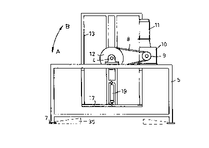
101520W0 98/1 1008CA 02265778 l999-03- 10PCT/AU97/00592-1-APPARATUS FOR INVERTING CONTAINER MEANSFIELD OF THE INVENTION.This invention is concerned generally with emptying containers andparticularly with placing containers in a state of readiness for emptying.This invention has been devised with containers in mind which include apallet or base with four upstanding interlocked sides. Whilst the inventionhas been devised with the above form of container particularly in mind it isnot limited to such containers.BACKGROUND TO THE INVENTION.When containers have to be emptied the methods adopted depend to alarge extent on the contents of the container. in the case of flowablematerial, such as granules, gravitational discharge it the preferred option.To facilitate this form of emptying a container attempts have been made todevelop containers which have a bottom discharge means. For a numberof reasons containers with a bottom discharge incorporated in a base orpallet forming part of the container have not found favour with users.An alternative is to tilt the container, usually in a tilting device on which thecontainer is mounted, to the extent required to cause the contents to flowfrom the container over a top edge of one of the container sides. . Toprovide a generally uniform rate of discharge, which is the normalrequirement, the tilt of the container has to be continually adjusted. Thisdischarge method is labour and/or time intensive and is therefore notfavoured.101520W0 98/1 1008CA 02265778 l999-03- 10PCT/AU97/00592-2-Another discharge method is to mount a hood with a discharge openingfitted with a flow controlling device to the open top of the container andthen support the container in an inverted condition to allow material in thecontainer to gravity discharge through the discharge opening of the hood.The challenge with this method is how to invert the container and supportit in the inverted manner in the most efficient and economical manner.The present invention addresses this challenge.GENERAL DESCRIPTION OF THE INVENTION.Generally, the invention can be said to provide an inverting apparatus fora container means, said inverter includes a cradle pivotally mounted on aframe and pivotally movable by cradle moving means, said cradle has anopen side to allow a container means to be entered into a receiving zoneof said cradle, said receiving zone is defined by two spaced apartoppositely disposed cradle sides, a cradle back opposite said open sideand two cradle ends at least one of which is linearly movable towards andaway from the other cradle end to adopt retracted and extended conditionsrespectively.BRIEF DESCRIPTION OF THE DRAWINGS.Fig.1 is a front view of a container inverter according to the presentinvention, when in a closed container retaining condition,Fig.2 is a side view of the inverter of Fig.1,Fig.3 is a front view of the inverter of Fig.1 in an open container loadingand unloading condition,Fig.4 is a side view of the inverter of Fig.3,10152025W0 98/1 1008CA 02265778 l999-03- 10PCTIAU97/00592- 3 -Fig.5 is a front view similar to Fig.3 with a container loaded into the inverterand separated from a container hood which is supported in the inverter,Fig.6 is a view similar to Fig.1 following elevation of the container shownin Fig.5 and coupling to the hood in the inverter, and as it would appear ifa container/hood assembly had been loaded into the inverter and elevated,Fig.7 is a schematic perspective view of a container of the type suitable forloading into the inverter,Fig.8 is a side elevation of a hood adapted for automatic coupling to acontainer as shown in Fig.7,Fig.9 is a front view of the hood of Fig.8 showing container coupling meansin a release condition,Fig.1O is an enlarged fragmentary view of a hood as shown in Figs.8 and9 supported in the inverter ready for coupling to a container andFig.11 is a view similar to Fig.1O showing a container coupled to the hood.DETAILED DESCRIPTION OF THE DRAWlNGS.in Fig.1 the tilter assembly 1 includes a cradle 2 supported through stubaxles 3 in bearings 4 on frames 5 and 6 with floor engaging feet 7. Asillustrated there is a chain 8 connecting a driving sprocket 9 of a power unit10 driven by an electric motor 11, to a sprocket 12 fixed to one of the stubaxles 3. By suitable control means the power unit 10 can be used to rotatethe cradle 2 through 180 degrees in the direction of arrow A from theposition illustrated in Fig.2 and then return the cradle in the direction of thearrow B to the Figs.1 and 2 condition.The cradle 2 includes a frame made up longitudinal members 13 andlateral members 14 providing a channel shaped trough with two parallel10152025W0 98/1 1008CA 02265778 l999-03- 10PCT/AU97/00592- 4 -sides and a channel base opposite the open side of the channel, a fixedend 15 and a movable end assembly 16. The end assembly 16 includesa foot plate 17 mounted on the frame members 13 in a manner allowingthe foot plate 17 to be moved linearly towards and away from the cradleend 15 between a lowered condition shown in Figs. 3 and 4 and a raisedcondition as shown in Figs.1 and 2. The connection between the footplate 17 to the cradle frame members 13 can be any one of a number ofsuitable telescopic type connections. An example would be to havewheels on the uprights 18 of the foot plate 17 engaged in tracks in theframe members 13.Hydraulic piston and cylinder assemblies 19 (see Fig.2) are provided onopposite sides of the cradle to move the foot plate 17 relative to the cradleframe members 13.The tilter has been devised with a specific form of container assembly inmind. That container 20 of the assembly is shown in schematic form inFig.7 and a hood 21 for mounting on the container 20 can be of the simpleform shown in Figs.5 and 6, where the hood is clamped in a suitablemanner to the container 20, or it can be of a self latching type, as shownin Figs.8 and 9. The hood 21 in both forms includes a discharge funnel 22disposed within an arrangement of ground engaging legs 23 betweenwhich tubular members 24 are provided to receive fork lift truck tines.In the hood 21 illustrated in Figs. 8 and 9 the fork lift tine engagingmembers 24 are coupled through posts 25 to tie members members 26connecting the hood legs 23 and are biassed into engagement with the tiemembers 26 by springs 27. Post stop ends 28 are connected through10152025W0 98/1 1008CA 02265778 l999-03- 10PCT/AU97/00592-5-lever arms 29, mounted on shafts 30, to pivotally mounted arms 31provided with hook ends 32. The hooked ends 32 are adapted to engagecoâoperating portions of the container 20 at the open top thereof. In onearrangement the hook ends 32 engaged under upper bars 33 of the framesof the container sides It follows that by raising the members 24 relativeto the frame of the hood 21 by means of fork lift truck tines (see Fig.9) thehooked ends 32 of the arms 31 would be moved to a container releasecondition shown in Fig. 9 and when the hood was lowered onto acontainer and the fork lift tines were removed from the members 24 thesprings 27 would cause the hook ends 32 to move to container engagingpositions. This arrangement is fully disclosed in the patent applicationnumber 32462/97.In a first mode of use of the inverter, a simple hood 21 as shown in Figs.5and 6 or the self latching type of Figs.8 and 9 would be fitted to the opentop of a container and the assembly would be put into the cradle throughan open side thereof to rest on a lowered foot plate 17. This would beachieved by engaging the fork lift tines with the pallet type base 34 of thecontainer 20.The foot plate 17 would then be raised by the piston and cylinder units 19to secure the container/hood assembly between the tilter ends 15 and 16so substantially preventing endwise movement of the container/hoodassembly during the inversion thereof. Suitable retaining means wouldnormally be provided to retain the tilter foot plate 17 in the retractedcondition so as to not rely on the lifting and lowering means 19 to retain thefoot plate in the retracted condition during cradle inversion.101520W0 98/1 1008CA 02265778 l999-03- 10PCT/AU97/00592-5-After inversion of the container/hood assembly (movement arrow A), thecontainer assembly would be in the orientation of Fig.10. The foot plate17 would be moved (raised) to an extended condition to allow thecontainer/hood assembly to be freely removed from the cradle by a fork lifttruck with the tines engaged in the hood members 24.Thereafter the cradle 2 would be returned to its original position (movementarrow B), ready for another inversion cycle.As will be understood the foot plate 17 can be provided at both ends of thecradle and the cradle could be associated with a ramped floor zone, seethe dotted outline of ramps indicated 35 in Figs.1 and 2. With such anarrangement the hood 21 would be provided with a modified groundengaging portion complete with fork lift truck tine sleeves shown in brokenlines in Fig.5 and indicated 24a. Using a ramp as illustrated thecontainer/hood assembly can be handled by a hand truck making itunnecessary to use a fork lift truck to load the container assembly into thecradle and remove it from the cradle.In a variation of the foregoing, the hood 21 could be retained in the cradle2 and would be automatically coupled to a container 20 and uncoupledtherefrom, thereby avoiding the need to perform those operationsexternally of the tilter by means of a fork lift truck and thereby save timeand effort.The hood 21 for such use would be of the type shown in Figs.8 and 9.There would be a pair of spigots 36 fixed to the bottom of the cradlechannel aligned with the members 24 of the hood 2 and lying adjacent the10152025W0 98/1 1008CA 02265778 l999-03- 10PCT/AU97/00592- 7 -lower inner faces of the members 24 when in the position shown in Fig.11with the feet 37 of the hood legs 23 engaged with the cradle end 15.In an initial hood set-up operation the hood 21 would be placed in thecradle upper zone, as shown in Fig.12 with the spigots 36 entered into theleading ends of the tine engaged members 24, initially in approximately amid-height position within the members 24. As will be understood thesprings 27 will be compressed due to the down load exerted by the weightof the hood as it is lifted by tines in the members 24. The linkages will beoperated so the hooks 32 will adopt the illustrated release condition. Thehood 21 would then be lowered until the hook ends 32 of the members 31bear on bars 38 fixed to the cradle members 13. The cradle is supportedin this manner after the removal of the fork lift tines from the members 24.When the hood is so supported the spigots 36 lie closely adjacent theupper innerfaces of the members 24, see Fig.12.A container would then be placed in the lower zone of the cradle on alowered foot plate 17. The foot plate 17 would then be raised and thecontainer 20 would be raised. Because the hooks 32 are âopenâ the topof the container 20 can come into contact with the lower end of the hoodframe. As the container 20 is raised further the hood 21 will be raisedrelative to the spigots 36, which were holding the members 24 raised andthe linkages in a condition in which the hooks maintained the âopenâcondition. The raising of the hood relative to the spigots allows the springs27 to move the linkages with the result that the hooked ends 32 moveinwardly and engage under the top bars 33 of the frames of the sides of thecontainer 20, thereby locking the hood to the container. When the feet 37of the hood legs engage the cradle end 15 the spigots 36 will lie adjacent101520W0 98/1 1008CA 02265778 l999-03- 10PCT/AU97/00592-3-the lower inner faces of the members 24, see Fig.11.The inverter is pivoted to invert the container/hood assembly. Theassembly is removed from the inverted cradle after release by the footplate 17, or a counterpart foot plate at the end 15 of the cradle, by meansof a fork lift truck engaged with the members 24, as before described.Alternatively, a hand truck can be used to remove the assembly with thehand truck engaging the modified foot section of the hood, as beforedescribed.After emptying the container/hood assembly would be replaced in thecradle, using a form lift truck or hand truck, the assembly would be securedin the cradle, as before described, and inverted to the Fig.6 configuration.After inversion of the cradle the foot plate 17 would be released andlowered. The lowering of the container/hood assembly brings the upperinner faces of the members 24 into engagement with the spigots 36, thelinkage of the hood would be actuated to release the hooked ends 32 (seeFig.12) from the container. Further lowering of the container 20 will resultin the Fig.5 configuration allowing the empty container to be removed fromthe cradle by a fork lift truck or a hand truck. A full container would beplaced on the foot plate 17 and the cycle is repeated.As will be understood this arrangement avoids the need to mount anddismount the hood from a container externally of the cradle therebyproviding a substantial saving in time and effort and substantially speedsup the handling of containers.