Note : Les descriptions sont présentées dans la langue officielle dans laquelle elles ont été soumises.
CA 02266106 2001-06-08
29318-22
1
RAIL VEHICLE WITH A VERTICAL SUPPORT ACTUATOR
The invention relates to a rail vehicle having a
support actuator compri_:>ing two control elements capable of
linear axial adjustment: relative to each other, the support
actuator being mounted between a vehicle body and the frame of
a running gear located under the vehicle body and thereby
acting as a support spring.
The provision of spring elements arranged
mechanically parallel t:o each other or in series to support a
vehicle body on a running gear located thereunder is generally
known in the context of rail vehicles. If one of the spring
elements fails, the eff=ect of the associated second spring
element is maintained. In parallel arrangements, however, this
involves a considerable: reduction of supporting force, while a
series arrangement results in a great overall length in the
effective direction.
The invention is based on providing a rail vehicle as
described in the opening paragraph wherein one spring only is
effective in the usua:L operating conditions while maintaining a
compact construction.
According to the invention there is provided a rail
vehicle having a support actuator comprising two control
elements capable of linear axial adjustment relative to each
other, the support actuator being mounted between a vehicle
body and a frame of a running gear located under the vehicle
body and thereby acting as a support spring wherein an
emergency spring having two ends is coaxially arranged around
the support actuator, one end of the emergency spring and one
end of the support actuator are mounted on the running gear
CA 02266106 2001-06-08
29318-22
1a
frame, a supporting stop is faxed to the support actuator in
the area of its other end, the supporting stop is clear of the
other end of the emergency spring while the support actuator is
extended during operats.on, and the supporting stop rests on the
other end of the emergency spring when the support actuator
fails.
In constructing a rail vehicle according to the
invention, the emergency spring, 'which is parallel in action to
the support actuator in operative use, is loaded only when the
support actuator at least largely loses its resilient
supporting function. C>nly then does the stop connected to the
end of the support actuator, which is adjustable relative to
the emergency spring, come into contact with the adjacent end
face of the emergency :>pring. In the usual operating
conditions, the action of the support actuator is therefore not
influenced in any way. If, on the other
CA 02266106 1999-03-18
- -2-
hand, the support actuator fails, the emergency spring absorbs
the full load of the vehicle body, which merely drops to a lower
level. The emergency spring can thus be matched to the actual
body load by mechanical prestress~ing and limiting its stroke,
thus ensuring the clearance between emergency spring and stop
which is required for the normal working stroke. The actuator is
in particular a hydropneumatically controlled cylinder with cor-
responding resilience, the force or extension to be applied being
controlled in dependence on operating conditions. The cylinder
housing of the actuator is preferably rigidly fixed to the
running gear frame, on which one e:nd of the emergency spring is
seated as well. The stop associated with the piston rod of the
actuator can be attached directly i=o the piston rod. Preferably,
however, it is connected to the free end of the piston rod by way
of a flexible joint designed as a ball joint. In this way, the
stop can be firmly attached to a plate of a sliding adapter, the
counter-plate of which is firmly attached to the floor of the
vehicle body while being freely adjustable in one plane relative
thereto. The sliding adapter may i.n particular be designed as a
ball table. It is only adjustable parallel to the plane of the
floor of the vehicle body.
The emergency spring is preferably cylindrical in design and co-
axial with the cylinder housing. 'the stop, too, is cylindrical
and matched in diameter, so that it. comes to rest without tilting
on the adjacent end face of the emergency spring during any fail-
ure of the actuator and is capable: of compressing the emergency
spring while clearing the external surface of the cylinder hous-
ing.
To limit the stroke of the mechanically prestressed emergency
spring, a limiting stop consisting of several parts, if required,
is provided, which extends in front of the end of the emergency
spring facing the stop, while its other end is attached to the
running gear frame. In this arrangement, lateral buckling is
prevented by the fact that the emergency spring is guided both
by the cylinder housing of the support actuator and by those
CA 02266106 2001-06-08
29318-22
3
parts of the supporting stop which are located in the outer
area of the emergency ~;pring.
The invention is described in detail below with
reference to some sketches of an embodiment, of which
Figure 1 is a. perspective view of a running gear with
equipment to connect it to a superimposed vehicle body;
Figure 2 is a. side view of connecting equipment with
associated emergency s~n-ing; and
Figure 3 is a section a:Long line I-I in Figure 2.
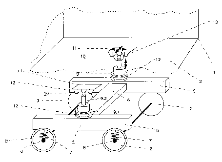
The body 1 of a vehicle, in particular a rail
vehicle, under the floor panel 2 of which a running gear is
located, is indicated c.i.agramrnatica.lly. The running gear 4
consists of at least ore axle or two wheels 3, in the
illustrated embodiment= two parallel axles or four wheels 3.
l.~ The wheels 3 are designed to run on rails. The running gear
frame 4 comprising lorrgi.tudinal members 5 extending in the
direction of travel of the running gear and linked to each
other by at least one crossmember 6 is supported on wheel
bearing elements 8 of the wheels 3 by means of primary springs
7, thus providing a stable coupling arrangement for the wheels
3. Approximately midway between two wheels arranged in tandem
in the direction of travel, each .Longitudinal member 5 supports
connecting equipment 9, 10, 11 at :right angles to the plane
formed by these longitudinal members 5, whereby the vehicle
2.'~ body 1 with its floor panel 2 is supported on the running gear.
Th~~ connecting equipment comprises an actuator 9, a
flexible joi:zt 10 tilt:able in any direction and a sliding joint
11; all thes~= parts ar_e arranged mechanically in series in the
effective direction of: the actuator_ 9. The actuators 9, which
CA 02266106 2001-06-08
29318-22
4
may in particular be designed as hydraulic cylinders, comprise
two control elements 9.1 and 9.2 capable of linear axial
adjustment relative to each other only. The flexible joints 10
may be designed as un:ivE:rsal or ball joints, rubber-elastic
joints or else as spring :bars for swivel movements with limited
amplitude in all directions in one plane. The sliding joint 11
only has translational degrees of freedom in one plane lying
parallel to the floor panel 2 of the vehicle body 1. The
directional travel of this sliding joint in one plane i.s
limited to preset values. The allocation of the individual
elements 9, 10, 11 of t:he connecting equipment has the result
that only the actuator is capable of compensating for spacing
differences between the. running gear 4 and vehicle body l, that
the flexible joint 10 ~.:~ capable only of compensating for
tilting movements in a nondirectional way and that that the
sliding joint 11 is capable only of compensating for movements
at right angles to the direction of adjustment or the axis 15
of the actuator 9. Provided that the two end elements are
fixed to the running gear 4 on the one hand and to the vehicle
body 1 on the other hand, the sequence in which the elements 9,
10, 11 are assembled does not affect the principle.
In the illustrated embodiment, the cylinder housing
9.1 of, for instance, hydraulic actuators 9 with vertical axes
15 are rigidly mounted on the longitudinal members 5. The
other contrcl element ~~.2 of the actuator 9 is a piston rod of
the cylinder piston, wh_Lch is guided in the control element 9.1
for linear rr.ovement along the axis 15 only, the free end of the
control elerr.ent 9.2 be__ng rigidly connected to the first swivel
element 10.1 of the flexible joint 10, while the second swivel
element 10.2 is rigidly connected to the primary sliding
element 11.1 of the sluding joint 11. The flexible joint 10
designed as a ball joint permits only tilting movements between
CA 02266106 2001-06-08
29318-22
the planes formed by the longitudinal members 5 and the floor
panel 2. To compensate for lateral movements between the
vehicle components l, ::, 4 or for the lateral displacement
resulting from the twist: of the two planes, the sliding joint
5 11 is provided, .its primary s=Liding element 11.1 being fixed to
the second swive:L element 10.2 of the flexible joint 10, while
the secondary sliding e~l_ement 11.'? is fixed to the floor panel
2 of the vehicle body 1.
In this type of construction, the actuator 9 can
replace spring elemeni~s acting as secondary suspension. For
this purpose, it is in particular designed as a
hydropneumatically operated cylinder and does therefore not
only compensate for variations in the vertical distance between
vehicle body and running gear frame, but it can also offer the
1.~ elastic characteristics of helica:L springs, air springs or the
like. The spring characaeristics can be controlled in
accordance with requiremenu . The coupling between vehicle
body and the running dear for the support of axial and
transverse forces may be of a conventional nature, for instance
by means of link, pivot or lemniscate coupling elements or by
elastic puffer or spring elements.
Tha connecting equipment 9, 10, 11 can, of course
alternatively be cambered between vehicle body 1 and running
gear 4.
2.'~ In order to operate a rail vehicle of this design
with adequate comfort and safety following a failure of the
support actuator 9, a passive emergency spring 12 coaxial with
the support actuator 9 i.s provided. In the same way as the
CA 02266106 2001-06-08
29318-22
5a
cylinder housing 9.1 of the support actuator 9, the axial end
of the emergency spring 12 is seated on a longitudinal member 5
of the running gear 4. T:he opposite end 12.1 of the emergency
spring 12, which face~~ the vehicle body l, is arranged with
axial spacing opposite an annular supporting stop 13, which is
likewise coaxial with the support actuator 9, its ring end face
13.1 having the same c:~i.ameter as the emergency spring 12. The
other end of the annular supporting stop 13 is rigidly
connected to the primary sliding element 11.1 of the sliding
joint 11. As the primary sliding element 11.1 does not move
laterally relative to t:he longitudinal axis 15 of the support
actuator, its axial co--ordination with the emergency spring 12
is always maintained.
The axial free distance between the upper end 12.1 of
the emergency spring :L~'. and the adjacent free ring end face of
the annular supporting stop 13 is calculated to ensure that
there is no contact between the supporting stop 13 and the
emergency spring 12 during the stroke of the support actuator
in the usual operating
CA 02266106 1999-03-18
-6-
conditions. Very high loadings or t:he failure of the support act-
uator, however, cause the supporting stop 13 to drop axially onto
the free end of the emergency spring 12 under the guidance of the
support actuator 9. The emergency spring is designed to absorb
the static and dynamic forces generated between running gear 4
and vehicle body 1 during normal operation, the stroke of the
actuator 9 not being reduced to it:; lower limit under these con-
ditions. When the vehicle body 1 is only lowered, the suspension
behaviour of the arrangement is maintained. The internal diameter
of the annular supporting stop 13 is greater than the external
diameter of the cylinder housing '9.1, in order to make optimum
use of the available suspension gravel by overtravel. The sup-
porting stop, which is open towarda the emergency spring 12, can
thus axially overlap the barrel oi: the cylinder 9.
In order to keep its axial dimension to a minimum, the emergency
spring 12 is mechanically prestres;sed in the axial direction. To
achieve this, its free end 12.1 f: acing the supporting stop I3
rests against at least one limiting stop 14 fixed to the running
gear frame 5. The stop 14 consists of two parts and is located
on half shells 14.1 fixed diametrically to the longitudinal memb-
er 5 in the area of the external surface of the emergency spring
12. In the form of ring surface sections, the stops 14 horizont-
ally cover the outer edge of the free upper end 12.1 of the em-
ergency spring 12 in the radial direction. In the circumferential
direction, there is a free area between the two limiting stops
14, in which the supporting stop 13 can be seated on diametrical-
ly opposite sections over the whole radial dimension of the
emergency spring 12. The clearance between the mounting point of
the emergency spring 12 on the running gear frame 4 and the lim-
iting stop 14 is smaller than the axial dimension of the relaxed
emergency spring. By selecting the distance between longitudinal
member 5 and limiting stop 14, the prestressing of the emergency
spring 12 can be matched to the prevailing operating conditions.