Sélection de la langue

Search

Sommaire du brevet 2266548 

Énoncé de désistement de responsabilité concernant l'information provenant de tiers

Une partie des informations de ce site Web a été fournie par des sources externes. Le gouvernement du Canada n'assume aucune responsabilité concernant la précision, l'actualité ou la fiabilité des informations fournies par les sources externes. Les utilisateurs qui désirent employer cette information devraient consulter directement la source des informations. Le contenu fourni par les sources externes n'est pas assujetti aux exigences sur les langues officielles, la protection des renseignements personnels et l'accessibilité.

Disponibilité de l'Abrégé et des Revendications

L'apparition de différences dans le texte et l'image des Revendications et de l'Abrégé dépend du moment auquel le document est publié. Les textes des Revendications et de l'Abrégé sont affichés :

  • lorsque la demande peut être examinée par le public;
  • lorsque le brevet est émis (délivrance).
(12) Brevet: (11) CA 2266548
(54) Titre français: SCIE MECANIQUE
(54) Titre anglais: SAWING MACHINE
Statut: Périmé et au-delà du délai pour l’annulation
Données bibliographiques
(51) Classification internationale des brevets (CIB):
  • B23D 45/18 (2006.01)
  • B27B 11/00 (2006.01)
(72) Inventeurs :
  • NIEMELA, AHTI (Finlande)
(73) Titulaires :
  • AHTI NIEMELA
(71) Demandeurs :
  • AHTI NIEMELA (Finlande)
(74) Agent: SMART & BIGGAR LP
(74) Co-agent:
(45) Délivré: 2005-04-26
(86) Date de dépôt PCT: 1997-09-09
(87) Mise à la disponibilité du public: 1998-04-02
Requête d'examen: 2002-08-22
Licence disponible: S.O.
Cédé au domaine public: S.O.
(25) Langue des documents déposés: Anglais

Traité de coopération en matière de brevets (PCT): Oui
(86) Numéro de la demande PCT: PCT/FI1997/000536
(87) Numéro de publication internationale PCT: FI1997000536
(85) Entrée nationale: 1999-03-23

(30) Données de priorité de la demande:
Numéro de la demande Pays / territoire Date
963788 (Finlande) 1996-09-23
965023 (Finlande) 1996-12-13

Abrégés

Abrégé français

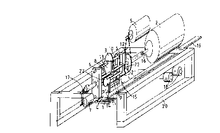
La présente invention concerne un équipement de scierie destiné à scier à cotes fixes un objet long. Cet équipement de scierie est constitué d'un chariot (1) servant à faire avancer l'objet à scier et de lames (3, 4) mises en rotation par un premier groupe moteur (2) de façon à couper l'objet. L'équipement de scierie comporte, d'une part un châssis rotatif (6) mis en rotation par un deuxième groupe moteur (5), les lames (3, 4) étant supportées par le châssis rotatif considéré, et d'autre part un troisième groupe moteur (7) et des barres de guidage (8, 9) montés sur le châssis rotatif de façon à permettre au troisième groupe moteur d'animer les lames d'un mouvement d'aller et retour avant-arrière, le long des barres de guidage dans le sens de la longueur de l'objet à scier.


Abrégé anglais


A sawing device for sawing a long object to a fixed size, said sawing device
comprising a conveyor (1) for conveying the object
to be sawn and blades (3, 4) rotated by a first power unit (2) for cutting the
object. The sawing device comprises a rotatable frame (6)
rotated by a second power unit (5), the blades (3, 4) bein supported by said
rotatable frame, a third power unit (7) and guide bars (8, 9) in
the rotatable frame to allow the blades (3, 4) to be moved back and forth by
the third power unit along the guide bars in the longitudinal
direction of the object to be sawn.

Revendications

Note : Les revendications sont présentées dans la langue officielle dans laquelle elles ont été soumises.


6
CLAIMS
1. Sawing device for sawing a long object to
a fixed size, said sawing device comprising
- a conveyor (1) for conveying the object to
be sawn
- blades (3, 4) rotated by a first power unit
(2) for cutting the object and
- a rotatable frame (6) rotated by a second
power unit (5), the blades (3, 4) being supported by
said rotatable frame,
characterized in that
- the sawing device comprises a third power
unit (7) and
- the rotatable frame (6) comprises guide
bars (8, 9), the blades (3, 4) being supported by
blade holders (13, 14) movable along the guide bars
(8, 9),
so that when sawing the object the third
power unit mowes one of the blade holders and blades
forward at the speed of the object when at the same
time the other blade holder and the blade is mowed
backward to the starting position of a new sawing op-
eration.
2. Sawing device as defined in claim 1,
characterized in that the rotatable frame (6)
comprises blade axles (10, 11) disposed at the same
distance from the axle (12) of the rotatable frame and
parallel to it.
3. Sawing device as defined in claim 1,
characterized in that the blade holders (13,
14) are connected to a motion chain (15) which can be
moved back and forth.
4. Sawing device as defined in any one of
claims 1 - 3, characterized in that the

7
first, second and third power units (2, 5, 7) are cou-
pled via concentric axles (16, 12, 17) to the ro-
tatable frame (6).
5. Sawing device as defined in any one of
claims 1 - 4, characterized in that the third
power unit (7) is arranged to move the blades (3, 4)
at the velocity of motion of the object to be sawn and
in the direction of motion of the conveyor (1).
6. Sawing device as defined in any one of
claims 1 - 5, characterized in that it has at
least three blades supported by the rotatable frame
and movable back and forth in the longitudinal direc-
tion of the object to be sawn.
7. Sawing device as defined in any one of
claims 1 - 6, characterized in that the
blades (3, 4) are discoid circular-saw blades.
8. Sawing device as defined in any one of
claims 1 - 7, characterized in that the ob-
ject to be sawn is timber.

Description

Note : Les descriptions sont présentées dans la langue officielle dans laquelle elles ont été soumises.


CA 02266548 1999-03-23
WO 98/13165 PCT/FI97/00536
1
SAWTNG MACHINE
The present invention relates to a sawing de-
vice as defined in the preamble of claim 1.
Traditionally, long timber is sawn to a fixed
size by moving the timber against a stopper adjusted
to a suitable position with respect to the saw blade
used, so that when the timber is in position the saw
blade cuts a piece of desired fixed length off the
timber. The fixed-length piece is then removed and the
timber to be sawn is further advanced longitudinally
against the stopper. In this manner, sawing is contin-
ued in stages by moving the timber and then sawing it.
The main problem with present sawing equip
ment and methods used to cut timber to a fixed size is
that they are slow, which is due to the intermittent
nature of the sawing. As the cutting operation itself
is a relatively fast action, most of the time is con-
sumed while the saw blade is waiting for the timber to
be moved into the sawing position against the stopper.
The slowness of sawing is a particularly bad problem
in industries where there is a need for large quanti-
ties of relatively short fixed-length timber pieces,
for example in furniture industry, prefabricated buil-
ding industry and parquet industry.
The object of the invention is to eliminate
the drawbacks referred to above. A specific object of
the invention is to produce a new type of sawing devi
ce that enables long timber to be accurately cut into
fixed-length pieces in a continuous process as fast as
possible.
As for the features characteristic of the sa-
wing device of the invention, reference is made to the
claims.
The sawing device of the invention comprises
a conveyor for conveying the timber to be sawn and
blades for cutting the timber at desired points, said

CA 02266548 1999-03-23
WO 98/I3165 PCT/FI97/00536
2
blades being rotated by a first power unit and dis-
posed in a transverse position relative to the
lengthways direction of the timber to be sawn. Accor-
ding to the invention, the sawing device comprises a
rotatable frame rotated by a second power unit and
supporting the blades, of which there are preferably
at least two. Moreover, the sawing device comprises a
third power unit and, in the rotatable frame, guide
rails along which the blades can be moved back and
forth by means of the third power unit in the directi-
on of the axles of the blades, i . a . in the longitudi-
nal direction of the timber to be sawn.
Thus, as the axes of rotation of the blades
and the axis of rotation of the rotatable frame are
parallel to each other and parallel to the direction
of motion of the timber to be sawn, it is possible, by
rotating the blades and the rotatable frame supporting
them, to cut the timber to a fixed size while the tim-
ber is in continuous and steady motion, by only moving
the blades back and forth in the direction of their
axles at the velocity of motion of the timber.
The rotatable frame preferably comprises bla-
de axles disposed at the same distance from the axle
of the rotatable frame and parallel to it.
The blades are preferably supported by sepa-
rate blade holders movable along guide bars parallel
to the axles of the blades.
The back-and-forth movement of the blades in
the direction of their axles is preferably implemented
using a motion chain, which is connected to the blade
holders and can be moved back and forth.
In a preferred embodiment, none of the power
units is mounted on the rotatable frame, but the
first, second and third power units are mounted outsi-
de the rotatable frame and coupled via concentric ax-
les to the rotatable frame.

CA 02266548 1999-03-23
WO 98/13165 PCT/FI97/00536
3
The third power unit, which moves the blades
back and forth in the direction of the axles, is pre-
ferably arranged to work in synchronism with the con-
veyor that moves the timber to be sawn, in such manner
that the velocity of motion of the sawing blade in the
direction of its axle is always the same as the velo-
city of the timber moving on the conveyor.
The sawing device of the invention preferably
has two sawing blades mounted in the rotatable frame,
but the number of blades can also be considerably lar
ger, in which a lower speed of rotation of the rota-
table frame will result in the same sawing efficiency.
The sawing device of the invention has signi-
ficant advantages as compared with prior art. The pro
duction of a large number of fixed-size pieces of_ wood
is not an intermittent but a continuous and smooth
process in which the timber to be processed is moving
at a constant speed throughout the sawing process.
Thus, for example, from a normal board the sawing de
vice can cut three fixed-size pieces of 60 cm per se-
cond, and even more.
In the following, the invention will be de-
scribed in detail by referring to the attached draw-
ing, which presents an axonometric diagram of a sawing
device according to the invention.
The sawing device of the invention presented
in the drawing comprises a suitable conveyor 1 to-
gether with its power units 18 for moving an object to
be sawn 19 in its lengthways direction. The sawing de-
vice comprises a rotatable frame 6, which is supported
by its axle 12, which in turn is supported on the
frame 20 of the sawing device. Supported on the frame
20, a second power unit 5 is arranged to rotate the
rotatable frame 6 about its axle 12.
Mounted between the two end pieces of the ro-
tatable frame 6 and parallel to the axle 12 are a
f first pair of guide bars 8 and a second pair of guide

CA 02266548 1999-03-23
WO 98/13165 PCT/FI97/00536
4
bars 9 as well as a first blade axle 10 and a second
blade axle 11. Supported on the first guide bars 8 and
the first blade axle 10 is a first blade holder 13,
which carries a first blade 3. In the same way, a sec-
and blade holder 14 carrying a second blade 4 is sup-
ported on the second blade axle 11 and the second
guide bars 9. The blade axles 10 and 11 are coupled
via power transmission belts 21 to an axle 16 concen-
tric with the axle 12 of the rotatable frame 6 and
mounted inside it and coupled to a first power unit 2,
which is mounted on the frame 20, to rotate the blades
3 and 4.
The blade holders 13 and 14 supported on the
guide bars 8 and 9 are attached to a motion chain 15,
which moves back and forth on chain wheels 15. The
chain wheels are rotated back and forth by means of a
third power unit 7, which is coupled to the chain
wheels via an axle 17 concentric with the axle of the
rotatable frame and mounted inside it.
The sawing device presented in the drawings
works as follows. The first power unit 2 rotates the
saw blades 3 and 4 while the second power unit 5 ro-
tates the rotatable frame 6 at a suitable speed. The
third power unit 7 moves the blade holders 13 and 14
and the sawing blades 3 and 4 rotating with these back
and forth in the direction of motion of the obj ect to
be sawn so that when one of the blade holders is mov-
ing forward, the other one is moving backward. Thus,
when the device is in operation, as the conveyor 1 is
moving the object at the same speed as the third power
unit 7 is moving the blades in the longitudinal direc-
tion of the object, when the sawing blade engages the
object, it will be moving at the speed of the object,
cut it through and leave the object area before stop-
ping and returning to the first end of the rotatable
frame .

CA 02266548 1999-03-23
WO 98/13165 PCT/FI97/00536
Thus, in the sawing device the sawing blade
touches the moving object to be sawn while itself mov-
ing at the speed of the object in the same direction
and, after cutting the object, moves aside and returns
5 back to the starting position of a new sawing opera-
tion. At the same time, the other saw blade performs
corresponding sawing and returning actions on the op-
posite side of the common rotation axis of the saw
blades.
The synchronisation of the motors in the saw-
ing device and of their movements can be implemented
using electronic or mechanical means known in them-
selves. The blades 3 and 4 are preferably rotated con-
tinuously by means of the first power unit 2, but the
rotation of the rotatable frame 6 by the second power
unit 5 and the back-and-forth motion of the blades
produced by the third power unit 7 may be either con-
tinuous or intermittent according to need, depending
e.g. on the quality of the object to be sawn, on the
blades being used, the length of the pieces to be cut,
and so on.
The invention has been described above as an
example by the aid of the attached drawing, but dif-
ferent embodiments of the invention are possible
within the framework of the inventive idea defined by
the claims.

Dessin représentatif
Une figure unique qui représente un dessin illustrant l'invention.
États administratifs

2024-08-01 : Dans le cadre de la transition vers les Brevets de nouvelle génération (BNG), la base de données sur les brevets canadiens (BDBC) contient désormais un Historique d'événement plus détaillé, qui reproduit le Journal des événements de notre nouvelle solution interne.

Veuillez noter que les événements débutant par « Inactive : » se réfèrent à des événements qui ne sont plus utilisés dans notre nouvelle solution interne.

Pour une meilleure compréhension de l'état de la demande ou brevet qui figure sur cette page, la rubrique Mise en garde , et les descriptions de Brevet , Historique d'événement , Taxes périodiques et Historique des paiements devraient être consultées.

Historique d'événement

Description Date
Le délai pour l'annulation est expiré 2016-09-09
Lettre envoyée 2015-09-09
Requête visant le maintien en état reçue 2014-09-09
Requête visant le maintien en état reçue 2013-09-09
Inactive : TME en retard traitée 2008-01-15
Lettre envoyée 2007-09-10
Accordé par délivrance 2005-04-26
Inactive : Page couverture publiée 2005-04-25
Préoctroi 2005-02-11
Inactive : Taxe finale reçue 2005-02-11
Un avis d'acceptation est envoyé 2004-09-03
Lettre envoyée 2004-09-03
Inactive : Approuvée aux fins d'acceptation (AFA) 2004-08-26
Lettre envoyée 2002-10-07
Requête d'examen reçue 2002-08-22
Exigences pour une requête d'examen - jugée conforme 2002-08-22
Toutes les exigences pour l'examen - jugée conforme 2002-08-22
Inactive : Page couverture publiée 1999-05-31
Inactive : CIB en 1re position 1999-05-10
Inactive : CIB attribuée 1999-05-10
Inactive : Notice - Entrée phase nat. - Pas de RE 1999-04-27
Inactive : Inventeur supprimé 1999-04-26
Demande reçue - PCT 1999-04-23
Déclaration du statut de petite entité jugée conforme 1999-03-23
Demande publiée (accessible au public) 1998-04-02

Historique d'abandonnement

Il n'y a pas d'historique d'abandonnement

Taxes périodiques

Le dernier paiement a été reçu le 2004-08-17

Avis : Si le paiement en totalité n'a pas été reçu au plus tard à la date indiquée, une taxe supplémentaire peut être imposée, soit une des taxes suivantes :

  • taxe de rétablissement ;
  • taxe pour paiement en souffrance ; ou
  • taxe additionnelle pour le renversement d'une péremption réputée.

Les taxes sur les brevets sont ajustées au 1er janvier de chaque année. Les montants ci-dessus sont les montants actuels s'ils sont reçus au plus tard le 31 décembre de l'année en cours.
Veuillez vous référer à la page web des taxes sur les brevets de l'OPIC pour voir tous les montants actuels des taxes.

Historique des taxes

Type de taxes Anniversaire Échéance Date payée
Taxe nationale de base - petite 1999-03-23
TM (demande, 2e anniv.) - petite 02 1999-09-09 1999-09-07
TM (demande, 3e anniv.) - petite 03 2000-09-11 2000-08-31
TM (demande, 4e anniv.) - petite 04 2001-09-10 2001-08-20
TM (demande, 5e anniv.) - petite 05 2002-09-09 2002-08-22
Requête d'examen - petite 2002-08-22
TM (demande, 6e anniv.) - petite 06 2003-09-09 2003-08-21
TM (demande, 7e anniv.) - petite 07 2004-09-09 2004-08-17
Taxe finale - petite 2005-02-11
TM (brevet, 8e anniv.) - petite 2005-09-09 2005-08-19
TM (brevet, 9e anniv.) - petite 2006-09-11 2006-09-06
Annulation de la péremption réputée 2007-09-10 2008-01-15
TM (brevet, 10e anniv.) - petite 2007-09-10 2008-01-15
TM (brevet, 11e anniv.) - petite 2008-09-09 2008-09-02
TM (brevet, 12e anniv.) - petite 2009-09-09 2009-08-26
TM (brevet, 13e anniv.) - petite 2010-09-09 2010-08-25
TM (brevet, 14e anniv.) - petite 2011-09-09 2011-09-08
TM (brevet, 15e anniv.) - générale 2012-09-10 2012-09-07
TM (brevet, 16e anniv.) - générale 2013-09-09 2013-09-09
TM (brevet, 17e anniv.) - générale 2014-09-09 2014-09-09
Titulaires au dossier

Les titulaires actuels et antérieures au dossier sont affichés en ordre alphabétique.

Titulaires actuels au dossier
AHTI NIEMELA
Titulaires antérieures au dossier
S.O.
Les propriétaires antérieurs qui ne figurent pas dans la liste des « Propriétaires au dossier » apparaîtront dans d'autres documents au dossier.
Documents

Pour visionner les fichiers sélectionnés, entrer le code reCAPTCHA :


Pour visualiser une image, cliquer sur un lien dans la colonne description du document. Pour télécharger l'image (les images), cliquer l'une ou plusieurs cases à cocher dans la première colonne et ensuite cliquer sur le bouton "Télécharger sélection en format PDF (archive Zip)" ou le bouton "Télécharger sélection (en un fichier PDF fusionné)".

Liste des documents de brevet publiés et non publiés sur la BDBC .

Si vous avez des difficultés à accéder au contenu, veuillez communiquer avec le Centre de services à la clientèle au 1-866-997-1936, ou envoyer un courriel au Centre de service à la clientèle de l'OPIC.


Description du
Document 
Date
(aaaa-mm-jj) 
Nombre de pages   Taille de l'image (Ko) 
Dessin représentatif 1999-05-26 1 14
Abrégé 1999-03-22 1 57
Description 1999-03-22 5 225
Dessins 1999-03-22 1 33
Revendications 1999-03-22 2 61
Avis d'entree dans la phase nationale 1999-04-26 1 193
Rappel de taxe de maintien due 1999-05-10 1 112
Rappel - requête d'examen 2002-05-12 1 118
Accusé de réception de la requête d'examen 2002-10-06 1 176
Avis du commissaire - Demande jugée acceptable 2004-09-02 1 160
Quittance d'un paiement en retard 2008-02-10 1 167
Avis concernant la taxe de maintien 2007-10-21 1 171
Avis concernant la taxe de maintien 2015-10-20 1 170
PCT 1999-03-22 9 350
Taxes 2003-08-20 1 30
Taxes 1999-09-06 1 27
Taxes 2001-08-19 1 31
Taxes 2002-08-21 1 31
Taxes 2000-08-30 1 31
Taxes 2004-08-16 1 25
Correspondance 2005-02-10 1 26
Taxes 2005-08-18 1 26
Taxes 2006-09-05 1 28
Taxes 2008-01-14 1 32
Taxes 2008-09-01 1 34
Taxes 2009-08-25 1 34
Taxes 2010-08-24 1 37
Taxes 2013-09-08 2 51
Taxes 2014-09-08 1 38