Sélection de la langue

Search

Sommaire du brevet 2267737 

Énoncé de désistement de responsabilité concernant l'information provenant de tiers

Une partie des informations de ce site Web a été fournie par des sources externes. Le gouvernement du Canada n'assume aucune responsabilité concernant la précision, l'actualité ou la fiabilité des informations fournies par les sources externes. Les utilisateurs qui désirent employer cette information devraient consulter directement la source des informations. Le contenu fourni par les sources externes n'est pas assujetti aux exigences sur les langues officielles, la protection des renseignements personnels et l'accessibilité.

Disponibilité de l'Abrégé et des Revendications

L'apparition de différences dans le texte et l'image des Revendications et de l'Abrégé dépend du moment auquel le document est publié. Les textes des Revendications et de l'Abrégé sont affichés :

  • lorsque la demande peut être examinée par le public;
  • lorsque le brevet est émis (délivrance).
(12) Brevet: (11) CA 2267737
(54) Titre français: ENTRAINEMENT A GALETS AVEC CLAVETTES CYLINDRIQUES
(54) Titre anglais: SPROCKET DRIVE WITH CYLINDRICAL KEYS
Statut: Durée expirée - au-delà du délai suivant l'octroi
Données bibliographiques
Abrégés

Abrégé français

Un système d'entraînement à roues dentées dans lequel le galet d'entraînement a une prise sur la roue dentée pour entraîner la courroie, le système est doté d'une poulie motrice cylindrique et des gorges de poulie semi-cylindriques sur l'axe le long de la surface de la poulie motrice, les roues dentées sont en plastique et ont des dents d'entraînement pour entraîner la courroie, des clavettes cylindriques en métal sont placées dans les roues dentées, espacées radialement, les clavettes sont adaptées aux gorges semi-cylindriques sur la surface de la poulie motrice cylindrique, des parties des clavettes s'étendent vers l'intérieur pour avoir une prise d'entraînement avec les gorges semi- cylindriques.


Abrégé anglais

A roller drive sprocket system, in which a drive roller mounts sprockets for driving a belt, and having a general cylindrical drive drum semi-cylindrical grooves formed axially along the surface of the drive drum, sprockets formed of plastic with drive teeth for driving a belt, cylindrical metal keys located in the sprockets, spaced radially, the keys fitting in the semi-cylindrical grooves in the surface of the cylindrical drive drum, portions of the keys extending inwardly to interengage with the semi- cylindrical grooves.

Revendications

Note : Les revendications sont présentées dans la langue officielle dans laquelle elles ont été soumises.


12
CLAIMS
The embodiment of the invention in which an exclusive property or privilege is
claimed are
defined as follows:
1. A roller drive sprocket system, wherein a drive roller mounts a plurality
of
sprockets for driving a belt, and wherein most of the sprockets are moveable
to
allow for minor misalignments of the belt, and comprising:
(a) a generally cylindrical drive drum having an axis of elongation;
(b) a plurality of arcuate cross-section grooves formed parallel to said axis
along the surface of the drive drum at spaced intervals circumferentially
therearound;
(c) a plurality of sprockets formed of plastic material, each of said
sprockets
having a generally annular configuration, with externally facing drive teeth
at spaced intervals, for driving a belt, and having a predetermined thickness;
(d) inner generally cylindrical surfaces formed on each of said sprockets, the
cylindrical surfaces defining a radius greater than the radius of the drive
drum and defining a clearance space between the cylindrical inner surfaces
of the sprockets and the outer cylindrical surface of the drive drum;
(e) a plurality of arcuate cross-section recesses formed in said inner
surfaces of
said sprockets, said recesses defining gaps open inwardly toward said drum,
and extending from one end of each of said sprockets to another end
thereof;
(f) a metal key having arcuate outer surfaces generally complementary to
surfaces of said recesses and grooves, slidably inserted from said one end
of each of said sprocket recesses into a respective one of said recesses and
secured in said respective one of said recesses and constrained to move with
a respective one of said sprockets and to move with respect to said drum,

13
each of said keys having an outer surface corresponding to, respectively,
said grooves in the surface of said cylindrical drum; and
(g) ~drive portions of said keys extending radially inwardly through said gaps
from said recesses in said sprockets, whereby to interengage with respective
said grooves, to provide a positive metal-to-metal torque engagement
between said drive drum and said sprockets.
2. A roller drive sprocket system as claimed in claim 1 wherein said
cylindrical drive
rollers have internal motors and gear reduction drives.
3. A roller driver sprocket system as claimed in claim 1 wherein there are at
least three
or more sprockets on one such roller.
4. A roller driver sprocket as claimed in claim 1 wherein a central or one of
the
intermediate sprockets will be secured to the drive roller, so that it is non-
slidable
relative thereto, while the remaining said sprockets may slide, with their
respective
metallic keys sliding in respective grooves of the metallic drive drum.
5. A roller drive sprocket system as claimed in claim 1, wherein said recesses
define
inwardly directed fastening openings, for receiving fastening means for
fastening
each key to a respective one of said sprockets.
6. A roller drive sprocket system as claimed in claim 5 wherein said keys are
held in
position in said recesses by set screws.
7. A roller drive sprocket system as claimed in claim 6 wherein said set
screws have
a predetermined length, and including one further set screw having a length
greater
than the others.
8. A roller driver sprocket system as claimed in claim 6, and wherein each of
said keys
is secured in position by pairs of respective first and second set screws, and
wherein
said first set screw in each pair is inserted so as to engage a respective one
of said
keys, and the second of said set screw of each pair is inserted so as to
tighten up on

14
said first set screw and lock it in position.
9. A roller drive sprocket system as claimed in claim 8, and wherein said
first set
screw of one said pair has a predetermined length and is adapted to pass
completely
through said respective one of said keys, and engage the surface of said
roller, and
wherein the second set screw in said pair is adapted to be inserted to engage
said
first set screw of said pair, and lock it in position.
10. A roller drive sprocket system, wherein a drive roller mounts a plurality
of
sprockets for driving a belt, and wherein most of the sprockets are moveable
to
allow for minor misalignments of the belt, and comprising:
(a) ~a generally cylindrical drive drum;
(b) ~a plurality of arcuate cross-section grooves formed axially along the
surface
of the drive drum at spaced intervals radially therearound;
(c) ~a plurality of sprockets formed of plastic material, and sprockets having
a
generally annular configuration, with externally facing drive, teeth at spaced
intervals, for driving a belt;
(d) ~internal generally cylindrical surfaces formed on said sprockets, the
cylindrical surfaces defining a radius greater than the radius of the drive
drum; and
(e) ~defining a clearance space between the cylindrical inner surfaces of the
sprockets and the outer cylindrical surface of the drive drum;
(f) ~a plurality of metal keys having arcuate outer surfaces generally
complimentary to surfaces of said recesses and grooves, secured in said
cylindrical inner surfaces of said sprockets, spaced circumferentially
therearound, said plurality of keys corresponding to respective ones of said
grooves in the surface of said cylindrical drive roller;

15
(g) ~inwardly directed openings in said sprockets normal to said recesses;
(h) ~set screw received in said inwardly directed openings and engaging said
keys and holding them in position in respective ones of said inner surfaces
of said sprockets whereby said keys are constrained
(1) ~to move with respective sprockets to which they are fastened; and
(2) ~to move with respect to said grooves;
(i) ~drive portions of said keys extending radially inwardly from said
cylindrical
inner surfaces of said sprockets, whereby to interengage with respective
ones of said grooves, to provide a positive metal-to-metal torque
engagement between said drive drum and said sprockets, while maintaining
said cylindrical surfaces of said plastic sprockets out of contact with said
drive roller surface.
11. A roller drive sprocket system as claimed in claim 10 wherein said set
screws have
a predetermined length, and including one further set screw having a length
greater
than the others.
12. A roller driver sprocket system as claimed in claim 11, and wherein at
least one of
said sprockets is secured in position by pairs of respective first and second
set
screws, and wherein said first set screw in each pair is inserted so as to
engage a
respective one of said keys and the second set screw of each pair is inserted
so as
to tighten up on said first set screw and lock it in position.
13. A roller drive sprocket system as claimed in claim 12, and wherein said
first set
screws of one said pair has a predetermined length and is adapted to pass
completely through said respective one of said keys, and engage the surface of
said
roller, and wherein the second set screw in aid pair is adapted to be inserted
to
engage said first set screw of said pair, and lock it in position.
14. A roller drive sprocket system wherein a drive roller mounts at least one
sprocket

16
for driving a belt, comprising:
(a) a generally cylindrical drive drum having an axis of elongation and at
least
one arcuate cross-section groove formed in an outer surface of said drum
parallel to said axis;
(b) a sprocket mounted on said drum and having a generally cylindrical opening
having a radius slightly greater than a radius of said outer surface of said
drum and having an axis of elongation;
(c) an arcuate cross-section recess in said opening parallel with said axis
and
alignable with said groove;
(d) a key having arcuate outer surfaces generally complementary to surfaces of
said recess and groove insertable laterally into said recess and groove, when
they are aligned; and
(e) locking means for locking said key in said recess whereby said key is
constrained to move with said sprocket and may move with respect to said
groove.
15. The system of claim 14 wherein said recess comprises a recess having a
circumferential extent greater than a semi-cylinder.
16. The system of claim 15 wherein said part-cylindrical recess has an opening
defined
by edges intersecting with said sprocket opening, said edges being spaced
apart by
a distance less than a diameter of said semi-cylinder.
17. The system of claim 16 whereby said key has surfaces extending beyond said
edges
and into said groove, said edges preventing said key from dropping out of said
recess radially of said opening.
18. The system of claim 15 further including a plurality of grooves and a
corresponding
plurality of recesses in said sprocket.

17
19. The system of claim 18 further including a plurality of sprockets.
20. The system of claim 19 wherein said grooves are shorter, axially, than an
axial
length of said drum.

Description

Note : Les descriptions sont présentées dans la langue officielle dans laquelle elles ont été soumises.


CA 02267737 1999-03-30
FIELD OF THE INVENTION
The invention relates to a sprocket drive drum, for driving sprockets
controlling a moving belt, and in particular, in which all but one of the
sprockets are slidable to and fro along the drum, to accommodate minor
misalignments of the belt.
BACKGROUND OF THE INVENTION
The use of cylindrical drums for driving sprocket driven belts has been
well known for many years. Recent examples are shown in U.S. Letters
Patents:
Patent No: 5,156,263
Title: MODULAR CONVEYOR BELT SEALED SPROCKET DRIVE
SYSTEM
Inventors: Brent A. Ledet, Kenner, La.
Issued: October 20, 1992
Patent No: 5,253,748
Title: MODULAR CONVEYOR BELT SEALED SPROCKET DRIVE
SYSTEM
Inventors: Brent A. Ledet, Kenner, La
Issued: October 19, 1993
The sprockets are required to drive belts carrying various kinds of
product, and the sprockets have teeth which engage the belt and drive it.
-1-

CA 02267737 1999-03-30
In order to accommodate minor misalignments of the belt, it is
customary to key the sprockets onto the drum in such a way that they can
move somewhat from side to side, along the drum, while still transmitting
torque to the belt.
One early system for providing drive for sprockets on a drum, devised
by Van der Graaf, Inc. of Toronto, consisted simply of securing rectangular
bars to the exterior of the drum. In the case of the Van der Graaf units, the
drums were driven by internal motors and gear systems unique to Van der
Graaf.
In the two U.S. patents referred to, the keying of the sprockets on the
drive drum was proposed to be achieved by, for example, octagonal flat
surfaces formed on the surface of the drum and complimentary octagonal
surfaces formed in the sprockets. The patents also suggest other keying
systems.
However, most of these keying systems had certain disadvantages.
For various reasons the sprockets are made of plastic material while the
drums or rollers are made of steel. The keying systems used whether they
are octagonal surfaces or notches or teeth, are simply cut out of the plastic
material. The plastic material is engaged by the steel of the drive roller or
drum itself. There is continuous friction and eventually wear will take place,
requiring replacement or repair of the sprockets.
-2-

CA 02267737 1999-03-30
Another factor in the design of these types of sprockets and drive
rollers, is the fact that the sprockets must necessarily move sideways to
accommodate minor misalignments of the belt steering operation. These
misalignments are inevitable, and are a natural function of the movement of
the belt over the drive sprockets. The sprockets are fitted on the drive drum
or roller somewhat loosely, so that this side to side movement can take place
without interfering with the action of the belt itself, and without causing
undue strains on the sprockets.
However, in all of these earlier designs there was contact between the
inner edge or surface of the sprocket, and the surface of the drive drum or
roller, around the full 360-degree extent. As a result, either the clearance
between the sprockets and the drum was sufficiently loose to allow free
sideways movement, in which case the sprockets might rapidly become
worn, or else, if there was insufficient clearance, these sprockets could not
move sideways, with the desired degree of freedom.
Clearly, it is desirable to provide a system in which the actual drive
could be transmitted from the drive drum to the sprocket by metal to metal
contact, and in which clearance space is provided between each sprocket
and the drum, so that there is less wear between the plastic fabric of the
sprocket, and the metal surface of the roller.
-3-

CA 02267737 1999-03-30
BRIEF SUMMARY OF THE INVENTION
With a view to providing a roller drive sprocket system, wherein a
drive roller mounts a plurality of sprockets for driving a belt, and wherein
most of the sprockets are moveable to allow for minor misalignments of the
belt, the invention comprises a general cylindrical drive drum, a plurality of
grooves formed axially along the surface of the drive drum at spaced
intervals radially there around, a plurality of sprockets formed of plastic
material, said sprockets having a generally annular configuration, with
externally facing drive teeth at spaced intervals, for driving a belt, and
having
internal generally cylindrical surfaces, the cylindrical surfaces defining a
radius greater than the radius of the drive drum, and defining a clearance
space between the cylindrical inner surfaces of the sprockets and the outer
cylindrical surface of the drive drum, and, a plurality of metal keys,
embedded in said cylindrical inner surface of said sprockets, spaced radially
therearound, said plurality of keys corresponding to respective said grooves
in the surface of said cylindrical drive roller, and drive portions of said
keys
extending radially inwardly from said cylindrical inner surfaces of said
sprockets, whereby to interengage with respective said grooves, to provide a
positive metal-to-metal torque engagement between said drive drum and said
sprockets, while maintaining said cylindrical surfaces of said plastic
sprockets out of contact with said drive roller surface.
-4-

CA 02267737 1999-03-30
The invention is particularly applicable to cylindrical drive rollers having
internal motors and gear reduction drive, although the invention is not
exclusively restricted thereto.
Usually in the practice of the invention there will be three or more
sprockets on one such roller. In this case, the central or one of the
intermediate sprockets will be secured to the drive roller, so that it is non-
slidable relative thereto, while the remaining said sprockets may slide, with
their respective metallic keys sliding in respective grooves of the metallic
drive drum.
The invention further provides that the plastic sprockets will be formed
with recesses at spaced intervals, for receiving said keys therein, and said
recesses defining inwardly directed openings, whereby portions of said keys
are exposed inwardly for interengagement with said respective grooves.
The keys are preferably held in their respective cylindrical recesses by
means of set screws in threaded recesses. One of the set screws maybe
made of greater length than the others, so that it extends right through the
key, and enters into the cylindrical groove, so that the set screw maybe
tightened down thereby locking the one sprocket in position on the roller.
In one embodiment of the invention, the set screws may be used in
pairs, so that there is an inner set screw, which enters first into the
threaded
recess, and a second set screw is then threaded into the recess behind the
-5-

CA 02267737 1999-03-30
first set screw, and is tightened up so as to lock the first set screw in
position.
The various features of novelty which characterize the invention are
pointed out with more particularity in the claims annexed to and forming a
part of this disclosure. For a better understanding of the invention, its
operating advantages and specific objects attained by its use, reference
should be made to the accompanying drawings and descriptive matter in
which there are illustrated and described preferred embodiments of the
invention.
IN THE DRAWINGS
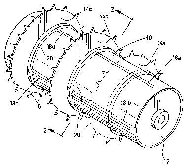
Figure 1 is a perspective illustration of a drive roller in accordance with
the invention, showing two sprockets thereon, and a third sprocket being
shown in phantom;
Figure 2 is a section along the line 2-2 of Figure 1;
Figure 2A is a section along line 2A-2A of Figure 2;
Figure 3 is an exploded perspective illustration of the portion of the
sprocket containing the key, and also showing the key and the set;
Figure 4 is a partially cut away perspective of the internal motor drive
of the preferred form of drive roller;
Figure 5 is an exploded perspective illustration of an alternate
embodiment of the invention using a pair of set screws; and,
-6-

CA 02267737 2004-08-31
Figure 6 is a sectional illustration corresponding to Figure 2A, showing
an alternate embodiment.
DESCRIPTION OF A SPECIFIED EMBODIMENT
As already explained, the invention relates to sprockets for driving
belts, in which the sprockets are mounted on drive rollers, The driver rollers
may driven by internal as illustrated in Figure 4, or may be driven by other
means, depending upon the particular application.
As illustrated in Figure 1, the drive roller will consist of a cylindrical
steel drum 10, having end plates 12, and any suitable shaft means (not
shown) extending from either end, by means of which it may be mounted in
suitable bearings (not shown).
Sprockets, in this case three such sprockets, are indicated generally as
14A, 14B, and 14C. Such sprockets typically are formed with external teeth
16, for engaging suitable link portions of a bolt (not shown) such as is well
known in the art.
As best shown in Figure 1, and also in Figure 2, the drum 10 is formed
with, in this case, four semi-cylindrical grooves 18A, 18B, 18C and 18D
along its length. As shown in Figure 1, the grooves are discontinuous
at each end of the drum, for reasons to be described.
The sprockets 14, are formed in the particular case, typically of
thermoplastic material, and having a predetermined thickness. Collars 20 are
-7-

CA 02267737 2004-08-31
formed integrally with sprockets 14 and having a width greater than the
thickness of said sprockets 14, and extend laterally on either side of
sprocket
14, and define opposite ends..
The collars 20 define cylindrical interior surfaces 22.
~
-7a-

CA 02267737 2004-08-31
The interior surfaces 22 define a radius which is slightly greater than
the radius of the surface of the roller 10, so as to provide a slack clearance
between the collar 20 and the drum 10.
At spaced intervals around the collar 20, there are formed
generally cylindrical recesses 24. The cylindrical recesses 24 which extend
around about 220 to 270 degrees define inwardly open gaps 26 spaced apart
by a distance less than the diameter of the cylindrical recess 24. Recesses 24
extend through the collar from one end to the other of each collar, and are
open at each end of the collar.
Within each of the recesses 24, thee is provided a cylindrical steel
key 28. The key 28 makes a snug fit in the cylindrical recess 24, and a
segment of the key 28 extends out through the gap or slot 26 (Figure 3) into
a respective groove 18.
A threaded inwardly directed opening 30 is formed in the collar 20 of
each sprocket 14, registering and communicating at right angles with the
cylindrical recess 24 for the key 28.
A set screw 32 is threadedly received in the threaded recess 30, and is
received in a corresponding recess 34 in the key 28.
In this way, the keys 28 can be slid endwise, along one of grooves 18
into their respective recesses 24, from one open end of a recess and then can
be securely engaged and held in the recesses, by means of the said screws so
-8-

CA 02267737 2004-08-31
that the keys 28 cannot escape.
As is well known, thee is a tendency on this type of belt drive for the
belt to wander or move sideways and misalign itself slightly. It is desirable
to allow for a minor degree of misalignment. For this reason, the two
sprockets 14A and 14C, can slide to a minor extent, sideways. The
-8a-

= CA 02267737 1999-03-30
keys 28 will ride in their corresponding grooves 18, and allow a sliding
movement while maintaining a good metal-to-metal torque.
The central sprocket 14B however is secured in position so as to
prevent any major misalignment of the belt. This securing of the central
sprocket 14B is achieved by providing a set screw 36 (Figure 2A) which is
longer than the rest of the set screws. In this case, the recess 34 in the key
28 extends all the way through the key. The set screw 36 is then simply
tightened down until it securely engages the semi-cylindrical groove, and in
this way, the sprocket 14B cannot slide to and fro.
A further embodiment is shown in Figures 5 and 6. In this case, the
single set screw 36 of the embodiments of Figures 1 through 4 is replaced
by pairs of set screws. In the Figure 5 embodiment pairs of set screws 32A
and 32B are used, to hold the key 28 in position. The inner set screw 32B is
inserted first into the recess 30, and the second set screw 32A is then
inserted behind the set screw 32B and is tightened up against it so as to
prevent it from becoming loosened.
In the Figure 6 embodiment, a pair of set screws 36A and 36B are
shown. The set screw 36B enters completely through the pin 28, and
engages the roller 10.
The second set screw 36A is then inserted and tightened up behind it
so as to prevent it from becoming dislodged.
-9-

CA 02267737 1999-03-30
The manufacturer of the cylindrical sprocket and semi-cylindrical
grooves is relatively easy to carry out with a great degree of precision. The
use of the blind ends on the grooves 18 prevents the sprockets 14 from
sliding off one end of the roller.
Assembly of the sprockets on the roller is simple to achieve, since
they can simply be slid onto the roller, without their keys 28 in position.
Once on the roller, the keys 28 can simply be inserted into their recesses 24
and the set screws 32 tightened up.
All of these numerous manufacturing and assembly advantages lead to
a greatly improved drive roller for such belts, which is both easier and more
economical to make, and at the same time has a greatly increased working
life, since all torque is carried through metal to metal contact without
friction
as between plastic and metal, as was the case in other such drives.
While reference has been made herein to cylindrical sockets and
cylindrical keys 28, it will of course be appreciated that the sockets may be
of any desired shape, and that the metal keys while preferably being
cylindrical for ease of manufacture, may, in fact, be of any appropriate
shape, preferably an arcuate shape, without departing from the scope of the
invention.
The foregoing is a description of a preferred embodiment of the
invention which is given here by way of example only. The invention is not
to be taken as limited to any of the specific features as described, but
-10-

CA 02267737 1999-03-30
comprehends all such variations thereof as come within the scope of the
appended claims.
-1.1.-

Dessin représentatif
Une figure unique qui représente un dessin illustrant l'invention.
États administratifs

2024-08-01 : Dans le cadre de la transition vers les Brevets de nouvelle génération (BNG), la base de données sur les brevets canadiens (BDBC) contient désormais un Historique d'événement plus détaillé, qui reproduit le Journal des événements de notre nouvelle solution interne.

Veuillez noter que les événements débutant par « Inactive : » se réfèrent à des événements qui ne sont plus utilisés dans notre nouvelle solution interne.

Pour une meilleure compréhension de l'état de la demande ou brevet qui figure sur cette page, la rubrique Mise en garde , et les descriptions de Brevet , Historique d'événement , Taxes périodiques et Historique des paiements devraient être consultées.

Historique d'événement

Description Date
Inactive : Périmé (brevet - nouvelle loi) 2019-03-30
Requête visant le maintien en état reçue 2014-02-25
Requête visant le maintien en état reçue 2013-03-07
Accordé par délivrance 2008-08-12
Inactive : Page couverture publiée 2008-08-11
Inactive : Taxe finale reçue 2008-05-16
Préoctroi 2008-05-16
Un avis d'acceptation est envoyé 2008-02-06
Lettre envoyée 2008-02-06
Un avis d'acceptation est envoyé 2008-02-06
Inactive : Approuvée aux fins d'acceptation (AFA) 2007-11-20
Exigences relatives à la révocation de la nomination d'un agent - jugée conforme 2007-08-28
Inactive : Lettre officielle 2007-08-28
Exigences relatives à la nomination d'un agent - jugée conforme 2007-08-28
Demande visant la nomination d'un agent 2007-08-03
Demande visant la révocation de la nomination d'un agent 2007-08-03
Modification reçue - modification volontaire 2007-08-03
Inactive : Dem. de l'examinateur par.30(2) Règles 2007-02-05
Inactive : Lettre officielle 2006-10-25
Inactive : Paiement correctif - art.78.6 Loi 2006-10-10
Modification reçue - modification volontaire 2004-08-31
Exigences relatives à la nomination d'un agent - jugée conforme 2004-03-22
Inactive : Lettre officielle 2004-03-22
Lettre envoyée 2004-03-22
Exigences relatives à la révocation de la nomination d'un agent - jugée conforme 2004-03-22
Demande visant la révocation de la nomination d'un agent 2004-03-18
Demande visant la nomination d'un agent 2004-03-18
Demande visant la nomination d'un agent 2004-02-26
Exigences pour une requête d'examen - jugée conforme 2004-02-26
Toutes les exigences pour l'examen - jugée conforme 2004-02-26
Demande visant la révocation de la nomination d'un agent 2004-02-26
Requête d'examen reçue 2004-02-26
Inactive : Grandeur de l'entité changée 2003-03-26
Demande publiée (accessible au public) 2000-09-30
Inactive : Page couverture publiée 2000-09-29
Inactive : CIB en 1re position 1999-05-20
Inactive : Demandeur supprimé 1999-05-05
Inactive : Certificat de dépôt - Sans RE (Anglais) 1999-05-05
Demande reçue - nationale ordinaire 1999-05-05

Historique d'abandonnement

Il n'y a pas d'historique d'abandonnement

Taxes périodiques

Le dernier paiement a été reçu le 2008-03-11

Avis : Si le paiement en totalité n'a pas été reçu au plus tard à la date indiquée, une taxe supplémentaire peut être imposée, soit une des taxes suivantes :

  • taxe de rétablissement ;
  • taxe pour paiement en souffrance ; ou
  • taxe additionnelle pour le renversement d'une péremption réputée.

Les taxes sur les brevets sont ajustées au 1er janvier de chaque année. Les montants ci-dessus sont les montants actuels s'ils sont reçus au plus tard le 31 décembre de l'année en cours.
Veuillez vous référer à la page web des taxes sur les brevets de l'OPIC pour voir tous les montants actuels des taxes.

Titulaires au dossier

Les titulaires actuels et antérieures au dossier sont affichés en ordre alphabétique.

Titulaires actuels au dossier
VAN DER GRAAF, INC.
Titulaires antérieures au dossier
ALEXANDER D. KANARIS
Les propriétaires antérieurs qui ne figurent pas dans la liste des « Propriétaires au dossier » apparaîtront dans d'autres documents au dossier.
Documents

Pour visionner les fichiers sélectionnés, entrer le code reCAPTCHA :


Pour visualiser une image, cliquer sur un lien dans la colonne description du document (Temporairement non-disponible). Pour télécharger l'image (les images), cliquer l'une ou plusieurs cases à cocher dans la première colonne et ensuite cliquer sur le bouton "Télécharger sélection en format PDF (archive Zip)" ou le bouton "Télécharger sélection (en un fichier PDF fusionné)".

Liste des documents de brevet publiés et non publiés sur la BDBC .

Si vous avez des difficultés à accéder au contenu, veuillez communiquer avec le Centre de services à la clientèle au 1-866-997-1936, ou envoyer un courriel au Centre de service à la clientèle de l'OPIC.

({010=Tous les documents, 020=Au moment du dépôt, 030=Au moment de la mise à la disponibilité du public, 040=À la délivrance, 050=Examen, 060=Correspondance reçue, 070=Divers, 080=Correspondance envoyée, 090=Paiement})


Description du
Document 
Date
(aaaa-mm-jj) 
Nombre de pages   Taille de l'image (Ko) 
Dessin représentatif 2000-09-25 1 15
Description 1999-03-29 11 319
Abrégé 1999-03-29 1 21
Revendications 1999-03-29 4 91
Revendications 2004-08-30 5 193
Abrégé 2004-08-30 1 14
Description 2004-08-30 13 349
Revendications 2007-08-02 6 205
Dessins 1999-03-29 3 83
Dessin représentatif 2008-07-24 1 18
Courtoisie - Certificat d'enregistrement (document(s) connexe(s)) 1999-05-04 1 116
Certificat de dépôt (anglais) 1999-05-04 1 165
Rappel de taxe de maintien due 2000-12-03 1 112
Rappel - requête d'examen 2003-12-01 1 123
Accusé de réception de la requête d'examen 2004-03-21 1 176
Avis du commissaire - Demande jugée acceptable 2008-02-05 1 164
Taxes 2003-03-16 1 34
Taxes 2002-03-18 1 28
Taxes 2001-03-22 1 28
Correspondance 2004-02-25 2 58
Correspondance 2004-03-21 1 15
Correspondance 2004-03-21 1 18
Taxes 2004-03-17 1 35
Correspondance 2004-03-17 2 69
Taxes 2005-03-13 1 32
Taxes 2006-03-13 1 32
Correspondance 2006-10-24 1 15
Taxes 2007-02-22 1 33
Correspondance 2007-08-02 8 282
Correspondance 2007-08-27 1 15
Correspondance 2007-08-27 1 17
Correspondance 2008-05-15 2 57
Taxes 2008-03-10 1 46
Taxes 2009-03-19 1 49
Taxes 2010-03-02 2 64
Taxes 2011-03-03 2 60
Taxes 2012-03-14 2 64
Taxes 2013-03-06 2 62
Taxes 2014-02-24 2 64
Taxes 2015-03-01 1 25
Taxes 2016-02-28 1 25
Paiement de taxe périodique 2017-03-05 1 25
Paiement de taxe périodique 2018-02-25 1 25