Note : Les descriptions sont présentées dans la langue officielle dans laquelle elles ont été soumises.
ca.~~1RR.1999 ,x:45 EOC PNTE~~TL~EpT. W~NDLF'~~'-IRN N0.2~4 P.?
98B119USA.CA/MW
-1-
SEPARATION OI= AIR
BACKGROUND OF THE INVENTION
This invention relates to a method of and apparatus for the separation of air.
The separation of air by rectification is very well known indeed.
Rectification is a
method in which mass exchange is effected between a descending stream of
liquid
and an ascending stream of vapour such that thE: ascending stream of vapour is
enriched in a more volatile component (nitrogen) of the mixture to be
separated and
the descending stream of liquid is enriched in a less volatile component
(oxygen) of
the mixture to be separated.
It is known to separate air in a double rectification column comprising a
higher
pressure rectification column which receives a stream of purified, compressed,
vaporous air at a temperature suitable for its separation by rectification,
and a lower
pressure rectification column which recEives a stream of oxygen-enriched
liquid air
for separation from the higher pressure rectification column, and which is in
heat
exchange relationship with the higher pressure rectification column through a
condenser-reboiler, ofi which the condenser provides liquid nitrogen reflux
for the
separation and the reboiler provides an upward flow of nitrogen vapour in the
lower
pressure rectification column.
The double rectification column may be operated so as to produce an oxygen
fraction at the bottom of the lower pressure column and a nitrogen fraction at
the top
of the lower pressure column. The oxygen fraction may be essentially pure,
containing less than 0.5% by volume of impurities, or may be impure containing
up
to 50°~o by volume of impurities.
There is a net requirement for refrigeration to be provided to the air
separation plant.
At least part of this requirement arises from the operation of the double
rectification '
column at cryogenic temperatures. Particularly if none of the products of the
air
CA 02267805 1999-03-31
.~0 . h1RR . 1999 ~c : 45 F~nC P.RTE!~T ~~ ::~EPT . i-!i NDLE~~HR~~1 N0. 234 P
. 4
98B119USA.CA/MW
-2-
separation is taken in liquid state, the requirements for refrigeration are
typically met
by raising the pressure of a part of the air to at (east 2 bar above the
operating
pressure at the top of the higher pressure column and expanding it with the
performance of external work in an expansion turbine which exhausts into the
lower
pressure column. Typically, the turbine is coupled to a booster-compressor
which°
raises the pressure of the air to above that at the. top of the higher
pressure column.
An air separation plant typically consumes a considerable amount of power. Its
is
therefore desirable for the air separation plant to have a configuration which
enables
power consumption to be minimised without unduly increasing its capital cost.
In
order to minimise the power consumption much attention in the art has recently
been focused upon operating the lower pressure rectification column with two
reboilers, one operating at a higher temperature and being heated by a flow of
the
air to be separated, and the other operating at a lower temperature and being
heated by a flow of nitrogen separated in the higher pressure rectification
column. A
disadvantage of such plant is that the requirement for a second reboiler adds
to its
capital cost.
US-A-5 337 570 provides examples of a yet further kind of air separation
plant. ,
.~ There is a first condenser-reboiler which, condenses a part of the top
nitrogen
fraction separated in the higher pressure column. The condensation is effected
by
indirect heat exchange with a stream of a bottom oxyg~n-enriched liquid
fraction
formed in the higher pressure column. As a result) the stream of the bottom
oxygen-
enriched liquid fraction is partially reboiled. Resulting vapour and residual
liquid are
fed to the lower pressure rectification column. The plant employs a single
generator-
loaded expansion turbine exhausting into the lower pressure column. The air to
be
separated is compressed in a main, plural stage, compressor. The main air feed
to
the higher pressure rectification column is taken from a lower pressure stage
than
the feed to the expansion turbine.
CA 02267805 1999-03-31
9~. MRR. 1999 9: 45 EOC PRTE~IT~~ DEFT. t.JIfJD~.E~>HRt~1 N0.234 P. 5
98B 119USA.CA/MW
_g_
It is an aim of the present invention to provide a method and apparatus for
separating air by rectification which are able to be operated at a favourable
net
power consumptioh without imposing on the apparatus an unacceptably high
capital
cast and without the need to have two reboilers ;associated with the lower
pressure
rectification column.
SUMMARY OP THE INVENTION
According to the present invention there is provided a method of separating
air by
rectification, including compressing the air to a first pressure; without
further
compression cooling in a main heat exchanger a first flow of the compressed
air to a
temperature suitable for its separation by rectification and introducing the
first flow
into the higher pressure column of a double rectification column comprising,
in
addition to the higher pressure column, a lower pressure column, in which a
bottom
oxygen fraction having an oxygen content in the range of 50 to 96 mole per
cent is
formed; expandirig with the performance of external work a second flow of the
compressed air; introducing the expanded second flow into the lower pressure
column, and taking an impure oxygen product from the said bottom fraction,
wherein
.~. the external work is the generation of electrical power, characterised in
that the
double rectification column additionally includes a condenser--reboiler
placing the
higher pressure column in heat exchange relationship with the lower pressure
column, and the expansion of the second flow of the compressed air takes place
without further compression of the second flow upstream thereof.
The present invention also provides apparatus for separating air by
rectification,
including a double rectification column comprising a higher pressure column
and a
lower pressure column, at least one air compressor for compressing the air to
a first
pressure, a main heat exchanger for cooling the first flow of the compressed
air to a.
temperature suitable for its separation by rectificailion, an inlet to the
higher pressure
column for the first flow, an expansion turbine for expanding with the
pertormance of
CA 02267805 1999-03-31
3~. NRR. 1999 9:46 B0C PRTEf~IT~ DEFT. IJIt~DLE;=HGM N0. 234 P. 6
96B119USA.CA/MW
-4-
external work a second flow of the compressed .air having an inl~t for the
second
flow of the compressed air and an outlet communicating with the lower pressure
column, the expansion turbine being loaded by an electrical generator, and an
outlet
from the lower pressure column for an irnpure oxygen product formed of a
bottom
fraction having an oxygen content in the range of 50 tv 96 mole per cent)
characterised in that there is no additional compression means for raising the
pressure of either the said first flow or the said second flow of the
compressed air
above the first pressure, and the double rectification column additionally
includes a
condenser-reboiler able to place the higher pressure column in heat exchange
relationship with the lower pressure column.
The method and apparatus according to the invs~ntion offer a number of
advantages.
First, they enable a particularly large proportion of the air to be expanded
with the
performance of external work and introduced into the lower pressure column.
This
makes it possible to operate the lower pressure <:olumn relatively efficiently
and with
a relatively low vapour traffic beiaw the level at which the expanded air is
introduced.
In addition, the Load on the condenser-reboiler is reduced. The effective
diameter of
the lower pressure column may be reduced in the lower part of the lower
pressure
column, thereby making possible a reduction in tl'ne total area of liquid-
vapour
contact surfaces. The size of the condenser-reboiler may also be reduced.
Although operation of the method and apparatus according to the invention in
such a
manner has the effect of widening the temperature difiference in the main heat
exchanger between flow being cooled and flow being warmed, this disadvantage
is
more than compensated far by the relatively high efficiency with which the
lower
pressure column can be operated, particularly because a wider temperature
difference in the main heat exchanger permits either the pressure drop in) or
the '
heat transfer area per unit volume of the main heat exchanger to be reduced,
or
permits both these advantages to be obtained. Third, the conventional booster-
compressor associated with the expansion turbine is eliminated. Fourth, the
method
and apparatus according to the invention are ablE> to be used to export a
significant
amount of electrical power, thereby reducing the net power consumption.
CA 02267805 1999-03-31
~~~ . MAR . 1 '~99 8 : 46 BGC pATEraT ~, DEF=T . L II NDl_E:;HAM N0. 284 F . r
98B119USA.CA/MW
-5-
Typically, the oxygen product is withdrawn from the lower pressure
rectification
column in liquid state, is pressurised) and is vaporised in indirect heat
exchange with
a third flow of the compressed air which is at a second pressure higher than
the first
pressure. This heat exchange may be performed in the main heat exchanger or in
a
separate one. Such examples of the method and apparatus according to the
invention a~'e particularly suited to producing an oxygen product having an
oxygen
content in the range of 70 to 90 mole per cent of oxygen, preferably in the
range of
75 to 85 mole per cent. In the preferred example?s, preferably at least 22% by
volume of the flow of air to be separated forms the expanded second flow, more
preferably from 23% to 30% by volume thereof. In such examples, the first flow
of
compressed air typically constitutes less than ~-5% by volume of the total
flow of the
air to be separated.
Alternatively, the oxygen product may be withdrawn from the lower pressure
rectification column in vapour state) and, if desired, compressed to a desired
delivery y
pressure downstream of being warmed to a non-cryogenic temperature in the main
heat exchanger. In this case, there is no need to condense a third flow of the
compressed air. As a result, it becomes possiblE: to form the second flow of
compressed air as an even greater proportion of the total flow of air to be
.,~ compressed. For example, if the oxygen produce contains from 70 to 90 mole
per
cent of oxygen, typically at (east 40% of the total flow of air to be
separated may
form the second flow of compressed air.
Preferably, the expansion turbine has a ratio of inlet pressure to outlet
pressure in
the range of 2.5:1 to 3.5:1.
The method according to the present invention is particularly suited to the
separation
of air when no liquid products of the separation are taken or when the total
production of liquid products is less than 10%, preferably less than 5%, more
preferably less than 2%, of the total production of the oxygen product.
CA 02267805 1999-03-31
3c~ . r 1AR . 1996 9 : 4E E0C PATEr~T~ DEP T . L JI w~Lr!_E:;HAfo N0. 2E4 P .
98B119USA.CA/MW
Preferably, the first flow of compressed air i.s divided from the second flaw
thereof
typically in the main heat exchanger rather than upstream thereof. In any
event, the
first and second flows are preferably denied frorn the said air compressor at
the
same pressure
Preferably, the compressed air is purified upstream of the main heat
exchanger.
The higher pressure column and the lower pressure column may both be
constituted
by one or more vessels in which liquid and vapour phases are countercurrsntly
contacted to effect separation of the air) as, for example, by contacting the
vapour
and liquid phases on packing elements or on a series of vertically spaced
trays or
plates mounted within the vessel or vessels.
BRIEF DESCRIPTION OF THE DRAWINCyS
The method and apparatus according to the invention will now be described by
way
of example with reference to the accompanying drawings, in which;
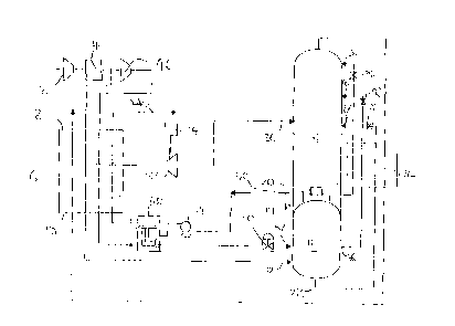
Figure 1 is a schematic flow diagram of a first air separation apparatus
according to
the invention, and
FigurE 2 is a schematic flow diagram of a second air separation apparatus
according
to the invention.
Like parts in the drawings are indicated by the same reference numerals,
DETAILED DESCRIPTION OF THE INVENTION
Referring to Figure 1 of the drawings, a stream of air is compressed in a main
air
compressor 2. Heat of compression is extracted from the resulting compressed
air
ir1 an after-cooler (not shown) associated with the main air compressor 2.
CA 02267805 1999-03-31
6~. MAR. 1999 6: 46 EOC PATE~JT~ DEPT. I:ITNDLE:;HAM N0. cc~34 P. 9
98i3119USA.CA/MW
The compressed air stream is purified in an adsorption unit 4. The
purification
comprises removal from the air flow of relatively high boiling point
impurities,
particularly water vapour and carbon dioxide, which would otherwise freeze in
low
temperature parts of the apparatus. The unit 4 may effect the purification by
pressure swing adsorption or temperature swingy adsorption. The unit ~ may
additionally include one or more layers of catalyst for the removal of carbon
monoxide and hydrogen impurities. Such removal of carbon monoxide and
hydrogen impurities is described in EP-A-438 282. The construction and
operation
of adsorptive purification units are well known and need not be described
further
herein.
Downstream of the purification unit 4, the comer~ssed air stream passes into a
main
heat exchanger 6 through its warm end 8. At an intermediate region of the main
heat exchanger 6 the compressed air stream is divided into first and second
flows.
The first flow continues through the main heat exchanger 6 and leaves through
the
cold end 10 thereof at or close to its dew point and therefore at a
temperature
suitable for its separation by rectification. The first flow of compressed air
passes
from the cold end 10 of the main exchanger 8 through an inlet 12 into a lower
region
of a higher pressure column 16 forming a double rectification column 14 with a
lower
pressure column 18 and a (single) condenser-reboiler 20. (There is no other
condenser-reboiler present placing the higher prcasure column 16 in indirect
heat
exchange relationship with the lower pressure column 18,) '
In operation, the air is separated in the higher pressure column 16 into a
bottom
oxygen-enriched liquid fraction and a top nitrogen vapour fraction. A stream
of the
oxygen-enriched liquid fraction is withdrawn from the bottom of the higher
pressure
column 16 through an outlet 22. The oxygen-enriched liquid air stream is sub-
cooled in a further heat exchanger 24, is passed through a Joule-Thomson or
throttling valve 26, and is introduced into a chosen intermediate region of
the lower
pressure column 18 through an inlet 27.
CA 02267805 1999-03-31
.''wl, hlaR. 1999 c : 47 BGC PHTEYJ T ~ DEt='T, 1J1:'vD~E'.=HAM N0. 2,'-'-~4
P. 18
98B119USA.CA/MW
-8-
Nitrogen vapour flows from the top of the higher pressure column 16 into the
condenser-reboiler 20 and is condensed thørein by indirect heat exchange with
a
boiling impure liquid oxygen fraction at the bottom of the lower pressure
column 18.
A part of the resulting liquid nitrogen condensatEa is returned to the column
16 as
reflux. The remainder of the condensate is sub-cooled by passage through the
heat
exchanger 24, is passed through a throttling or J~ouie-Thomson valve 28 and is
introduced into the top of the lower pressure column 18 as reflux through an
inlet 30.
The oxygen-enriched liquid air withdrawn from the higher pressure column 16
through the outlet 22 forms one source of the air that is separated in the
lower
pressure column 18. Another source of this air i.s the second flow of
compressed air
which is divided from the first flow of compressed air at an intermediate
region of the
main heat exchanger 6. The second flow of compressed air is withdrawn from the
intermediate region of the main heat exchanger ~3 and is expanded in an
expansion
turbine (sometimes referred to as a turbo-expander) 32 with the performance of
external work. This external work is the operation of an electrical generator
34 to
which the turbine 32 is coupled. The resulting expanded air leaves the turbine
32 at
approximately the pressure of the lower pressurE~ column 18 and is introduced
into
an intermediate region thereof through an inlet 38. The fbows of air are
separated in
the lower pressure column 18 into a top nitrogen vapour fraction and a bottom
..~ impure liquid oxygen fraction typically containing from 70 to 90 mole per
cent of
oxygen. The condenser-reboiler is effective to re~boil the bottom impure
liquid
oxygen fraction by indirect heat exchange with the condensing nitrogen. A part
of
the resulting oxygen vapour ascends the column 18 and is contacted therein
with
downflowing liquid. The remainder of the impure oxygen vapour is withdrawn
from
the lower pressure column 18 through an outlet 40, is warmed to a non-
cryogenic
temperature, i.e, one a little below ambient, by passage through the main heat
exchanger 6 from its cold end 10 to its warm end 8. The resulting warmed
oxygen
product is compressed to a desired delivery press>ure in an oxygen compressor
42.
The compressed oxygen product passes to an oxygen delivery pipeline 44. A
nitrogen product (or waste) stream is taken from the top of the lower pressure
column 18, is used to cool the heat exchanger 24, and, doirvnstream of its
passage
CA 02267805 1999-03-31
2~. MRR. 1999 ~: 47 BOC PATENTS DEFT. I.ITNL~LE:'HRt~1 N0.2~4 P. 11
98B119USA.CA/MW
_g_
therethrough, is passed through the main heat Exchanger 6 from its cold end 10
to
its warm end 8,
Referring now to Figure 2 of the drawings, the plant shown therein is
generally
similar to that illustrated in Figure 1 save that thc~ oxygen product is
withdrawn from
the lower pressure column 18 through the outlet 40 in liquid state and is
pressurised
in a liquid pump 54 to a desired delivery pressure. A part of the purified air
is taken
from the purification unit 4 and is further comprE~ssed in a booster
compressor 46.
The resulting further compressed flow of air passes through the main heat
exchanger 6 from is warm end 8 to its cold end 10 and is thereby cooled to its
liquefaction point. The resulting cooled flow of farther compressed air is
condensed
in a condenser-vaporiser 4F3 by indirect heat exchange with the pressurised
flow of
impure liquid oxygen product. As a result) the flow of impure liquid oxygen
product is
vaporised. The condensation of the air flowing through the condenser-vaporiser
48
is typically complete. The resulting condensate ;passed through a throttling
or Joule-
Thomson valve 50 and is introduced into the higher pressure column 16 through
an
inlet 52 at a level above that of the inlet 12. The oxygen vapour formed in
the
condenser-vaporiser 48 flows through the main heat exchanger 6 from its cold
end
to its warm end 8 and thus passes to the product oxygen delivery line 44 at a
desired pressure. Typically, a flow of liquid having approximately the same.
composition as that of air is withdrawn from an intermediate outlet 56 of the
higher
pressure column 16, is sub-cooled by passage through the heat exchanger 24, is
passed through a throttling or Joule-Thomson valve 58 and is introduced
through an
inlet 60 into the lower pressure column 18. Alternatively, the flow of
condensed
liquid air may be divided upstream of the valve 50 and a part of the flow
introduced
into the lower pressure column 18 through a throttling or Joule-Thomson valve
(not
shown).
In a typical example of the operation of the apparatus shown in Figure 2, the
oxygen
product withdrawn from the lower pressure column 18 through the outlet 40 may
contain 80 mole per cent of oxygen and may be raised to a pressure of about
4.3
CA 02267805 1999-03-31
.=N , P1RR . 2 99'~ S : 42 BOC PRTEI~IT:_ DEP T . LJ I Ni~LE;>HRr~t NO . 234 P
. 12
988119USA.CA/MW
- 1p-
bar in the pump 54~. The turbine 32 has an inlet pressure of about 3.8 bar and
an
outlet pressure of about 1.25 bar'. AbQUt 4p°/4 bye volume of the total
flow of air is
introduced into the higher pressure column 16 through the inlet 12, about 25%
by
volume into the lower pressure column 18 through the inlet 16, and the
remainder
into the higher pressure column 16 through the inlet 52.
In the apparatuses shown in Figure 1 and 2 the main air compressor 2 sets the
inlet
pressure of the turbine 32 and the pressure of the inlet 12 of the higher
pressure
column 16. The air pressure at the inlet to the turbine 32 will be some parts
of a bar
less than the outlet pressure of the compressor 2 as a result of pressure drop
through the purification unit 4 and the main heat exchanger 6. Similarly, the
pressure at the inlet 12 to the higher pressure column 16 will be a few parts
of a bar
less than the outlet pressure of the main air compressor 2 as a result of
pressure
drop through the main heat exchang~r 6 in the purification unit 4. Further,
the
expansion turbine 32 is the sole expansion turbine employed in both the
apparatus
shown in Figure 1 and that shown in Figure 2 of t!he drawings,
CA 02267805 1999-03-31