Sélection de la langue

Search

Sommaire du brevet 2267846 

Énoncé de désistement de responsabilité concernant l'information provenant de tiers

Une partie des informations de ce site Web a été fournie par des sources externes. Le gouvernement du Canada n'assume aucune responsabilité concernant la précision, l'actualité ou la fiabilité des informations fournies par les sources externes. Les utilisateurs qui désirent employer cette information devraient consulter directement la source des informations. Le contenu fourni par les sources externes n'est pas assujetti aux exigences sur les langues officielles, la protection des renseignements personnels et l'accessibilité.

Disponibilité de l'Abrégé et des Revendications

L'apparition de différences dans le texte et l'image des Revendications et de l'Abrégé dépend du moment auquel le document est publié. Les textes des Revendications et de l'Abrégé sont affichés :

  • lorsque la demande peut être examinée par le public;
  • lorsque le brevet est émis (délivrance).
(12) Brevet: (11) CA 2267846
(54) Titre français: MACHINE MUNIE D'UN EXCAVATEUR DE CASES A TRAVERSES
(54) Titre anglais: A MACHINE HAVING A SLEEPER CRIB EXCAVATOR
Statut: Périmé et au-delà du délai pour l’annulation
Données bibliographiques
(51) Classification internationale des brevets (CIB):
  • E01B 27/04 (2006.01)
  • E01B 27/11 (2006.01)
(72) Inventeurs :
  • THEURER, JOSEF (Autriche)
(73) Titulaires :
  • FRANZ PLASSER BAHNBAUMASCHINEN-INDUSTRIEGESELLSCHAFT M.B.H.
(71) Demandeurs :
  • FRANZ PLASSER BAHNBAUMASCHINEN-INDUSTRIEGESELLSCHAFT M.B.H. (Autriche)
(74) Agent: RICHES, MCKENZIE & HERBERT LLP
(74) Co-agent:
(45) Délivré: 2006-10-03
(22) Date de dépôt: 1999-03-31
(41) Mise à la disponibilité du public: 1999-10-01
Requête d'examen: 2002-04-10
Licence disponible: S.O.
Cédé au domaine public: S.O.
(25) Langue des documents déposés: Anglais

Traité de coopération en matière de brevets (PCT): Non

(30) Données de priorité de la demande:
Numéro de la demande Pays / territoire Date
A 571/98 (Autriche) 1998-04-01

Abrégés

Abrégé français

Une machine (1) est constituée d'un châssis de machine (5), supporté sur des bogies pour rails, sur lequel une excavatrice de berceau traverse (11) est agencée. Celle-ci sert à retirer un ballast se trouvant dans un berceau traverse (2) d'une voie ferrée (3). L'excavatrice de berceau traverse (11) est réalisée sous la forme d'une chaîne de déblayage sans fin (12) destinée à être mise en rotation au moyen d'un entraînement. Afin d'abaisser un segment de reprise de ballast (15) localisé dans la zone d'extrémité la plus basse dans le berceau traverse (2) situé entre les rails (16) de la voie (3), la chaîne de déblayage (12) est montée en vue d'un réglage vertical sur le châssis de machine (5) et reliée à un entraînement de déplacement.


Abrégé anglais

A machine (1) consists of a machine frame (5), supported on on-track undercarriages, on which a sleeper crib excavator (11) is arranged. The latter serves for removing ballast situated in a sleeper crib (2) of a track (3). The sleeper crib excavator (11) is formed as an endless clearing chain (12) designed to be set in rotation by means of a drive. In order to lower a ballast take-up segment (15) located in the lowermost end region into the sleeper crib (2) situated between rails (16) of the track (3), the clearing chain (12) is mounted for vertical adjustment on the machine frame (5) and connected to a displacement drive.

Revendications

Note : Les revendications sont présentées dans la langue officielle dans laquelle elles ont été soumises.


6
Claims
1. A machine (1) having a machine frame (5) supported on on-track
undercarriages (4) as well as a sleeper crib excavator (11) for removing
ballast
situated in a sleeper crib (2) of a track (3), characterized in that the
sleeper
crib excavator (11) is formed as an endless clearing chain (12), designed to
be
set in rotation by means of a drive (14), which, in order to lower a ballast
take-
up segment (15) located in the lowermost end region into the sleeper crib (2)
situated between rails (16) of the track (3), is mounted for vertical
adjustment
on the machine frame (5) and connected to a displacement drive (18).
2. A machine according to claim 1, characterized in that the clearing chain
(12) is designed for rotation and vertical adjustment in a plane of rotation
(21)
extending perpendicularly to the longitudinal direction of the machine and at
an
angle (a) to a base plane (20) formed by wheel contact points (19) of the on-
track undercarriages (4).
3. A machine according to claim 1 or 2, characterized in that the clearing
chain (12) is connected to flanged rollers (22) for placement upon the rails
(16)
of the track (3).
4. A machine according to claim 3, characterized in that the flanged rollers
(22) are designed for adjustment in the plane of rotation (21) as well as in
the
direction of displacement of the clearing chain (12).
5. A machine according to any one of claims 1 to 4, characterized in that the
sleeper crib excavator (11) is composed of the clearing chain (12), intended
to
be lowered between the rails (16) of the track (3), and a clearing shield (13)
positioned in a vertical plane (32) extending in the longitudinal direction of
the machine and intended to be lowered in the sleeper end region (33) located
between the rail (16) and a bedding shoulder (43) of a ballast bed (42), the
clearing shield (13) being connected to drives (37,38) for independent
vertical
and transverse displacement.

Description

Note : Les descriptions sont présentées dans la langue officielle dans laquelle elles ont été soumises.

CA 02267846 1999-03-31
NA 528
1
A MACHINE HAVING A SLEEPER CRIB EXCAVATOR
The invention relates to a machine having a machine frame supported
on on-track undercarriages as well as a sleeper crib excavator for removing
ballast situated in a sleeper crib of a track.
A machine of this kind for exchanging damaged sleepers is already
known from US 5 125 345, wherein ballast situated in a sleeper crib adjoining
a
sleeper to be exchanged is removed with the aid of a sleeper crib excavator.
The sleeper crib excavator is composed of four plate-shaped clearing elements
which extend in the longitudinal direction of the machine and are arranged at
a distance from one another in the transverse direction of the machine. Said
clearing elements are transversely displaceable in the direction towards the
ballast bed shoulders in respective pairs independently of one another by
means of separate drives. Owing to said transverse movement, the ballast
present in the sleeper crib can be shifted towards the respective ballast bed
shoulder.
According to FR 2 588 023 A1 and DE 1 1 16 257, machines are known
which have a clearing member, designed as an endless chain, for taking
up ballast. Said clearing member, designed in the way of a bucket chain, is
lowered between the rails of the track in order to thereby transport the
entire
bedding ballast upwards onto a conveyor belt. Removal of the sleepers is
required before lowering the clearing member. In the context of sleeper
renewal, it is additionally known according to US 4,611,541 to arrange an
endless clearing chain between two sleeper changing devices spaced from
one another in the longitudinal direction of the machine, in order to thereby
feed the entire ballast of the ballast bed to a screening plant for cleaning.
Finally, a further machine for cleaning 'the ballast bed is known from
US 5 513 452. A first clearing member located in the front end region of the
machine in the operating direction serves for taking up new ballast deposited
on the track. Said ballast is transported to behind a second clearing device
via a conveyor belt arrangement and is discharged there upon the exposed
formation in order to supplement the ballast cleaned by means of a screening
plant.

CA 02267846 2004-12-23
2
It is the object of the present invention to provide a machine as
specified, by means of which it is possible to accomplish an improved sleeper
crib excavation for facilitating a sleeper renewal.
This object ist achieved with a machine of the specified kind in that the
sleeper crib excavator is formed as an endless clearing chain, designed to be
set in rotation by means of a drive, which, in order to lower a ballast take-
up
segment located in the lowermost end region into the sleeper crib situated
between rails of the track, is mounted for vertical adjustment on the machine
frame and connected to a displacement drive.
By using a clearing chain of this kind, it is possible to remove
substantially the entire ballast situated in the sleeper crib between the
rails.
Additionally, it is also of particular advantage that the ballast engaged by
the
sleeper crib excavator can be removed completely from the track with the aid
of the endless chain and can be stored intermediately. Thus, the following
insertion of a new sleeper can be accomplished unhindered and quickly.
making avoidable in particular a ballast jam which would render difficult the
insertion of the sleeper under the second rail in the direction of insertion.
Further advantages become apparent from the drawing.
The invention will be described in more detail below with reference to an
embodiment represented in the drawing, in which
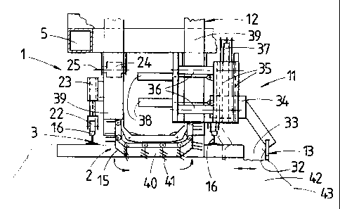
Fig. 1 shows a side view of a machine according to the invention
with a sleeper crib excavator having a clearing chain, and
Fig. 2 shows an enlarged partial view of the sleeper crib excavator
according to arrow II in Fig. 1.
A machine 1, shown in Fig. 1, for clearing a sleeper crib 2 of a track 3
is essentially composed of a machine frame 5 supported on on-track
undercarriages 4. Arranged at a front end - with respect to an operating
direction (arrow 6) - of the machine frame 5 is a driver's and operator's cab
7

CA 02267846 1999-03-31
3
with a central control device 8. An energy unit 10 is provided for supplying
energy to a motive drive 9 as well as to all drives yet to be described.
Arranged
between the two on-track undercarriages 4 is a sleeper crib excavator 1 1
consisting of a clearing chain 12 and a clearing shield 13. The clearing chain
12 is designed endless and able to be set in rotation by means of a drive 14.
The lowermost end region of the clearing chain 12, facing the track 3, is
designed as a ballast take-up segment 15 for being lowered into the sleeper
crib 2 situated between rails 16 of the track 3. To that end, the clearing
chain
12 is mounted on a telescopically elongatable supporting arm 17 which is
fastened to the machine frame 5 and has a displacement drive 18. The clearing
chain 12 is designed for rotation and vertical adjustment in a plane of
rotation
21 extending perpendicularly to the longitudinal direction of the machine and
at
an angle a to a base plane 20 formed by wheel contact points 19 of the on-
track undercarriages 4. The angle a is preferably about 40-50°.
Arranged on
the clearing chain 12 are flanged rollers 22, :>paced from one another in the
transverse direction of the track and respectively associated with a rail 16.
which support the clearing chain 12 on the track 3. The flanged rollers 22 are
respectively connected to a vertical adjustment drive 23. For better support
and
guidance of the clearing chain 12, two rollers 24 are arranged on the machine
frame 5, spaced from one another in the transverse direction of the machine.
Said rollers 24 are mounted for rotation about a horizontal axis 25 extending
in
the transverse direction of the machine. Located at the end of the clearing
chain 12 opposite the ballast take-up segment 15 is a discharge point 26 for
the taken-up ballast. Said discharge point 26 is arranged immediately above a
charging opening 27 of a ballast store 28 located on the machine frame 5. The
floor of said ballast store 28 is in the shape of a conveyor belt 29,
extending in
the longitudinal direction of the machine. which has a discharge end 30
situated
above discharge chutes 31 arranged on the machine frame 5.
Shown in more detail in Fig. 2 is the sleeper crib excavator 1 1 with
the clearing shield 13 for clearing the ballast, arranged in a vertical plane
32
extending in the longitudinal direction of the machine, which is positioned in
a
sleeper end region 33. The clearing shield 13 is attached to a tool carrier 34
which, for its part, is connected to vertical and transverse guides 35.36.
With the aid of vertical and transverse adjustment drives 37,38, the clearing
shield 13 is adjustable along the guides 35,36 both vertically and in the

CA 02267846 1999-03-31
4
transverse direction of the track. The structure of the endless clearing chain
12
- sufficiently known from track bed cleaning machines - can be better observed
in the area of the ballast take-up segment 15. The clearing chain 12,
circulating
outside the ballast take-up segment 15 in trough-shaped guides 39, consists of
a multitude of articulatedly connected chain links 40 which are provided with
so-called scraper fingers 41. These serve to rip the ballast out of the
sleeper
crib 2 and to convey the ballast onward in the guide 39.
The mode of operation of the machined 1 will be described below. To
begin with, said machine is driven to the work site, i.e. up to the sleeper
crib 2 to be cleared. (The old sleeper, not shown, has already been removed
beforehand independently of the machine 1 ). In order to clear away the
ballast
in the sleeper end region 33, first the clearing shield 13 is lowered by
actuation
of the vertical adjustment drive 37. Said clearing shield 13 plunges into a
ballast bed 42 of the track 3 immediately ne>;t to the rail 16 (see position
of clearing shield shown in dash-dotted lines in Fig. 2). Actuation of the
transverse adjustment drive 38 causes the cuearing shield 13 to push the
ballast in the sleeper end region 33 beyond a bedding shoulder 43 of the
ballast bed 42. For the purpose of clearing the sleeper crib 2 situated
between the rails 16, the clearing chain 12 is displaced from a transit
position
(represented dash-dotted in Fig. 1 ) into an operating position (full lines in
Fig. 1 ) by actuation of the displacement drive 18. During this, the drive 14
is
already activated, so that the ballast take-up segment 15, with the clearing
chain 12 running (circulating direction according to the small arrows in Fig.
2),
is able to dive without problems into the sleeper crib 2 filled with ballast.
With
the aid of the vertical adjustment drives 23, the clearing chain 12 can be set
to the required immersion depth and supported on the track 3 via the flanged
rollers 22. The ballast ripped from the sleeper crib 2 by means of the scraper
fingers 41 is transported by the clearing chain 12 through the guide 39 and
ejected from the discharge point 26 into the ballast store 28. By actuation of
the conveyor belt 29, the ballast can be reintroduced into the track 3 at any
desired place via the discharge chutes 31. In order to clear the sleeper crib
2
exactly, the machine 1 is moved slightly - i.e. to just in front of a next
sleeper
44 adjoining the cleared sleeper crib 2 - in the operating direction (arrow
6).
With the clearing chain 12 lifted into the transfer position, the machine 1
can
be driven to the next sleeper crib to be cleared. The sleeper crib excavator 1
1

CA 02267846 1999-03-31
is controlled by means of the control device 8 arranged in the drivers and
operator's cab 7. The subsequent installing of a new sleeper into the cleared
sleeper crib 2 is carried out independently of the machine 1 at a later point
in
time, the insertion being expediently effected from the side of the cleared
sleeper end region.
As an alternative to the embodiment described here, it would also be
conceivable to arrange on the machine 1 devices for removal and installation
or
for transport and storage of old and new sleepers.
In order to increase the flexibility of the sleeper crib excavator, it would
also be possible to arrange an additional cle<~ring shield - opposite the
first
clearing shield in the transverse direction of l:he machine - on the machine
frame.

Dessin représentatif
Une figure unique qui représente un dessin illustrant l'invention.
États administratifs

2024-08-01 : Dans le cadre de la transition vers les Brevets de nouvelle génération (BNG), la base de données sur les brevets canadiens (BDBC) contient désormais un Historique d'événement plus détaillé, qui reproduit le Journal des événements de notre nouvelle solution interne.

Veuillez noter que les événements débutant par « Inactive : » se réfèrent à des événements qui ne sont plus utilisés dans notre nouvelle solution interne.

Pour une meilleure compréhension de l'état de la demande ou brevet qui figure sur cette page, la rubrique Mise en garde , et les descriptions de Brevet , Historique d'événement , Taxes périodiques et Historique des paiements devraient être consultées.

Historique d'événement

Description Date
Le délai pour l'annulation est expiré 2018-04-03
Lettre envoyée 2017-03-31
Accordé par délivrance 2006-10-03
Inactive : Page couverture publiée 2006-10-02
Inactive : Taxe finale reçue 2006-07-14
Préoctroi 2006-07-14
Un avis d'acceptation est envoyé 2006-06-15
Lettre envoyée 2006-06-15
Un avis d'acceptation est envoyé 2006-06-15
Inactive : Approuvée aux fins d'acceptation (AFA) 2006-05-29
Modification reçue - modification volontaire 2005-11-08
Inactive : Dem. de l'examinateur par.30(2) Règles 2005-09-06
Modification reçue - modification volontaire 2004-12-23
Inactive : Dem. de l'examinateur par.30(2) Règles 2004-08-03
Inactive : Dem. de l'examinateur art.29 Règles 2004-08-03
Inactive : CIB en 1re position 2004-08-02
Lettre envoyée 2002-05-13
Requête d'examen reçue 2002-04-10
Exigences pour une requête d'examen - jugée conforme 2002-04-10
Toutes les exigences pour l'examen - jugée conforme 2002-04-10
Demande publiée (accessible au public) 1999-10-01
Inactive : Page couverture publiée 1999-09-30
Inactive : CIB en 1re position 1999-05-25
Inactive : Certificat de dépôt - Sans RE (Anglais) 1999-05-06
Exigences de dépôt - jugé conforme 1999-05-06
Demande reçue - nationale ordinaire 1999-05-06

Historique d'abandonnement

Il n'y a pas d'historique d'abandonnement

Taxes périodiques

Le dernier paiement a été reçu le 2006-02-16

Avis : Si le paiement en totalité n'a pas été reçu au plus tard à la date indiquée, une taxe supplémentaire peut être imposée, soit une des taxes suivantes :

  • taxe de rétablissement ;
  • taxe pour paiement en souffrance ; ou
  • taxe additionnelle pour le renversement d'une péremption réputée.

Veuillez vous référer à la page web des taxes sur les brevets de l'OPIC pour voir tous les montants actuels des taxes.

Titulaires au dossier

Les titulaires actuels et antérieures au dossier sont affichés en ordre alphabétique.

Titulaires actuels au dossier
FRANZ PLASSER BAHNBAUMASCHINEN-INDUSTRIEGESELLSCHAFT M.B.H.
Titulaires antérieures au dossier
JOSEF THEURER
Les propriétaires antérieurs qui ne figurent pas dans la liste des « Propriétaires au dossier » apparaîtront dans d'autres documents au dossier.
Documents

Pour visionner les fichiers sélectionnés, entrer le code reCAPTCHA :


Pour visualiser une image, cliquer sur un lien dans la colonne description du document. Pour télécharger l'image (les images), cliquer l'une ou plusieurs cases à cocher dans la première colonne et ensuite cliquer sur le bouton "Télécharger sélection en format PDF (archive Zip)" ou le bouton "Télécharger sélection (en un fichier PDF fusionné)".

Liste des documents de brevet publiés et non publiés sur la BDBC .

Si vous avez des difficultés à accéder au contenu, veuillez communiquer avec le Centre de services à la clientèle au 1-866-997-1936, ou envoyer un courriel au Centre de service à la clientèle de l'OPIC.


Description du
Document 
Date
(aaaa-mm-jj) 
Nombre de pages   Taille de l'image (Ko) 
Dessin représentatif 1999-09-21 1 11
Abrégé 1999-03-31 1 19
Description 1999-03-31 5 241
Dessins 1999-03-31 1 30
Revendications 1999-03-31 1 46
Page couverture 1999-09-21 1 37
Abrégé 2004-12-23 1 16
Description 2004-12-23 5 240
Revendications 2004-12-23 1 44
Dessin représentatif 2006-09-05 1 13
Page couverture 2006-09-05 1 42
Courtoisie - Certificat d'enregistrement (document(s) connexe(s)) 1999-05-06 1 116
Certificat de dépôt (anglais) 1999-05-06 1 165
Rappel de taxe de maintien due 2000-12-04 1 112
Accusé de réception de la requête d'examen 2002-05-13 1 179
Avis du commissaire - Demande jugée acceptable 2006-06-15 1 162
Avis concernant la taxe de maintien 2017-05-12 1 178
Taxes 2003-02-03 1 35
Taxes 2002-03-15 1 38
Taxes 2001-03-12 1 36
Taxes 2004-02-20 1 37
Taxes 2005-02-17 1 34
Taxes 2006-02-16 1 36
Correspondance 2006-07-14 1 45