Note : Les descriptions sont présentées dans la langue officielle dans laquelle elles ont été soumises.
CA 02267902 1999-04-07
WO 98I15396 PCTIUS97/17765
Description
LAMINATED STRUCTURAL WOOD PRODUCTS AND METHOD
Technical Field
This invention is directed to the production of laminated
wood products such as space-containing beams, paneling, siding,
fencing, flooring and the like from small-diameter logs and
conventional planks.
Background of the Invention
This application, a continuation-in-part of U.S. Patent No.
5,618,371, granted April 8, 1997, discloses and claims subject
matter not previously considered, taught or claimed in, as well
as matter restricted from, the parent application, which uses
less-than-perfect half-logs or planks together with spacers to
produce its space-containing wood beams. The method of the
present invention provides structural products such as
paneling, siding, fencing, flooring and the like, in addition
to beams ; the method also provides an answer to the problem
that a significant percentage of small-diameter logs, when
handled by conventional methods, are not suitable for use in
structural lumber products because of warping and twisting.
These distortions, especially severe in new-growth small logs,
cause the discarding of up to 20a of an otherwise useful and
valuable raw material; by applying the procedures of the
method hereinafter disclosed, at least 95% of available Logs
of this category can be converted successfully into profitable
structural products.
Summary of the Invention
The basic starting materials for producing the products of
this invention are half-logs and conventional lumber planks all
cut f rom at least one log and used in varying combinations .
To create the half-logs for use, whole logs are bisected
longitudinally either at the same time or after a pair of
trimrning flattening cuts parallel t.o the lengthwise bisecting
1
RECTIFIED SHEET (RULE 91}
CA 02267902 1999-04-07
WO 98l15396 PCT/US97/17765
cut on each log are made; optionally, a second pair of
parallel longitudinal trimming cuts at right angles to the
first pair may be advantageously included.
A matched pair of lengths of the half-logs thus prepared
are positioned so that one is superposed over the other, the
flattened surfaces parallel to the diametric bisected surfaces
facing one another; adhesive is applied to the flattened
surfaces, which are then joined alignedly and held together
until the adhesive is caused to set. The resulting symmetrical
half-log intermediate assembly is then longitudinally bisected
along a plane perpendicular to its upper and lower diametric
bisected surfaces, thus forming two asymmetric mirror-image
structural units for later assembly into the beams, siding,
flooring, fencing, etc. of this invention, as hereinafter
described.
In similar manner, conventional pre-cut lumber planks may
be laminated by adhesively joining them to form aligned
vertically stacked piles for bisecting into sections and use
in assembly with each other, with other tongue-and-groove
planks, or combined with the bisected half-log units into the
structural wood products of this invention.
The problem of warping and twisting occurring in logs and
portions cut therefrom is largely caused by uneven tension of
the wood fibers, the effect of which is particularly evident
as the log portions are dried. By making patterned cuts or
perforations into those longitudinal log or plank surfaces
which will not be exposed to view in the ultimate product made
therefrom, the fiber tension is greatly relieved, most
effectively before the logs or planks are dried, and the
warping and twisting tendencies of the logs or lumber products
created from them are significantly reduced or eliminated. For
logs to be used to make space-containing beams, the tension-
relieving patterned cuts are made into the log before
bisection; for those used for siding) paneling, etc., the
patterned cuts may be made after the bisection, so that the
parallel diametric and flattened surfaces of the half-logs may
be cut in patterns along with the log's original outer surface.
2
RECTIFIED SWEET (RULE 91)
CA 02267902 1999-04-07
WO 98I15396 PCT/US97II7765
In both cases, the two half-logs are then arranged so that the
flattened surfaces of each face each other, and adhesive is
applied to the flattened surfaces; at the same time, the
patterned cuts or perforations may be filled with the same
adhesive. Pre-cut lumber plank surfaces may be pattern-cut and
treated analogously to the half-logs. Both are then bisected;
the resulting units of half-log or plank-based units are then
piled into a stack and air- or kiln-dried, thereafter being
assembled into the beams, paneling, etc. of this invention.
Details of all the steps and embodiments of the invention
will be fully disclosed and described in connection with the
accompanying illustrative, but not limiting, drawings, wherein:
Brief Description of the Drawings
Fig. 1 is a schematic end right perspective partial view
of a log in position to be trimmed longitudinally by four
simultaneous cuts;
Fig. 2 is a schematic right perspective partial view of
the
trimmed log of Fig. 1 in position to be bisected;
Fig. 3 is a schematic end right perspective partial view
of the two half-logs formed by the bisection indicated Fig.
in
2;
Fig. 4 is a schematic end right perspective partial view
of a log in position to be trimmed longitudinally by two
parallel simultaneous cuts;
Fig. 5 is a schematic end right perspective partial view
of the log of Fig. 4 in position to be trimmed and bisected
longitudinally and simultaneously by three parallel cuts into
two trimmed half-logs;
Fig. 6 is a schematic end right perspective partial view
of a log in position to be longitudinally trimmed and bisected
simultaneously by thee parallel cuts into two half-logs;
Fig. 7 is a schematic end right perspective partial view
of the two half-logs formed from the bisection indicated
in
Fig. 6;
3
RECTIFIED SHEET (RULE 91)
CA 02267902 1999-04-07
WO 98I15396 PCTIUS97/17765
Fig. 8 is a schematic end right perspective partial view
of the half-logs of Fig 3, one alignedly
superposed over the
other, in position to be assembled;
Fig. 9 is a schematic end right perspective partial view
of the completed half-log assembly Fig. 8 in position to
of be
longitudinally bisected;
Fig. 10 is a schematic end right perspective partial view
of the two asymmetric mirror-image units resulting from the
bisection of Fig. 9;
Fig. 11 is a schematic end right perspective partial view
of the half-logs of Fig. 7 alignedly and adhesively assembled,
comparable to the assembly of Fig. 8 and in position for
bisection;
Fig. 12 is a schematic end right perspective partial view
of the two asymmetric mirror-image units resulting from the
bisection of Fig. 11;
Fig. 13 is a schematic end right perspective partial view
of a log, the circumferential surface
of which has been
subjected to a variety of patterned cuts, in position to be
trimmed and bisected 7_ongitudinally
and simultaneously by three
parallel cuts;
Fig. 14 is a schematic end right perspective partial view
of the two half-logs formed in Fig. 13;
Fig. 15 is a schematic end right perspective partial view
of the two asymmetric mirror-image
units formed from the half-
logs of Fig. 14 after they have been adhesively assembled and
bisected like those of Fig. 11;
Fig. 16 is a schematic end right perspective partial view
of a half-log, the longitudinal surfaces
of which have been
subjected to patterned cuts;
Fig. 17 is a schematic end right perspective partial view
of a half-log, the longitudinal surfaces
of which have been
perforated by a spiked roller in an overall pattern;
Fig. 18 is a schematic end right perspective partial view
of a plurality of asymmetric mirror- image units like those
of
Fig. 15 stacked in a pile for air-
or kiln-drying;
4
RECTIFIED SHEET (RULE 91 )
CA 02267902 1999-04-07
WO 98/15396 PCTlUS97/I7765
Fig. 19 is a schematic end right perspective partial view
of a beam assembled ~ from two rearranged units like those of
Fig. 15;
Fig. 20 is a schematic end right perspective partial view
of a beam assembled from two rearranged units like those of
Fig. 10 which have been pattern-cut, piled and dried before
assembly;
Fig. 21 is a front left perspective partial view of
paneling or a fence assembled from a plurality of asymmetric
mirror-image units like those of Fig. 12;
Fig. 22 is a front left perspective partial view of
paneling or a fence assembled from a plurality of asymmetric
mirror-image units like those of Fig. 10;
Fig. 23 is a front right perspective partial view of a
floor or deck assembled from a plurality of asymmetric mirror
image structural units like those of Fig. 12;
Fig. 24 is a front right perspective partial view of a
floor or deck assembled from a plurality of asymmetric mirror-
image units like those of Fig. 10;
Fig. 25 is a front right perspective partial view of an
intermediate assembly of three planks, pattern-cut before
assembly on a11 longitudinal surfaces that will not be visible
in the finished product, in position to be bisected;
Fig. 26 is a front right perspective partial view of an
assembled beam formed from the units created by the bisection
indicated in Fig. 25;
Fig. 27 is an end elevational view of one of the units of
Fig. 10 laminated to a tongue-and-grooved plank;
Fig. 28 is an end elevational view of one of the units of
Fig. 10 laminated to a tongue-and-grooved plank on each side
thereof;
Fig. 29 is an end elevational view of a plurality of planks
laminated together in a vertical pile with a tongue-and-grooved
plank laminated on one side thereof;
Fig. 30 is an end elevational view of a plurality of planks
laminated together in a vertical pile with a tongue-and-grooved
plank laminated on each side thereof;
5
RECTIFIED SHEEP (RULE 91)
CA 02267902 1999-04-07
WO 98/I5396 PCT/US97/I7765
Fig. 31 is an end elevational view of a laminated composite
beam having two Fig. 10 units with a laminated plank
therebetween and tongue-and-grooved planks laminated on each
side thereof;
Fig. 32 is an end elevational view similar to Fig. 31, but
with the two Fig. 10 units in reversed position;
Fig. 33 is an end elevational view of a laminated composite
beam similar to Fig. 31, but with the Fig. 10 units replaced
by laminated vertical piles of planks;
Fig. 34 is an end elevational view of the half-log
intermediate assembly of Fig. 9 with a tongue-and-grooved plank
laminated on each side thereof, in position to be bisected;
Fig. 35 is an end elevational view similar to Fig. 34, but
with plain planks laminated on either side;
Fig. 36 is an end elevational view similar to Fig. 27 but
with the position of the Fig. 10 unit reversed; and
Fig. 37 is an end elevational view of a laminated beam
composed of a Fig. 10 unit, a laminated vertical pile of planks
and a laminated plank positioned therebetween;
Hest Mode for Carrying out the Invention
Figs. 1-3 illustrate a preferred method of producing half-
logs for use in this invention. In Fig. 1, log 10 is in
position to be "squared" by simultaneous longitudinal trimming
vertical cuts 12 and 14 and horizontal cuts 16 and 18, to
produce trimmed log 20, with flattened surfaces 22, 24, 26, and
28 of Fig. 2. Trimmed log 20 is to be longitudinally bisected
along plane 30, resulting in the formation of half-logs 32 each
with a diametrically cut surface 34. An alternate method of
achieving identical half-logs 32 is shown in Figs. 4 and 5;
in Fig. 4, a first cutting step involves two parallel opposite
longitudinal trimming cuts 36 and 38 along log 10a, followed
in Fig. 5 by three longitudinal parallel cuts at right angles
to cuts 36 and 38, including bisecting cut 40 and trimming cuts
42, 44, resulting in two half-logs 32 as shown in Fig. 3.
6
RECTIFIED SHEET (RULE 91)
CA 02267902 1999-04-07
WO 98I15396 PCT/US97/17765
Another embodiment of half-logs to be used for this
invention appears in Figs. 6 and 7, where log 10b is converted
by a single cutting step of three longitudinal parallel cuts,
trimming cuts 46, 48 and bisecting cut 50, into two half-logs
52, each with diametric surface 54 and flattened surface 56
parallel and opposite thereto.
Fig. 8 illustrates the joining of the two half-logs 32
shown in Fig. 3, with trimmed flattened surface 22 alignedly
and symmetrically superposed and facing corresponding flattened
surface 24, both surfaces having been selectively coated with
adhesive 58 and being ready to be contacted, adhesive 58 caused
to set, thus forming symmetrical intermediate assembly 60 shown
in Fig. 9. Assembly 60 is then to be longitudinally bisected
along plane 62 of Fig. 9 perpendicular to diametric surfaces
34, resulting in the formation of asymmetric mirror-image units
64 and 66, each with a new flat surface 68 created by the
bisection and depicted in Fig. 10.
The joining of half-logs 52 from Fig. 7 is a procedure
identical to that shown for half-logs 32 in Figs. 8-10, and the
steps of superposing, coating with adhesive, contacting the
flattened surfaces and causing the adhesive to set have not
been reillustrated; however, symmetrical intermediate assembly
60a is shown in Fig. 11 with flattened surfaces 56a of half-
logs 52 adhesively joined by set adhesive 58a and with assembly
60a in position to be bisected longitudinally along plane 62a
to produce asymmetric mirror-image structural units 64a, 66a
of Fig. 12. It may be noted that sections 64, 66, 64a and 66a
are primary structural units for the products of this
invention, and they may be used interchangeably in a11 half-
log-based products hereinafter disclosed.
To minimize or eliminate warping and twisting of half-logs
and planks used in the products of this invention, the method
disclosed in Figs. 13-18 and 25-26 is highly effective. when
handled by conventional methods, up to 20% of logs or their
parts, depending .in part on the species of wood, have to be
rejected or discarded for structural product use because of
7
RECTIFIED SHEET (RULE 91)
CA 02267902 1999-04-07
WO 98/15396 PCT/US971I7765
wood fiber tension distortion; up to 95% of these discards may
be avoided by the method hereinafter described.
For best results in the practice of this invention, the
logs used should be preferably in the diameter size range of
four to twelve inches and in undried "green" condition, to
provide maximum opportunity for the tension-releasing patterned
cuts and perforations of this invention to be most effective.
Using this procedure with previously dried logs or planks will
help against warping and twisting, but to a somewhat lesser
degree.
Fig. 13 shows log 10c, the circumferential surface of which
has had cuts 70 with an illustrative pattern of assorted shapes
at varying angles, including lines parallel, transverse and
angular to the longitudinal axis of log 10c and thus to wood
fiber strands therein, V's and X's in a11 attitudes. It may
be noted that in practicing this invention, any single one, or
any combination, of the patterned cuts 70 indicated in the
drawings may be used to good effect; it may be noted also that
the ability of cuts 70 to reduce uneven fiber tension and
thereby to reduce distortion of log 10c is not significantly
affected by whether or not log 10c has been debarked. The
depth of cuts 70 should range from at least 5% to no more than
20% of the thickness of the log or half-log at the point where
each cut 70 (or perforation 76, Fig. 17) is made, when cuts 70
are not treated further, but where cuts 70 are to be filled
with adhesive when the half-logs are coated, their depth may
be increased to as much as 35% of the log's, half-log's or
plank's thickness without reducing the strength of the final
product.
The bisecting and trimming of log 10c by parallel
longitudinal cuts along planes 46a, 48a and 50a in Fig. 13
results in two half-logs 52a shown in Fig. 14, each having a
planar diametric surface 54a and parallel trimmed surfaces 56a
free of cuts 70. For the manufacture of space-containing beams
(see Fig. 19), surfaces 54a of half-logs 52a form part of the
outer exposed portion of the finished beam and hence cannot be
pattern-cut; and surfaces 56a are to be joined adhesively
8
RECTIFIED SHEET (RULE 91)
CA 02267902 1999-04-07
WO 98I15396 PCT/US97/I7765
together (as in Figs. 8, 9) so that their being pattern-cut
as a separate step is optional and does not significantly
contribute to overcoming warping or twisting significantly;
units 64b and 66b formed by the joining of half-logs 52a by
bisection of the intermediate assembly thereof (not shown)
appear in Fig. 15. In contrast, for the production of siding,
paneling, flooring, etc., none of the outer longitudinal
surfaces of half-log 52b in Fig. 16 will be visible when the
final product is assembled; therefore, the log from which
half-log 52b was cut (not shown) was bisected and trimmed
before pattern-cuts 70 over a11 the longitudinal surfaces of
half-log 52b were made.
An alternative pre-treatment of logs (not shown) or half
logs is illustrated in rig. 17, where the surfaces of half-log
52c have been penetrated by spikes 72 of roller 74, forming an
overall pattern of perforations 76 therein to relieve the half-
log's fiber tension.
Fig. 18 illustrates the next step in the procedure to which
each of the asymmetric mirror-image units 64, 66, 64a, 66a,
64b, 66b are identically treated; for simplicity, only the
units 64a and 66a are shown therein, it being understood that
the other units axe to be handled exactly the same way.
Structural units 64a, 66a are shown piled into stack 78 in Fig.
18, in position to be allowed to air-dry or to be placed in a
kiln for force-drying. The weight of units 64a, 66a on each
other and the restraint of their side-by-side positioning as
the drying process occurs help to overcome any residual
tendency for warping or twisting therein. After drying, the
mirror-image asymmetric units are ready to be assembled into
the structural products described in the following drawings.
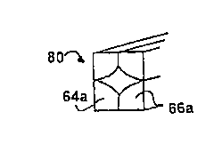
Space-containing wood beam 80 shown in Fig. 19 has been
assembled by arranging two dried units 64a, 66a, made from
half-logs 56, in position so that cut faces 54 and 68a form the
rectangular outer profile of the finished beam and no pattern
cuts 70 are visible thereon. In Fig. 20, the space-containing
beam 80a is identical to beam 80 except that it has been
assembled with sections 64, 66 from half-logs 32 of log 10,
9
RECTIF4ED SHEET (RULE 91)
CA 02267902 1999-04-07
WO 98I15396 PCTlUS97/17765
flattened on four sides; as a result, beam 80a is square
rather than rectangular in cross-section.
Fig. 21 shows vertical assembly 82 of dried units 64a, 66a
made from half-logs 52, 52a, 52b or 52c which might serve as
paneling, fencing, or, when turned 90 degrees, as siding (not
shown). Here, only the surfaces 68a, which have a uniform
planar uncut aspect, are visible in finished products. Units
64, 64a may be held in position and supported in any convenient
way, one of which, transverse plank 84, is shown. Exactly
analogously, vertical assembly 82a of dried units 64, 66 in
Fig. 22 may be used for the same purposes as assembly 82, and
because of the extra flat trimmed surfaces 26 and 28 provided
thereon, is more compact and stronger, with units 64, 66 held
together by adhesive or conventional methods and presenting
smooth planar surfaces 68 to view.
The same structural units as those used for paneling, etc.
in Figs. 21 and 22 are shown in Figs. 23 and 24, respectively,
attached in horizontal array to provide flooring or decking;
thus, in Fig. 23, a plurality of units 64a, 66a joined and
fixed together in a horizontal row, with only planar uncut
surfaces 68a exposed, form floor or deck 86 mounted on support
88; in Fig. 24, units 64, 66 are similarly joined horizontally
and mounted on support 88a to form floor or deck 86a, with
surfaces 68 acting as the floor or deck surface.
Figs. 25 and 26 illustrate the use of the fiber-tension-
relief method described above on pre-cut planks. Intermediate
assembly 90 shown in Fig. 25 comprises identical upper and
lower planks 92 sandwiching therebetween narrower plank 94 in
a symmetrical pile alignedly and adhesively held together, to
be bisected longitudinally along plane 96 to form asymmetric
mirror-image units 98 seen in Fig. 26 adhesively combined with
spacing element 10Q to form beam 1D2. Planks 92 and 94 have
pattern-cuts 70 made on a11 surfaces that will be concealed in
finished beam 102, either before or after intermediate assembly
90 is formed, to minimize or eliminate fiber tension and
consequent warping.
RECTIFIED SHEET (RULE 91 )
CA 02267902 1999-04-07
WO 98l15396 PCT/US97I17765
An assortment of laminated wood structural products
assembled in accordance with this invention of superior
characteristics are illustrated in Figs. 27-36, featuring
tongue-and-grooved planks adhesively secured to asymmetric log
units and; or piles of laminated planks. The resulting siding
or bearns, when erected, form structures of greatly enhanced
strength, stability and weather resistance, eliminating air and
water penetration. Fig. 27 shows siding 104 comprising
asymmetric mirror-image unit 66 (or 64), its flattened surfaces
28 (or 26) being laminated to plank 106, which has
longitudinally extending tongue 108 along its top edge and
groove 110 along its bottom; Fig. 37 has siding 104a with
tongue-and-grooved plank 106 laminated to the opposite surface
68 of unit 66; and beam or siding 112 in Fig. 28 is exactly
like siding 104, except that a second tongue-and-grooved plank
106 has been laminated to unit 66 on its side opposite first
plank 106. Fig. 29 shows siding 114 with laminated vertical
plank pile 116 replacing unit 66 of siding 104, and Fig. 30 has
beam 118 with plank pile 116 replacing section 66 of beam 112.
The double tongue-and-grooved beam 120 of Fig. 31 is
composed of two siding assemblies 104, surfaces 68 of which are
adhesively joined on either side of laminated wood panel 122;
beam 120a of Fig. 32 has siding assemblies 104a replacing two
assemblies l04 of Fig. 31, sandwiching therebetween laminated
wood panel l22. In Fig. 33, beam 124 replaces the two siding
assemblies 104 with laminated plank pile sidings 114 of Fig.
29.
Two alternate methods of producing siding l04 (Fig. 27) are
illustrated in Figs. 34 and 35. In Fig. 34, intermediate
assembly 60 is prepared as described above, then a tongue-and-
grooved plank 106 is laminated on either side to surfaces 26,
28 thereof, creating a beam 126 which may be used as such or
thereafter bisected longitudinally along plane 128 to produce
two mirror-image pieces of siding 104. The alternate method
of Fig. 35, producing beam 126a is identical to that just
described, except that planks 106a without tongues and grooves
are laminated to surfaces 26, 28 of half-log intermediate
11
RECTIFIED SHEET (RULE 91)
CA 02267902 1999-04-07
WO 98I15396 PCTlUS97117765
assembly 60. Beam 126a may be used as such, may have tongue
and-groove cuts made in one or both planks 106a after assembly,
or may be longitudinally bisected along plane 128a to form
identical structural units, which may then be provided with
tongue and groove if desired.
A final illustrative embodiment of this invention is shown
in Fig. 37, wherein composite rectangular beam 130 is shown
comprising asymmetric half-log-derived unit 66 and laminated
vertically stacked plank pile 116 secured adhesively to
laminated wood panel therebetween. It may be noted that beam
130 may be used as is or may have a tongue-and-grooved plank
106 or a plain plank 106a adhesively mounted on either side
thereof.
The methods of this invention are applicable to the wide
variety of wood species available; for example, the choice of
hardwood for floors or decking and such species as cedar and
douglas fir for paneling or siding will be obvious. It also
will be apparent that this invention makes it possible to
utilize small-diameter newer-growth logs more fully instead of
relying on relatively scarce and expensive old-growth timber,
and using wood of lesser quality where not visible.
Best modes now contemplated for practicing this invention
and its concepts have been fully described. It will be evident
to those skilled in the art that modifications, alterations and
substitutions may be made in the details of the procedures and
products disclosed without departing from the spirit and
concepts of this invention, which are limited only by the scope
of the ensuing claims, wherein:
12
RECTIFIED SHEET (RULE 91 )