Note : Les descriptions sont présentées dans la langue officielle dans laquelle elles ont été soumises.
CA 02267916 1999-04-06
WO 98/18735 PCT/ITS97118039
1
APPARATUS AND METHOD FOR REDUCING BREAK
SOURCES IN DRAWN FIBERS
BACKGROUND OF THE INVENTION
FIELD OF THE INVENTION
The present invention relates to a method and
apparatus for drawing a fiber from a bland>, more
particularly, a method and apparatus for drawing an
optical waveguide fiber from a silica-containing blank.
DESCRIPTION OF THE RELATED ART
Optical waveguide fibers (optical fibers) are a
transmission medium used in optical communication systems.
Optical fibers are typically made by well known methods
that involve forming blanks from which the fibers are to
be drawn, storing the blanks in holding ovens, and drawing
fibers from the blanks in draw furnaces. ,
Strength is an important characteristic coptical fibers.
Particulate contaminants on the fiber surface often weaken
the fiber and cause flaw initiation and fiber failure
under tensile loading. Some optical fibers, particularly
those drawn in zirconia (ZrO~) muffle furnaces, break under
low stress due to such contaminants.
SUBSTITdiE SMUT (RULE 28)
CA 02267916 1999-04-06
WO 98/18735 PCT/US97/18039
2
STJNIN'lARY OF THE INVENTION
An object of the present invention is to improve
the strength of fibers.
Another object of the invention is to remove break
sources that cause fibers to break at low stress.
Additional objects and advantages of the invention
will be set forth in part in the description which
follows, and in part will be obvious from the description,
or may be learned by practice of the invention. The
objects and advantages of the invention will be realized
and attained by means of the elements and combinations
particularly pointed out in the appended claims.
As explained more fully below, it has been determined
that breaking optical fibers contain silicon carbide ;SiC)
and silicon nitride (SijN4) refractory contaminants that
cause the fibers to fail at low stress. The present
invention improves the strength of fibers :~y removing the
contaminants through active oxidation during the fiber-
drawing process.
To achieve the objects and in accordance with the
purpose of the invention, as broadly described herein, the
invention provides an improved method of producing a fiber
in a drawing device having a refractory, oxide component
in a drawing portion, comprising the steps of disposing a
blank having a refractory contaminant in the drawing
portion, providing an environment in the drawing portion
that causes active oxidation of the refractory
contaminant, and drawing a fiber from the blank in the
environment.
The invention also provides an improved apparatus for
producing a fiber, comprising a drawing p-=tion that has a
refractory, oxide component and that heats a blank having
a refractory contaminant, a supply device that supplies
gIIBSTITUTE SIIE~' (U~ 2
CA 02267916 1999-04-06
WO 98I18735 PCT/US97/18039
3
gas to the drawing portion to provide an environment in
the drawing portion that causes active oxidation of the
refractory contaminant, and a device for drawing a fiber
from the blank in the environment.
It is to be understood that both the foregoing
general description and the following detailed description
are exemplary and explanatory only and are not restrictive
of the invention, as claimed.
The accompanying drawings, which are incorporated in
and constitute a part of this specification, illustrate an
embodiment of the invention and together with the
description, serve to explain the principles of the
invention.
BRIEF DESCRIPTION OF THE DRAWINGS
FIG. 1 is a sectional view of a preferred
embodiment of a draw furnace according to the present
invention.
FIG. 2 is a sectional view of a holding oven.
DESCRIPTION OF THE PREFERRED EI~~_r;~DIMENT
Reference will now be made in detail to the
presently preferred embodiment of the invention, an
example of which is illustrated in the accompanying
drawings. Wherever possible, the same reference numbers
will be used throughout the drawings to refer to the same
or like parts.
It has been discovered, in connection with the
present invention, that the fibers drawn in conventional
zirconia muffle furnaces that break under low stress
contain silicon carbide and silicon nitride, which are
non-oxide, refractory contaminants. These contaminants
SUBSTITUTE SIlEET ~l~t~ 2~~
CA 02267916 1999-04-06
WO 98/18735 PCT/US97/18039
4
are in the size range typical of airborne particles (less
than 5 ~,m) and attach to the surface of the blank before
or during the drawing process, thus producing a draw
trough or. the surface of the fiber.
It has also been discovered that each contaminant has
an adhered passivation layer of amorphous silica (SiO>)
formed thereon, at least in part, due to the environment
in a conventional zirconia muffle furnace. The
passivation layer is a solid reaction product of passive
oxidation. The passive oxidation mechanisms for silicon
carbide and silicon nitride are represented by the
following formulas:
(2)SiC+(3)O-~ --~ (2)SiO~(s)+(2)CO(g)
Si~N9+ (3) O~ ~ (3) SiO~ (s) +2N~ (g) .
A conventional zirconia muffle furnace has sufficient
oxygen, which is provided by ambient air leaking into the
furnace, to form passivation layers on the contaminants
through passive oxidation.
It has been further discovered, in connection with
the present invention, that these passivation-layered
contaminants act as low-stress break sources for the
optical fibers.
The draw process of the present invention has been
designed to remove these contaminants through active
oxidation. The active oxidation mechanism produces a
gaseous reaction product and thus corrode. the silicon
carbide and silicon nitride contaminants. The active
oxidation mechanisms for silicon carbide and silicon
nitride are represented by the following formulas:
SiC(s)+0~,(g) -~ Si0(g)+CO(g)
Si;N4 (s) + (3/2) 0_ (g) -~ 3Si0 (g)+2N_ (g) .
Thus, by promoting active oxidation, the contaminants can
be removed by corrosion. For example, graphite muffle
furnaces produce fibers that do not contain passivation-
SUBSTIIUtE SlIl~T (RULE 2U~
CA 02267916 1999-04-06
WO 98I18735 PCT/US97/18039 -
layered contaminants because, it is believed, these
furnaces promote active oxidation.
The oxygen concentration and the ten~..erature of the
environment determine whether the passive or active
5 oxidation mechanism will predominate. For example, at a
given temperature, the passive oxidation mechanism
predominates for silicon carbide and silicon nitride when
P,~ > Pco.~;~. and the active oxidation mechanism
predominates when Pa~~"::io > P~_ .
Accordingly, the present invention preferably
promotes active oxidation by providing a low-oxygen
environment in a drawing portion of a draw furnace. In a
preferred mode, a low-oxygen environment is provided by
introducing a reducing gas into the drawing portion hat
will react with oxygen to reduce the oxygen concentration.
The reducing gas can be any gas that reacts readily with
oxygen to reduce oxygen concentration anc thereby create a
benign gas, i.e., a gas that will not react with the blank:
or fiber.
Presently, carbon monoxide (CO) is the preferred
reducing gas. The following experiments illustrate the
effect of carbon monoxide on the environment in the
drawing portion of a zirconia muffle furnace.
Initially, the oxygen concentration was measured
while flowing commercially pure helium (He) through the
muffle at varying rates. The results are shown in Table
1.
SUBSTITUTE SNfE1 ~UL~
CA 02267916 1999-04-06
WO 98/18735 PCT/US97/18039
G
TABLE 1
Heliun. Flow (S.L.P.M.) ~: Oxygen
0.0 21.8G
0.8 2l.70
2.25 l5.00
3.50 2.85
4.50 1.91
5.35 l.55
Next, the oxygen concentration was measured while
flowing a gas consisting of commercially pure helium and
10~; carbon monoxide through the muffle at varying rates.
The results are shown in Table 2.
TABLE 2
Helium and Carbon Monoxide ~ Oxygen
Flow (S.L.P.M.)
3.l9 0.367
4.4 0.0845
4.9 less than 0.00G01
5.6 less than 0.0000l
l4.3 less than 0.0000l
As shown by Tables 1 and 2, use of carbon monoxide as
a reducing gas effectively reduces the oxygen
concentration of the environment in the muffle.
The reduced oxygen environment improves the strength
of fibers drawn in a zirconia muffle furnace, as shown by
tree following experiments.
SUBSTITUTE SI~~E'~' ~~~~S~
CA 02267916 1999-04-06
WO 98/18735 PCT/US97/18039
7
Waveguide blanks were contaminated with a high
concentration of silicon carbide contaminants. The mean
particle size was 6.79 microns and the maximum size was 25
microns. Contaminants were deposited to achieve a
coverage density of greater than 20 per square centimeter
of blank surface.
The seeded blanks were drawn into fiber in a
conventional zirconia muffle furnace. Under conventional
operating conditions (helium purge gas or7~~), the fiber
was difficult to wrap after drawing, yielding lengths of
only 200 to 400 meters between breaks. Strength testing
of approximately 2 kilometers of fiber produced an average
of approximately two low strength breaks per meter. Break
source analysis confirmed that the breaks during wrapping
and strength testing were due to silicon carbide
contaminants blanketed with a layer of amorphous silica.
Next, carbon monoxide was added to the helium purge
gas in the zirconia muffle furnace to reduce the oxygen
concentration in accordance with the equation:
2C0+O_ -j 2C0. When the blanks were loaded into a furnace
environment containing an appropriate amount of carbon
monoxide in addition to the helium purge gas, the draw
performance improved dramatically, yielding lengths of up
to 65 kilometers between breaks. Strength testing of more
than 200 kilometers of fiber and associated analysis of
S~B~TIIUTE SNfEt (~~UIE 26~
CA 02267916 1999-04-06
WO 98/18735 PCT/US97/18039
8
break ends showed that there were no low strength breaks
due to silicon carbide.
Finally, the drawing process was commenced using only
helium as the purge gas and carbon monoxide was added to
the helium midway through the drawing process. Draw
performance improved instantly and dramatically, with the
fiber changing from being unwrappable (without carbon
monoxide) to yielding wrappable lengths of greater than
l00 kilometers (with carbon monoxide).
Similar testing with blanks contaminated with s'licon
nitride contaminants yielded similar results.
As shown by these experiments, the reduced oxygen
environment created by the addition of ca-.ion monoxide
creates a passive to active oxidation transition. The
15, contaminants corrode away due to active oxidation and do
not form break sources.
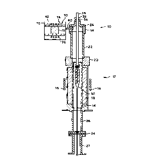
A preferred embodiment of a draw furnace according to
the present invention is shown in FIG. 1 and is designated
generally by the reference numeral 10. In accordance with
the invention, draw furnace 10 includes a drawing portion
that has a refractory, oxide component and that heats a
blank having a refractory contaminant to a fiber drawing
temperature, and a supply device that supplies gas to the
drawing portion to provide an environment in the drawing
portion that causes active oxidation of the refractory
contaminant.
~iBSTITII'~ ~NEE~' (I~~ ~~~
CA 02267916 1999-04-06
WO 98/18735 PCT/US97118039 -
9
As shown herein, the drawing portion 12 includes a
zirconia muffle 14, which is a refractory, oxide
component. The zirconia muffle distributes heat generated
b~% a heating coil 16 that has passed through insulation
18. In the present invention, the integri~y of the
environment in the drawing portion has been improved by
providing a high temperature ceramic glue (CERAMABOND
#503, Armco Products) that forms a gas-tight seal between
beaker top 20 and upper muffle extension 22, and a flat,
i0 closed-cell silicone gasket 24 (Material Nc. 7204,
Groendyk Mfg. Co.) that forms a gas-tight seal between
lower muffle extension 26 and Elmer tube 27.
A blank support rod 28 holds blank 30 in drawing
portion 12. An O-ring 32 forms a seal between rod 28 and
sealing member 39, which is formed of metallic foil or the
like. Sealing member 34 connects to end ,ap 36, which
itself is connected to annular member 38.
As shown herein, the supply device includes pipe 40
that extends through annular member 38. Pipe 40 is
connected to gas supply 42 and supplies gas from gas
supply 42 to the drawing porti.0l1 12, thereby provid,~ng an
environment in drawing portion 12 that causes active
oxidation of the refractory contaminant and inhibits
passive oxidation.
Pipe 40 preferably flows gas through muffle 14 at a
cor:stant flow rate of 2 to 5 standard lit~.vs per minute.
SUBSTITUTE SNEET (RULE 2i~
CA 02267916 1999-04-06
WO 98/18735 PCT/US97/18039 -
The flow rate can be altered based on factors such as the
flow rate needed to maintain control of fiber attributes.
Preferably, the gas supply 42 supplies a purge gas
containing a reducing gas that reacts with oxygen to lower
5 the oxygen concentration of the environment of the drawing
portion. More preferably, the purge gas consists of
helium and carbon monoxide. Carbon monoxide reacts with
oxygen to produce carbon dioxide (CO,), tnus reducing the
oxygen concentration in the environment.
10 When using the preferred purge gas, the gas supply 42
can be, for example, a reservoir of both helium and carbon
monoxide or separate reservoirs of helium and carbon
monoxide, the outputs of which are combined before or as
they enter the draw furnace. In view of the toxic nature
c~ carbon monoxide, however, it may be preferable to use
are external furnace that produces carbon monoxide by
reaction and, therefore, renders unnecessary a reservoir
~~r carbon monoxide.
Fig. 1 diagrammatically illustrates such an external
furnace 70. The external furnace 70 includes a reactive
material 72 that reacts with at least a gas of a non-toxic
gas mixture (provided by unillustrated gas reservoir(s))
to produce carbon monoxide. The reactive material 72 can
be a porous carbon or graphite material (such as a carbon
honeycomb substrate manufactured by Corning Incorporated,
SUBSTITUTE SHEET (RULE 2P~
CA 02267916 1999-04-06
WO 98/18735 PCT/US97/18039
11
e.g., part no. K2225) through which the non-toxic gas
mixture can be passed.
The non-toxic gas mixture preferably contains helium
and a reactive gas. The reactive gas, which can be, for
example, carbon dioxide or oxygen, will react with the
carbon material 72 to produce carbon monoxide. The
desired amount of carbon monoxide (preferably about 2'.= by
volume) can be produced by manipulating the reactive gas
concentration and the reaction temperature (the external
furnace 70 preferably operates at atmosph~.~-ic pressure).
When the reactive gas is carbon dioxide, the
equilibrium reaction is:
CO~ + C = 2C0.
This reaction proceeds to near completion (more than 95'~
conversion) at 1000~C and atmospheric pressure.
When the reactive gas is oxygen, two competing
reactions occur:
0- + C = CO-
0~ + 2C = 2C0
The reaction producing carbon monoxide is favored at high
temperatures and low oxygen pressures. At l000~C and
atmospheric pressure (P~ < 0.05), thermodynamic
equilibrium predicts that the CO:CO~ ratio should be
greater than 100:1. This ratio may be decreased if gas
flow rates are fast enough to cause an incomplete
SUBSTITUTE SHEET (RUSE 2B)
CA 02267916 1999-04-06
WO 98/18735 PCT/US97/18039
12
reaction. However, the typical flow rate for a zirconia
draw furnace (4.5 standard liters per min;.:e) is slow
enough to ensure that the reaction is not kinetically
limited. This is true when either carbon dioxide or
oxygen is the reactive gas.
Since the preferred non-toxic gas mixtures will have
to be heated to produce the desired amount of carbon
monoxide, the external furnace 70 will preferably include
a heating device. The heating device can include a muffle
74 that distributes heat generated by a heating coil 76 to
heat the gas to a preferred temperature of l000~C. The
muffle 74 may be made with alumina, but can be any
material that will withstand relatively high temperatures
and will not react with gas flowing through the external
furnace 70.
Accordingly, the external. furnace 7U can provide a
purge gas containing carbon monoxide without the risks
inherent in maintaining a reservoir of carbon monoxide.
The purge gas preferably contains only as much carbon
monoxide as is necessary to provide an oxygen
concentration that promotes active oxidation. The amount
of carbon monoxide required can be theoretically
determined by, for example, calculating tO - amount of
carbon monoxide required to cause P," (after introducing
carbon monoxide) to be greater than Po~ (before introducing
carbon monoxide). Present zirconia muffle furnaces
SUBSTITUTE BNNEET CRU~~ 2U~
CA 02267916 1999-04-06
WO 98I18735 PCTIUS97118039 -
13
require approximately 2 to 5'<'~ carbon monoxide in the purge
gas to meet this requirement. Also, the necessary amount
o~ carbon monoxide can be determined by measuring the
oxygen concentration in the drawing portion and adjusting
the amount of carbon monoxide until the appropriate oxygen
concentration is achieved. It is presently contemplated
that a delta-F electrolyte detector can be used to measure
the oxygen concentration in the drawing portion.
A conventional drawing mechanism (not shown) can be
used to draw a fiber from the bland; in the environment in
the drawing portion. A slow drawing speed is better for
ablating contaminants, but the particular drawing speed
chosen can also depend on other factors such as the
furnace type and the product type.
A holding oven has been designed to .,-prove the
e~ficiency of the above-described process. This holding
oven and its use in conjunction with a drawing furnace are
disclosed and claimed in a U.S. Application by J.E.
Dickinson, D.J. Wissuchek, J.A. Snipes, J.L. Dunn, B.W.
Reding, and G.S. Glaesemann and entitled Apparatus and
Method for Inhibiting Passive Oxidation of a Contaminant
ir: a Biank Used for Drawing an Optical Waveguide Fiber
(Attorney docket no. A-8614), filed concurrently herewith,
the disclosure of which is hereby incorporated by
reference.
SUBSTIME BNEET (R0~ 2~
CA 02267916 1999-04-06
WO 98/18735 PCT/US97/18039
14
A passivation layer formed on a contaminant before a
blank enters the draw furnace may inhibit corrosion of the
contaminant by active oxidation ii: the drawing process.
The passivation layer hinders the reaction by creating a
diffusive barrier for oxidation reactants and products.
For example, the reaction rate for the corrosion of
silicon carbide and silicon nitride is governed by the
rate of diffusion of carbon monoxide or nitrogen through
the passivation layer.
Thus, for blanks having a contaminant with a
passivation layer, the draw process must supply sufficient
time under active oxidation conditions to ablate the
contaminant with its passivation layer. If the
passivation layer is sufficiently thick, the drawing
process may not fully remove the contaminant or may remove
it so slowly tlat the process is not practical.
The improved holding oven inhibits passive oxidation
of contaminants and prevents the formation of a
passivation layer. An embodiment of the improved holding
oven is shown in FIG. 2 and is designated generally by
reference numeral 50. Holding oven 50 is a conventional
holding oven that has been modified to provide an
environment that inhibits passive oxidation of
contaminants. Holding oven 50 includes a compartment for
storing a blank, and a supply device that supplies gas to
the compartment that provides an environment in the
SUBSTITUTE S!lEET (UU~E ~U~
CA 02267916 1999-04-06
WO 98/18735 PCT/US97/18039 -
compartment that inhibits passive oxidation of a
refractory contaminant of the blank.
As shown herein, compartment 52 for storing blank 30
includes muffle 54 that is centered by centering ring 56
5 and top seal 58. The top of compartment 52 is covered by
top seal 58 and cover 60. A handle 62 extends through
cover 60 to hold blank 30. Heaters and insulation 64
maintain the compartment 52 at an appropriate temperature,
preferably about 950~C.
10 In the form shown, the supply device includes a pipe
66 that extends into compartment 52 throw n top seal 58.
Pipe 66 is connected to a gas reservoir 68 and supplies
the gas from reservoir 68 to compartment 52, thereby
creating an environment that inhibits passive oxidation of
15 the contaminant.
The gas in reservoir 68 preferably is commercially
pure argon (Ar), which has an oxygen concentration of less
than 0.1 part per million (ppm). Argon provides a clean
environment by preventing ether impurities from getting
onto the blank. Also, argon weighs more than air and,
therefore, will remain in an uncovered cora:artment. Other
benign gases can be selected, such as commercially pure
nitrogen (N~), which has an oxygen concentration of
approximately 80 ppm.
SBBBTI1UT~ SNElT (BI!!E ~~
CA 02267916 1999-04-06
WO 98/i8735 PCT/LTS97/18039 -
1G
The argon gas is preferably flowed through the
compartment at a constant flow rate of 0.5 to 1.0 standard
liters per minute.
It will be apparent to those skilled in the art that
various modifications and variations can be made in the
method and apparatus of the present invention without
departing from the scope or spirit of the invention. For
example, although a preferred embodiment has been
described with reference to the drawing of optical
waveguide fibers from silica-containing blanks, certain
aspects of the invention may be applied to the drawl?zg of
fibers of other suitable materials. As a further example,
although the invention has been described .pith reference
t~silicon carbide and silicon nitride contaminants, the
invention may be used for other oxidizable, refractory
ceritaminants, such as tungsten carbide.
Other embodiments of invention will be apparent to
those skilled in the art from consideration of the
specification and practice of the invention disclosed
herein. It is intended that the specification and
examples be considered as exemplary only, with a true
scope and spirit of the invention being indicated by the
following claims.
~5
SUBSTITUTE SHEET (RULE 2B)