Note : Les descriptions sont présentées dans la langue officielle dans laquelle elles ont été soumises.
' CA 02268207 1999-04-O1
FUEL VAPOR MANAGEMENT SYSTEM
BACKGROUND OF THE INVENTION
Field of the Invention
This invention relates to the field of reducing
the amount of fuel vapor emitted from a vehicle fuel
system. More specifically, the present invention relates
l0 to condensing fuel from a fuel vapor mixture and
returning the condensate to the fuel tank. The present
invention also relates to reducing the amount of fuel
vapor emitted during vehicle diurnal cycles.
Disclosure information
Fuel vapors generated in the fuel tank are
managed by the vehicle evaporative control system. The
evaporative control system is designed to provide for the
consumption and storage of vapors. Vapors are typically
conveyed to the engine inlet manifold for consumption
when the engine is operating and to the evaporative
emissions carbon canister for temporary storage when the
engine is not operational. As maximum allowed emissions
standards for unburned hydrocarbons decrease, vapor
storage canisters have become larger to accommodate a
greater amount of vapor. Optimum system design seeks to
minimize the canister volume by protecting against fuel
tank vapor generation transients along with aggressive
engine purging strategies.
The storage requirements of the evaporative
control system require large volume canisters with the
capability to store the fuel vapors that are generated
-1-
CA 02268207 1999-04-O1
when the engine is not running. Two vapor generation
transients contribute the majority of the vapor delivered
to the canister.
The first transient occurs during diurnal
cycles. Diurnal cycles produce hydrocarbon evaporative
emissions resulting from the daily cycling of ambient
temperatures on the vehicle system, also known as
breathing losses. Vapors produced during diurnal heating
are directed into the carbon canister. During the
diurnal cooling, air is drawn into the evaporative
emissions system through the atmospheric vent on the
carbon canister in order to offset the vapor volume
reduction in the fuel tank and prevent a partial vacuum.
The second major transient occurs during the
refueling process. Vapors displaced by the incoming
liquid are directed into the canister using the induced
pressure in the fuel tank. Design considerations for
refueling encourage minimization of the distance between
the canister and the fuel tank. Therefore, most
2o canisters are packaged on the underbody near the vehicle
fuel tank.
The use of devices to condense fuel vapors
during refueling is not new. U.S. Patent 5,636,668, to
Thompson, which is assigned to the assignee of the
present invention, discloses a vapor recovery system
which cools fuel entering the filler pipe of a vehicle
using a heat exchanger powered by the vehicle's
electrical system.
U.S. 5,255,735, to Rahava et al, describes an
in-tank fuel vapor condenser in combination with a
electric cooler to main the condensate in a liquid state.
Such condensers are undesirable because of the additional
electrical power requirements.
- 2-
CA 02268207 1999-04-O1
U.S. Patent 4,304,206, to Hall, discloses a
fuel vapor ventilation system with a fuel condensate trap
located between the fuel tank and the canister. Unlike
the evaporative control system in the present invention,
which uses the cooler temperature of the fuel entering
the tank for heat exchange, the Hall patent relies on
condensation generation from natural exposure of the fuel
vapor to ambient temperature between the fuel tank and
the canister.
It is an object of the present invention to
provide a simple and inexpensive method of reducing the
amount of vapor mass emitted from an automobile fuel
cank.
It is an advantage of the present invention
that fuel vapor will be condensed during vehicle
refueling without an electrical or externally powered
device.
It is a further advar~tage of the present
invention that the mass of fuel vapor pumped to the
canister will be reduced during diurnal cycles.
Other features, objects and advantages of the
present invention will become apparent to the reader of
this specification.
SUN~ARY OF THE INVENTION
A fuel vapor emission control system for an
automobile, according to the present invention, includes
a filler pipe mounted between a fuel entry port and a
fuel tank inlet; a filler cap; a fuel tank which receives
fuel from the filler pipe; and a vapor tube for
conducting fuel vapor from one or more tank rollover vent
valves located on a wall of the fuel tank, with said
-3-
' CA 02268207 1999-04-O1
vapor tube passing through (or in thermal contact with)
the fuel filler pipe, such that fuel entering the fuel
tank through the filler pipe impinges upon the vapor tube
and absorbs heat from fuel vapor flowing within the vapor
tube.
The present system further includes a reservoir
connected with the vapor tube for collecting condensed
fuel, with said reservoir further comprising a return
line for returning said condensate to said fuel tank and
l0 a feed line extending between the vapor tube and an on-
board refueling vapor recovery (ORVR) carbon canister,
with the feed line conveying uncondensed displaced vapor
to the carbon canister.
The invention also ~.ncludes a method for
IS reducing the amount of fuel vapor entering an ORVR carbon
canister during vehicle refueling, including the steps of
passing relati~-ely cooler fuel from a fuel storage tank
over a condenser located in a fuel filler pipe
operatively connected with a vehicle fuel tank; passing
20 vapor displaced by fuel entering the fuel tank through
said condenser, condensing liquid fuel from said vapor;
co~lecting condense: liquid fuel in a reservoir; and
returning said liquid fuel from said reservoir to the
fuel tank.
25 The invention also includes a second method for
reducing the amount of fuel vapor discharged by an
automotive fuel tank during a twenty-four hour diurnal
heating and cooling cycle, including the steps of, during
a first heating portion of the cycle, allowing fuel vapor
30 to pass through a rollover vent valve in the fuel tank
and then through a check valve and into a vapor storage
canister; during a first cooling portion of the cycle,
allowing the check valve to close in response to a
-4-
' CA 02268207 1999-04-O1
lowering of vapor pressure within the tank as the
temperature is reduced thereby creating a partial vacuum
in the fuel tank; reducing the volume of the fuel tank in
response to said vacuum; and preventing the release of
fuel vapor during a subsequent heating portion of the
cycle, unless the fuel tank temperature exceeds the
temperature of the first heating portion, by permitting
fuel vapor to expand the volume of the fuel tank.
The present invention reduces the volume
required for vapor storage by reducing the mass of vapor
emitted from the fuel tank. Reducing the volume of the
vapor storage canister reduces vehicle cost and .improves
packaging.
BRIEF DESCRIPTION OF THE DRAWINGS
The presently preferred embodiment of the
invention is disclosed in the following description and
in the accompanying drawings, wherein:
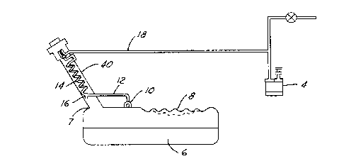
FIG 1. is a partial schematic of an evaporative
control system assembly according to the present
invention.
FIG 2. is a sectional representation of vapor
tube located in a filler pipe and connected to a filler
cap check valve according to the present invention.
FIG 3. is similar to FIG 2., but shows the
sequential removal of the filler cap with built-in check
valve.
DETAILED DESCRIPTION OF PREFERRED EMBODIMENT
Referring to FIG. 1, an evaporative control
system, according to the present invention, includes fuel
-5-
' CA 02268207 1999-04-O1
tank 6 with flexible portion 8 in one of the walls. Vapor
tube 12 exits tank 6 from rollover vent valve 10 and passes
through filler pipe 40. As illustrated in FIG. 2, vapor
condensing tube 14 is connected to a port 33 which aligns
with the inlet of check valve 34 which is located in filler
cap 24. The exit from the check valve 38 is connected to
feed line 18 which is connected to evaporative emissions
canister 4 (FIG. 1) and the engine in conventional fashion.
As used herein, "evaporative emissions carbon canister"
means a regular running loss vapor canister as well as an
onboard vapor recovery ORVR) canister. Those skilled in
the art will appreciate that such canister may include
either carbons or other hydrocarbon adsorbing/desorbing
agents.
Filler pipe 40 houses 'vapor condensing tube 14,
generally between the inlet to the check valve in the
filler cap 34 and vapor line 12 from rollover valve 10.
Vapor condensing tube 14 is oriented in filler pipe 40 to
facilitate heat exchange between the fuel being dispensed
into filler pipe 40 as it flows from filler pipe inlet 37
to filler pipe outlet 41 and fuel tank 6. Vapor
condensing tube 14 is preferably shaped to maximize heat
exchange as the entering fuel impinges upon vapor
condensing tube 14.
During refueling, when filler cap 24 is removed
and fuel is pumped into filler pipe 40, vapor will be
displaced from tank 6 and pass through rollover valve 10
and through vapor condensir_g tube 14 in filler pipe 40.
Usually, fuel enters filler pipe 40 from an underground
storage tank at a much lower temperature than the fuel
vapor in tank 6. The cold fuel entering filler pipe
inlet 39 will impinge on the walls of the vapor
condensing tube 14, thus cooling and condensing some of
-6-
CA 02268207 1999-04-O1
the fuel vapor leaving rollover vent valve 10. This
cooling of the fuel vapor reduces its volatility and
causes fuel vapors emitted from fuel tank 6 to be
condensed as the cooler liquid passes through filler pipe
40. The p<:.rtion of the fuel vapor which condenses will
enter reservoir drain 16 and reenter filler pipe 40
returning into fuel tank 6 as liquid fuel. The portion
of fuel vapor which does not condense will continue
through vapor condensing tube 14, through check valve 36,
l0 and enter canister feed line 18 which connects to carbon
canister 4 in conventional fashion. The present
invention will reduce the amount of fuel vapor which the
carbon canister 4 would be required to store as the
result of a refueling event.
During a series of diurnal cycles, the vapor in
fuel tank 6 is repeatedly heated and cooled, thus causing
expansion and contraction of the vapor. During an
initial heating cycle, fuel vapor will be forced through
rollo~Ter vent valve 10, through vapor tube 12, through
condensing tube 14 and check valve 34 in filler cap 24,
and into carbon canister 4. When fuel vapor in tank 6
experiences a cooling cycle, the check valve 36 will
prevent air from being drawn into the system and will
cause a partial vacuum to exist in tank 6. This partial
vacuum will cause flexible portion 8 of tank 6 to deform,
thus reducing the magnitude of the vacuum and the volume
of the fuel tank. Flexible portion 8 is a substantial
portion of one wall of the tank 6 and is integrated into
the wall. One embodiment in a plastic tank might consist
of a corrugated diaphragm molded into one wall. When the
fuel vapor begins another heating cycle, fuel tank 6 will
again expand and allow flexible portion 8 of tank 6 to
return to its original shape and volume. Fuel tank 6
- CA 02268207 1999-04-O1
will not vent any fuel vapor to carbon canister 4 during
this heating cycle unless the temperature exceeds the
temperature achieved during the initial heating cycle.
Thus, the cumulative volume of fuel vapor which exits the
fuel tank 6 over several diurnal cycles will be
significantly reduced.
FIG.3 is a sectional representation of the
condensing vapor tube 14 and filler cap 24 and
demonstrates a sequential embodiment of a portion of a
system according to the present invention during removal
of filler cap 24 and check valve 36 from the filler pipe
40. The present invention uses check valve 36, to
control pressure differentials within the system. During
removal of filler cap 24, pressure differentials must be
dissipated to prevent fuel from rapidly exiting filler
pipe 40. FIG 3a illustrates the system with filler cap
24 in fully closed position and internal pressure is
greater than atmospheric pressure. Referring now to FIG
3h, a:~ filler cap 24 is removed, the check valve 36 is
moved out of the way and face seal 30 moves away from
seat 31 allowing vapors to pass between the vapcr_
condensing tube 14 and feed line 18, thus equalizing the
pressure between vapor tube 14 and feed line 18.
Referring now to FIG 3c, as filler cap 24 is further
removed, O-ring seal 32 moves away from seat 33 and
allows the pressure to be equalized between vapor
condensing tube 14 and filler pipe 40. Referring now to
FIG 3d, as filler cap 24 is further remoT,red, O-ring 28,
located above check valve exit 38, will move away from
seat 39 after the pressure has been dissipated and
equalized to external atmosphere.
_ g_
- CA 02268207 1999-04-O1
The above description is of a preferred
embodiment of the present invention which is intended to
provide an enabling description of the present invention.
The broad scope of the present invention should be
construed by reference to the followincJ. claims
-9-