Sélection de la langue

Search

Sommaire du brevet 2268416 

Énoncé de désistement de responsabilité concernant l'information provenant de tiers

Une partie des informations de ce site Web a été fournie par des sources externes. Le gouvernement du Canada n'assume aucune responsabilité concernant la précision, l'actualité ou la fiabilité des informations fournies par les sources externes. Les utilisateurs qui désirent employer cette information devraient consulter directement la source des informations. Le contenu fourni par les sources externes n'est pas assujetti aux exigences sur les langues officielles, la protection des renseignements personnels et l'accessibilité.

Disponibilité de l'Abrégé et des Revendications

L'apparition de différences dans le texte et l'image des Revendications et de l'Abrégé dépend du moment auquel le document est publié. Les textes des Revendications et de l'Abrégé sont affichés :

  • lorsque la demande peut être examinée par le public;
  • lorsque le brevet est émis (délivrance).
(12) Demande de brevet: (11) CA 2268416
(54) Titre français: ETRANGLEUR DE TUYAU SOUPLE
(54) Titre anglais: HOSE STRANGLER
Statut: Réputée abandonnée et au-delà du délai pour le rétablissement - en attente de la réponse à l’avis de communication rejetée
Données bibliographiques
Abrégés

Désolé, les abrégés concernant le document de brevet no 2268416 sont introuvables.

Revendications

Note : Les revendications sont présentées dans la langue officielle dans laquelle elles ont été soumises.

Désolé, les revendications concernant le document de brevet no 2268416 sont introuvables.
Les textes ne sont pas disponibles pour tous les documents de brevet. L'étendue des dates couvertes est disponible sur la section Actualité de l'information .

Description

Note : Les descriptions sont présentées dans la langue officielle dans laquelle elles ont été soumises.

CA 02268416 1999-04-20
1
HOSE STRANGLER
Field of the invention
The present invention relates to hose stranglers.
Description of the prior art
A hose strangler is used extensively in forestry and municipal fire fighting
applications. The fundamental use of a hose strangler is to momentarily stop
the
flow of water through the hose in order to change a nozzle, repair a hose, add
hose length, change or add adapters, etc. This can be done without having to
stop a pump and engine, and provides a fast and easy way to make the above
changes in an emergency situation.
Figures 1, 2, 3 and 4 are representative of the various existing hose
stranglers presently available. Fig. 1 shows a flat strangler, whereas Fig. 2
shows
a strangler with a V-shape. The V-shape strangler was developed to improve the
flat hose strangler, specifically to reduce the problem of hose pinching
(snake eye)
and strangler slippage. Figs. 3 and 4 show other types of available hose
stranglers.
Although it is an industry accepted safe strangler, the existing stranglers do
have a problem when the user wants to remove the strangler from the hose.
While the strangler is closed on the hose, water pressure is building up on
one
side of the strangler, whereas on the other side, water pressure is near zero.
Slippage is then possible and makes the removal of the strangler a hazardous
operation. More specifically, it has been noted that slippage occurs mostly
when
the operator is opening the strangler. At this time, there is not maximum
compression on the hose to firmly maintain the strangler in place.
Accordingly,
there is a risk, when opening the strangler, that the pressure build up will
tear the
strangler from the user's hand and fly off. One solution to this problem has
been
to propose rubber shoes or pads, but this does not completely resolve the
issue.

CA 02268416 1999-04-20
2
Slippage is also a concern when dealing with hoses made with aramid
fibres, since these types of hoses are more slippery, and the risk of injury
is
greater.
Summary of the invention
It is thus an object of the invention to propose a hose strangler which
considerably reduces the risk of slippage when the strangler is opened.
In accordance with the invention, this object is achieved with a hose
strangler comprising:
a lower arm having two opposite ends and a concave portion near a first
opposite end;
an upper arm having two opposite ends and a convex portion near a first
opposite end, the convex portion mating with the concave portion of the lower
arm
when the hose strangler is in a closed position, the second opposite end of
the
upper arm being pivotally connected to the second opposite end of the lower
arm,
a middle arm pivotally fastened to the upper arm, having a link pin for
engagement with said lower arm in order to secure said upper arm and said
lower
arm together when said hose strangler is in a closed position;
characterised in that the upper arm further includes means for opening an
area between the concave and convex portions when the hose strangler is in the
closed position, in order to permit equalisation of pressure on each side of
the
strangler.
Brief description of the drawings
The present invention and its advantages will be more easily understood
after reading the following non-restrictive description of preferred
embodiments
thereof, made with reference to the following drawings in which:
Figures 1 to 4, identified as prior art, illustrate prior hose stranglers,
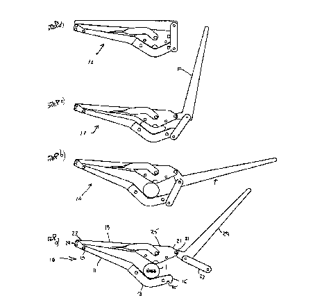
Figure 5 shows the steps for strangling a hose with a hose strangler
according to the invention;

CA 02268416 1999-04-20
3
Figure 6 shows the steps for unstrangling a hose with the hose strangler of
Fig. 5; and
Figure 7 shows a detailed view of the means for opening an area between
the concave and convex portions according to the invention.
Description of a areferred embodiment of the invention
Figures 5 and 6 show the basic components of a hose strangler according
to the invention.
The hose strangler 10 includes a lower arm 11 having two opposite ends
15, 17 and a concave portion 13 near a first opposite end 15; an upper arm 19
having two opposite ends 21, 23 and a convex portion 25 near a first opposite
end
21, the convex portion 21 mating with the concave portion 13 of the lower arm
11
when the hose strangler is in a closed position, the second opposite end 23 of
the
upper arm 19 being pivotally connected to the second opposite end 17 of the
lower
arm 17 by a pivot 27; a middle arm 29 pivotally fastened to the upper arm 19
at a
pivot point 31, having a link pin 33 for engagement with a notch 35 in the end
15 of
the lower arm 11 in order to secure said upper arm and said lower arm together
when said hose strangler 10 is in a closed position.
The invention concerns means for opening an area between the concave
and convex portions 13, 25 when the hose strangler is in the closed position,
in
order to permit equalisation of pressure on each side of the strangler.
Preferably, as shown in Fig. 7, the means for opening an area are
preferably located on the upper arm 19. The means consist of an indent 41
where
would have been the apex of the convex portion 25 were it not for the
invention.
Pivotally attached to the convex portion 25 (and preferably sandwiched between
two identical pieces forming the convex portion, only one of which is shown in
Fig.
7) is a lever 43 and a cam arm 45. The lever 43 can be pivoted between an open
and closed positions. Figure 7a corresponds to the closed position and Fig. 7c
corresponds to the open position. As can be seen, the cam arm 45 is further
provided with a cam 47 which serves to press against the lever 43. When the
lever 43 is in the open position, so is the cam arm 45. This is the position
that

CA 02268416 1999-04-20
4
permits water pressure equalisation. When the lever is in the closed position,
the
cam arm is also in the closed position, and the cam pushes against the lever
43 to
block indent 41.
In use, the strangler is opened (see Fig. 5a) and the hose 1 is installed
between the upper and lower arms 19, 11. The middle arm 29 is rotated until it
is
possible to engage the side link 33 into the notch 35 (Fig. 5b). The middle
arm 29
is then gradually rotated towards the pivot point 27 in order to strangle the
hose
(Figs. 5c and 5d). At 5d, the strangler is closed and secured, and
modifications of
the hose or nozzle are possible on the side without water pressure (note:
during
this procedure, the means are closed).
When the necessary modifications have been made, it is now necessary to
open the strangler - at this point, water pressure is at a maximum on one side
of
the strangler and almost zero on the other side.
Referring now to Fig. 6, the cam arm 45 is rotated to its open position (Fig.
6b). This allows the lever 43 to rise due to the water pressure. This permits
the
water to flow through the strangler and gradually equalises the water pressure
on
both sides of the strangler. Once the pressure has been sufficiently
equalised, the
middle arm 19 is pivoted outwardly to disengage the link 33 from the notch 35,
which then enables the strangler 10 to be opened. This last step is done
safely
without risk of injury since the water pressure is evenly distributed on both
sides of
the strangler, and therefore there is no risk of slippage.
Although the present invention has been explained hereinabove by way of a
preferred embodiment thereof, it should be pointed out that any modifications
to
this preferred embodiment within the scope of the invention is not deemed to
alter
of change the nature and scope of the present invention.

Dessin représentatif
Une figure unique qui représente un dessin illustrant l'invention.
États administratifs

2024-08-01 : Dans le cadre de la transition vers les Brevets de nouvelle génération (BNG), la base de données sur les brevets canadiens (BDBC) contient désormais un Historique d'événement plus détaillé, qui reproduit le Journal des événements de notre nouvelle solution interne.

Veuillez noter que les événements débutant par « Inactive : » se réfèrent à des événements qui ne sont plus utilisés dans notre nouvelle solution interne.

Pour une meilleure compréhension de l'état de la demande ou brevet qui figure sur cette page, la rubrique Mise en garde , et les descriptions de Brevet , Historique d'événement , Taxes périodiques et Historique des paiements devraient être consultées.

Historique d'événement

Description Date
Inactive : CIB de MCD 2006-03-12
Réputée abandonnée - omission de répondre à un avis exigeant une traduction 2001-07-26
Demande non rétablie avant l'échéance 2001-07-25
Inactive : Morte - Aucune rép. à lettre officielle 2001-07-25
Inactive : Incomplète 2001-04-26
Réputée abandonnée - omission de répondre à un avis sur les taxes pour le maintien en état 2001-04-20
Demande publiée (accessible au public) 2000-10-20
Inactive : Page couverture publiée 2000-10-19
Inactive : Renseign. sur l'état - Complets dès date d'ent. journ. 2000-08-31
Inactive : Abandon. - Aucune rép. à lettre officielle 2000-07-25
Inactive : CIB en 1re position 1999-05-25
Inactive : Certificat de dépôt - Sans RE (Anglais) 1999-05-11
Demande reçue - nationale ordinaire 1999-05-10

Historique d'abandonnement

Date d'abandonnement Raison Date de rétablissement
2001-07-26
2001-04-20

Historique des taxes

Type de taxes Anniversaire Échéance Date payée
Taxe pour le dépôt - générale 1999-04-20
Titulaires au dossier

Les titulaires actuels et antérieures au dossier sont affichés en ordre alphabétique.

Titulaires actuels au dossier
WILDFIRE FIRE EQUIPMENT INC.
Titulaires antérieures au dossier
LEN HROMINCHUK
Les propriétaires antérieurs qui ne figurent pas dans la liste des « Propriétaires au dossier » apparaîtront dans d'autres documents au dossier.
Documents

Pour visionner les fichiers sélectionnés, entrer le code reCAPTCHA :


Pour visualiser une image, cliquer sur un lien dans la colonne description du document (Temporairement non-disponible). Pour télécharger l'image (les images), cliquer l'une ou plusieurs cases à cocher dans la première colonne et ensuite cliquer sur le bouton "Télécharger sélection en format PDF (archive Zip)" ou le bouton "Télécharger sélection (en un fichier PDF fusionné)".

Liste des documents de brevet publiés et non publiés sur la BDBC .

Si vous avez des difficultés à accéder au contenu, veuillez communiquer avec le Centre de services à la clientèle au 1-866-997-1936, ou envoyer un courriel au Centre de service à la clientèle de l'OPIC.

({010=Tous les documents, 020=Au moment du dépôt, 030=Au moment de la mise à la disponibilité du public, 040=À la délivrance, 050=Examen, 060=Correspondance reçue, 070=Divers, 080=Correspondance envoyée, 090=Paiement})


Description du
Document 
Date
(aaaa-mm-jj) 
Nombre de pages   Taille de l'image (Ko) 
Abrégé 2000-10-19 1 2
Revendications 2000-10-19 1 2
Description 1999-04-19 4 183
Dessins 1999-04-19 7 153
Dessin représentatif 2000-10-03 1 12
Certificat de dépôt (anglais) 1999-05-10 1 165
Demande de preuve ou de transfert manquant 2000-04-24 1 109
Courtoisie - Lettre d'abandon (lettre du bureau) 2000-08-28 1 171
Rappel de taxe de maintien due 2000-12-20 1 112
Courtoisie - Lettre d'abandon (taxe de maintien en état) 2001-05-17 1 182
Courtoisie - Lettre d'abandon (incompléte) 2001-08-15 1 172
Correspondance 1999-05-12 1 35
Correspondance 2001-04-25 1 18