Note : Les descriptions sont présentées dans la langue officielle dans laquelle elles ont été soumises.
CA 02270108 1999-04-27
WO 98119519 PCT/SE97/01845
A teatcup Liner and a method of manufacturing a teatcup liner
BACKGROUND OF THE INVENTION AND PRIOR ART
The present invention refers to a teatcup liner intended for being
mounted in a teatcup shell, comprising
a tubular head portion, which forms a passage arranged to
receive a teat and extending between a first and a second axial end
of the tubular head portion, and which comprises an annular lip,
extending radially inwardly from the tubular head portion in the
mounted as well as the non-mounted state of the teatcup liner,
a tubular shaft portion, extending from the second axial end of
the head portion, and
a member arranged to provide a radiaily outwardly directed
pretension in the lip in the mounted as well as the non-mounted
state of the teatcup liner. Moreover, the invention refers to a method
of manufacturing a teatcup Liner.
US-A-4 324 201 discloses a type of teatcup liner which comprises a
tubular upper part forming a passage for receiving a teat. An
annular lip extends radially inwardly from the tubular upper part and
defines a circular aperture for the teat. A tubular shaft portion
extends downwardly from the upper part to abut the teat being
introduced therein. This type of teatcup liner is intended to be
mounted in a teatcup shell by simply being introduced therein. In
connection with the mounting, no real deformation of the teatcup
liner takes place. When the rubber material of such teatcup liners
ages, the lip to enclose the teat will be weakened. This means that
the teatcup liner already at an initial stage, i.e. when it is applied to
the teat, will crawl upwardly on the teat, which may result in a
hindering influence to the milk flow. Furthermore, a weakened lip
means that the slip frequency, i.e. the inlet suction of air between
SUBSTITUTE SHEET (RULE 26)
p lil
CA 02270108 1999-04-27
WO 98/19519 PCTISE97101845
2
the teatcup liner and the teat, increases. This type of teatcup liner is
also disclosed in US-A-4 745 881.
US-A-4 116 165 discloses another type of teatcup liner achieving its
effective shape first when it is mounted in a teatcup shell. In its most
basic embodiment, this type of teatcup liner merely is comprised by
a hose portion. The teatcup liner disclosed comprises in a mounted
state a tubular upper part forming a passage for receiving a teat. An
annular lip extends radially inwardly from the tubular upper part and
defines a circular aperture for the teat. A tubular shaft portion
extends downwardly from the upper part to abut the teat.
Furthermore, there is a ring, which is arranged to provide a radially
outwardly expansion of the upper part and a radially outwardly
pretensioning of the lip. This is obtained by the ring, consisting of a
separate part, being introduced into the passage in such a manner
that the upper part is expanded. Consequently, the pretensioning
ring will be located in the passage. Since the separate ring has to
be mounted in the teatcup liner when this has been mounted in a
teatcup shell, the exchange of the teatcup liner is complicated.
Furthermore, the ring provided in the milk passage results in an
accumulation of dirt, rest milk, bacteria etc in its area. The gaps and
pockets which are formed in the area of the ring are very difficult to
keep clean without demounting the whole teatcup and by the
cleaning methods normally used for cleaning the milking equipment.
US-A-2 120 556 discloses a somewhat more developed variant of
such a hose-like teatcup liner, which has been provided with an
expanded part in the upper end.
US-A-3 973 521 discloses a further type of teatcup liner having a
prolongation extending upwardly from the lip and being intended to
be folded downwardly over a teatcup shell when the teatcup liner is
mounted therein. In such a manner the teatcup liner is fixed in the
teatcup shell and simultaneously seals off a pulsating chamber
between the shell and the teatcup liner. Furthermore, between the
shell and the teatcup liner, a resilient ring member is provided. The
ring member, which consists of a separate part which is attached
first when the teatcup liner is mounted in the shell, functions to
CA 02270108 1999-04-27
WO 98/19519 PCT/SE97I01845
3
position the teatcup liner in the teatcup shell and to provide a
radially outwardly tension of the lip. However, the embodiment
disclosed is very complicated and involves a difficult and time
consuming mounting, especially at the conditions prevailing in a
stall.
US-A-2 282 159 discloses a teatcup liner having a head portion and
a shaft portion to be introduced into a teatcup shell. The head
portion has a first and a second axial end and an annular lip
extending radially inwardly from the head portion. According to a
first embodiment, a split extension ring is provided in a passage of
the head portion on top of the lip. According to a second
embodiment, the ring is completely embedded in the rubber material
of the head portion. However, at least in this latter case it does not
seem possible to obtain a radially outwardly directed pretension of
the lip embedded in the rubber material.
This is also the case for the teatcup liner disclosed in GB-A-
491 694. This document discloses a similar teatcup liner having a
reinforcing ring completely embedded in a thickened outer head
portion of the teatcup liner.
SUMMARY OF THE INVENTION
The object of the present invention is to remedy the problems
mentioned above and in particular to provide a teatcup liner which
easily may be mounted and which has an improved elasticity of the
lip. Further object is to provide a method of manufacturing such a
teatcup liner.
The first of these objects is obtained by the teatcup liner initially
mentioned and characterized in that said pretensioning member is
located outside said passage. Such a teatcup liner may in an easy
way be mounted in a teatcup shell by merely being introduced
therein and pulled irt-to a proper position. No further tools or
expanding devices are necessary. Furthermore, such a teatcup finer
has a long lifetime with respect to the lip subjected to deformation,
CA 02270108 1999-04-27
WO 98/19519 PCT/SE97/01845
4
since it due to the pretensioning force is more resistant to such
deformations. Investigations performed by the applicant have shown
that a pretensioned lip results in a higher milk flow in a shorter time
period, i.e. a faster and thus more effective milking. The teatcup
liner having a pretensioned lip according to the invention seals
better against the teat and thus involves less air leakage. Thanks to
the provision of the pretensioning member outside the passage
through which the milk flows, as proposed by the invention, the
teatcup liner is in addition easier to keep clean and accumulation of
dirt, rest milk, bacteria and the like in the inner space of the teatcup
liner, and in the milk flow passage, may be prevented.
According to an embodiment of the invention, the pretensioning
member is located in essentially the same axial position as the lip.
In such a manner, essentially the whole expanding force of the
pretensioning member will act on the lip.
According to a further embodiment of the invention, the head portion
in its second end forms an annular recess which is shaped in such a
manner that it, in the mounted state of the teatcup liner, engages
the teatcup shell in which the teatcup liner is mounted.
According to a further embodiment of the invention, the
pretensioning member is provided in a recess of the first end of the
head portion. Thereby, the recess may be open at least in a
direction away from the shaft portion. Advantageously, the
pretensioning member, by means of attachment means, is fixedly
connected to the teatcup liner. The attachment means may comprise
portions of the pretensioning member and the teatcup liner which
form a melted connection, or hooks projecting from the
pretensioning member and arranged to engage the head portion.
According to another embodiment of the invention, the pretensioning
member is enclosed in a cavity provided in the first end of the head
portion and formed by a collar-like projection foldable around the
pretensioning member. Thereby, the collar-like projection may in its
outer end comprise an annular thickened portion. In such a manner,
CA 02270108 2003-O1-14
~J
the downwardly folded projection will be tightened around the head
portion and thus retained in a position.
According to a further embodiment of the invention, the
pretensioning member comprises a ring device. This may comprise
a closed ring. It may also comprise a plurality of portions provided in
a ring configuration and separated from each other. This is
advantageous from a manufacturing point of view since an
expansion tool introduced in the head portion in that case easily
may be removed after mounting of the ring device. Furthermore, the
ring device may be formed by a rib extending around the head
portion.
According to a further embodiment, the pretensioning member is
elastic. This may also be advantageous from a manufacturing point
of view.
The object mentioned above is also obtained by a method of
manufacturing a teatcup liner comprising the steps:
- moulding a teatcup liner with a tubular head portion, which forms a
passage arranged to receive a teat and extending between a first
and a second axial end of the tubular head portion and which
comprises an annular lip extending radially inwardly from the tubular
head portion, with a tubular shaft portion extending from the second
axial end of the head portion, and with a recess in the first end of
the head portion,
- expanding the head portion, and
- providing a ring device in the expanded recess.
Advantageous embodiments of the method according to the
invention are defined further below. The ring device may thus be
provided by being manufactured separately and thereafter
introduced into the expanded recess. The ring device may also be
provided by injection of a material in the expanded recess and by
melting said material together with the head portion.
CA 02270108 1999-04-27
WO 98/19519 PCTISE97/01845
6
BRIEF DESCRIPTION OF THE DRAWINGS
The present
invention
is now
to be explained
more closely
by means
of different
embodiments
and with
reference
to the
drawings
attache d.
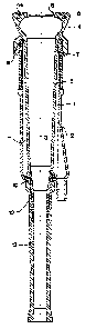
Fig 1 discloses a sectional view of a teatcup having a teatcup
liner according to an embodiment of the invention.
Fig 2 discloses a sectional view of the teatcup liner in
Fig 1, a
pretensioning member of the teatcup liner being disclosed
separately.
Fig 3 discloses a view from beneath of the pretensioning
member in Fig 2.
Fig 4 discloses a sectional view of a teatcup finer without
a
pretensioning member according to another embodiment
of
the invention.
Fig 5 discloses a sectional view of the teatcup liner in
Fig 4 with
a pretensioning member.
Fig 6 discloses a view from above of the teatcup liner in
Fig 5.
Fig 7 discloses a view similar to the one in Fig 6 of a teatcup
liner having a pretensioning member alternatively shaped.
Fig 8 discloses a sectional view of a teatcup liner without
a
pretensioning member according to another embodiment
of
the invention.
Fig 9 discloses a sectional view of the teatcup liner in
Fig 8 with
a pretensioning member.
Fig 10 discloses a sectional view of a teatcup liner in a
non-
pretensioned state according to a further embodiment
of
the invention.
Fig 11 discloses a sectional view of the teatcup liner in
Fig 10 in a
pretensioned state.
DETAILED DESCRIPTION OF DIFFERENT EMBODIMENTS
With reference to Figs 1-3, a teatcup is disclosed with a teatcup
liner 1 which is provided in a teatcup shell 2. The teatcup liner 1 is
essentially rotationally symmetrical with respect to a longitudinal
axis 3 and comprises an upper tubular head portion 4 and a tubular
CA 02270108 1999-04-27
WO 98119519 PCT/SE97/01845
7
shaft portion 5 extending downwardly from the head portion 4. The
head portion 4 comprises a first upper end 6 and a second lower
end 7. Beneath the upper end 6, the tubular head portion 4
comprises a lip 8 extending radially inwardly and defining an
essentially circular central opening. The tubular head portion 4
forms a passage between the first end 6 and the second end 7 to
the inner space of the teatcup finer for receiving a teat. The lower
end 7 comprises an annular recess 9 which is engaged by the upper
end portion of the teatcup shell 2. The lower part of the shaft portion
5 comprises a peripheral surrounding recess 10 which is engaged
by the lower end portion of the teatcup shell 2. The recesses 9 and
10 are shaped in such a manner that a closed space 11 is formed
between the teatcup liner and the teatcup shell 2, which space 11
forms a pulsating chamber of the teatcup. In its lower part, the
teatcup liner 1 connects to prolongation pieces 12 and 13, which
form a milk conduit which may be connected to a claw (not
disclosed). The teatcup liner 1 is manufactured in an elastic
material, for instance natural or synthetic rubber or any elastic
plastic material. In the upper end 6 of the head portion 4 there is a
pretensioning member 14 in the shape of a ring, the function of
which is to pretension or tighten the upper end 6 of the head portion
4 radially outwardly and in such a manner pull the lip 8 radially
outwardly and thus provide a pretension in the lip 8 which extends in
the peripheral direction of the lip. In such a manner, weakening of
the lip and any deformation, i.e. such as bending upwardly or
downwardly of especially radially inner parts thereof is
counteracted.
The pretensioning member 14 disclosed is now to be explained
more closely with reference to Fig 2 which discloses the teatcup
liner 1 removed from the teatcup shell 2 and the pretensioning
member 14 removed from the teatcup liner 1. It is to be noted that
when the teatcup liner 1 and the pretensioning member 14 are
separated from each other, as is disclosed in Fig 2, the diameter of
the pretensioning member 14 is in reality greater than the diameter
of a recess 7 5 in the upper end 6 of the head portion 4 for receiving
the pretensioning member 14. The pretensioning member 14
CA 02270108 1999-04-27
WO 98119519 PCT/SE97101845
according to this embodiment comprises a plurality of hooks 16
extending downwardly on the lower side of the ring and having hook
ends turned radiaily outwardly, see Figs 2 and 3. The circular recess
15 has a corresponding shape with depressions 17, which each is
arranged to receive and retain a hook 16. By this embodiment it is
ensured that the pretensioning member 14 may be fixed securely
and stable in the teatcup finer 1. The real radial tensioning force is
provided by the hooks 16 of the pretensioning member 14, which
extend downwardly from the ring and are focated at the same axial
level as the lip 8. Thanks to the hooks 16 being located in the
peripheral direction at a distance from each other and the
depressions, in the same way, being located at a distance from
each other in the peripheral direction, there is a connection between
a radially inner part and a radially outer part of the upper end 6 of
the head portion 4. In such a manner these inner and outer parts are
kept together and thus it is effectively prevented that a gap or a slit
may arise between the pretensioning member 14 and the teatcup
liner 1.
The teatcup liner disclosed in Figs 1-3 may be manufactured by first
being moulded, preferably by means of injection-moulding, and then
vulcanized. Thereafter the head portion 4 is expanded for instance
by means of an expansion tool (not disclosed). The expansion may
amount to about 1-20%, preferably 5-15%. Thereafter, the ring 14
provided with hooks 16 is introduced into the recess 15 in such a
manner that each hook 16 engages a respective depression 17.
Thereafter, the expansion force is removed. The teatcup liner 1 is
now complete and ready for delivery to a user. The user may now
without any difficulty mount the teatcup liner 1 in a teatcup shell 2
by simply inserting the teatcup liner 1 from above into the teatcup
shell 2 and pull the teatcup liner 1 until its recesses 9 and 10 are in
engagement with the teatcup shell 2.
Figs 4-6 disclose another embodiment of the teatcup finer 1
according to the invention. It is to be noted that elements or parts
having a corresponding function have been given the same
reference signs in the different embodiments. Also, according to this
CA 02270108 1999-04-27
WO 98119519 PCT/SE97101845
9
embodiment, the pretensioning member 14 comprises a ring which
is provided in an essentially circular recess 15 in the upper part 6 of
the head portion 4. The recess 15 is, which appears from Fig 4,
open upwardly as well as radially outwardly. The ring 15 is
connected to the radially inner limiting wall and the lower limiting
wall of the recess 15. The teatcup liner disclosed in Figs 4-6 may be
manufactured by first being moulded, as in the first embodiment and
at least partly vulcanized. Thereafter, the head portion is expanded,
for instance by means of an expansion tool (not disclosed), and the
teatcup liner 1 is provided in another mould which is shaped in such
a manner that a closed cavity is formed around the recess 15 having
a shape corresponding to the ring 14. Thereafter, a suitable
material, for instance a thermoplastic material, is injected into the
cavity so formed and this material is melted together or vulcanized
with the teatcup liner 1. Thereafter, the expansion force is removed.
However, the ring 14 in Figs 4-6 may also be a preproduced ring, for
instance of any metal or metal alloy, which is positioned in the
expanded recess 15 and vulcanized therein. Also other attachment
methods than vulcanizing may be used, for instance glueing. The
teatcup liner 1 manufactured in any of these ways may thereafter be
mounted in a teatcup shelf 2 in the same way as the teatcup liner 1
disclosed in Figs 1-3.
Fig 7 discloses a variant of this embodiment where the ring 14 is
divided into different portions 14A, 14B, 14C and 14D, which are
provided in such a manner that they form a ring configuration.
Between two adjacent portions, an elastic material extends radially
outwardly, which for instance may be the same material as in the
upper part 6 of the head portion 4. This embodiment is
advantageous due to the tact that it is elastic in a direction radially
outwardly, which means that an expansion tool which is introduced
into the head portion 4 during the provision of the pretensioning
member 14 in an easy way may be removed. It is to be noted that
also the pretensioning member 14 which is disclosed in Figs 1-3
may be shaped in this way, i.e. with a plurality of different ring
portions. It is also to be noted that the number of such portions may
be less or more than four as disclosed.
CA 02270108 1999-04-27
WO 98/19519 PCT/SE97/01845
Figs 8 and 9 disclose a further embodiment of the invention. Herein,
the teatcup liner 1 comprises a collar-like projection 18 which
extends upwardly from the upper end 6 of the head portion 4. The
5 projection 18 comprises at its outer end a circular thickened portion
19. The projection 18 and the thickened portion 19 are formed by
the same elastic material as the rest of the teatcup liner 1. Radially
outside the projection 18, a circular recess 15 is provided. Such a
teatcup liner 1 disclosed in Fig 8 may be moulded and vulcanized,
10 whereafter a pretensioning member 14 in the shape of a ring,
preferably of plastic or metal, is introduced into the recess 15.
Thereafter the collar-like projection 18 is folded downwardly over
the recess 15 in such a manner that the ring 14 is enclosed in a
cavity formed by the recess 15 and the collar-like projection 18.
Beneath the recess 15, the outer surface of the head portion 4
extends somewhat radially inwardly and the collar-like projection 18
has such a length that the thickened portion 19 will tighten the
collar-like projection 18 into this radially inwardly directed part of the
outer surface of the head portion 4. In this manner the pretensioning
member 14 is securely fixed in the teatcup liner 1 and this may now
be mounted in a teatcup shell 2 in the same way as the previously
disclosed embodiments. It is also to be noted that the pretensioning
member 14 disclosed in this latter embodiment may be divided into
different portions as is disclosed in Fig 7. Such a pretensioning
member 14 may comprise ring portions of for instance metal, which
are connected to each other by vulcanizing via intermediate ring
portions of any rubber material.
Figs 10 and 12 disclose a further embodiment which is similar to the
one in Figs 8 and 9 but where the pretensioning member 14
comprises an annular thickened portion or rib formed by the material
of the head portion 4. Thus, the ring device of the pretensioning
member 14 is an integrated part of the head portion 4. In order to
tighten the lip 8 the collar-like projection 18 is folded downwardly
over the annular thickened portion of material 14 in a corresponding
way as disclosed in connection with the description concerning Figs
8 and 9.
CA 02270108 1999-04-27
WO 98119519 PCT/SE97l01845
11
The present invention is not limited to the embodiments disclosed
above but may be varied and modified within the scope of the
following claims. Although the pretensioning member 14 and the
recess 15 have been disclosed having an essentially circular shape,
other shapes deviating from the circular shape are possible, for
instance oval. It is also to be noted that the teatcup shell 2 and the
teatcup liner 1 may have another than a circular cross-section
shape.