Note : Les descriptions sont présentées dans la langue officielle dans laquelle elles ont été soumises.
CA 02270278 1999-04-28
1
Title of the T_nvention
Filtering device
Background of the Invention
This invention relates to a filtering device and, more particularly, to a
filtering device suitable for use for precision filtering in a state submerged
in
liquid to be filtered. Liquid to be filtered includes water for general uses,
drinking water, river water, pool water and chemicals.
Known in the art of filtering device is one which employs a plurality of
filter tubes. In this filtering device, a plurality of filter tubes are
provided in
parallel in a container. Liquid to be filtered is introduced from an inlet
provided in one end portion of the container via a pump and filtered through
these filter tubes and filtered liquid, i.e., liquid which has passed through
the
filter tubes, is delivered out of a filtered liquid outlet provided in the
other end
portion of the container.
For the filter tubes used in the prior art filtering device, filter elements
for precision filtering which consists of a porous material or a filtering
cloth
having densely formed pores are used. In these filtering cloth having densely
formed pores of these filter elements, however, pores of these filter elements
are blocked by fine powdery materials suspending in the liquid to be filtered
in a relatively short period of time after starting of operation of the
filtering
device with the result that filtering efficiency is rapidly dropped. For this
reason, the filtering operation of the filtering device has to be stopped for
performing backwashing of the surface of the filter elements and resumed
after removing the materials which have blocked the pores of the filter
elements.
Backwashing has conventionally been made by supplying pressurized
backwash water from an outlet of filtered liquid of a container into a filter
tube to remove solids blocking pores of a filter element which constitutes the
CA 02270278 1999-04-28
2
filter tube.
In the conventional backwashing method, it frequently occurs that when
solids have been first dislodged from a part of pores which have been blocked
and the part of pores are thereby opened, the backwash water injects from the
part of pores which have been opened and the pressure of the backwash water
applied to the other pores which have not been opened yet thereby is reduced
with the result that the backwashing operation is finished while these pores
remain blocked with solids. Accordingly, even if backwashing is repeated
periodically, blocking of the filter element increases gradually until at last
it
becomes necessary to replace the entire filter element and this significantly
reduces the efficiency of the filtering device.
It is, therefore, a primary object of the invention to provide a filtering
device having an improved backwashing device capable of effectively
preventing blocking of a filter element.
Since a filter element of the conventional filtering device causes blocking
in a relatively short period of time, stopping of the filtering operation and
performing of backwashing must be made frequently with resulting decrease
in the filtering efficiency.
It is, therefore, another object of the invention to provide a filtering
device which can significantly reduce frequency of stopping of the filtering
operation and performing of backwashing in combination with the above
described improved backwashing device.
Summary of the Invention
For achieving the above described primary objects of the invention, there
is provided a filtering device comprising cylindrical screen, backwash tube
made of a tubular member provided in said cylindrical screen coaxially with
said cylindrical screen and rotatable about its axis, having an inlet for
introducing filtered liquid in one end portion thereof and an opening for
CA 02270278 1999-04-28
3
discharging filtered liquid and introducing backwash water in the other end
portion thereof and having a plurality of backwash water injection holes
formed in the axial direction at a predetermined interval, a liquid transfer
tube communicating with the opening for discharging the filtered liquid and
introducing the backwash water, a check valve provided on the side of said
opening for discharging the filtered liquid and introducing the backwash
water in the vicinity of the inlet for the filtered liquid for allowing
flowing of
the filtered liquid from the inlet for the filtered liquid into the backwash
tube
and prohibiting flowing of the backwash water from inside of the backwash
tube to the inlet for the filtered liquid, and backwash tube rotation means
for
rotating the backwash tube about its axis.
According to the invention, by injecting backwash water under pressure
from the backwash water injection holes formed at predetermined interval in
the axial direction while rotating the backwash tube about its axis in the
cylindrical screen, the backwash water is injected in a jet stream under a
concentrated large pressure and this jet stream of backwash water
sequentially collides with the entire inner periphery of the cylindrical
screen
as the backwash tube is rotated whereby blocking of the cylindrical screen is
removed uniformly over the entire inner periphery of the cylindrical screen.
In one aspect of the invention, said backwash tube rotation means is a
blade mounted on an inner surface of the backwash tube. According to this
aspect of the invention, when the backwash water under pressure is
introduced into the backwash tube, the flow of the backwash water pushes the
blade and the backwash tube thereby is rotated. Therefore, for rotating the
backwash tube, other drive unit including an electric motor and an electrical
driving circuit is unnecessary so that the filtering device can be constructed
in
a compact design at a minimum cost.
In another aspect of the invention, said backwash tube rotation means
consists of the backwash water injection holes of the backwash tube which are
CA 02270278 1999-04-28
4
formed at an angle to radial direction of the backwash tube in a horizontal
plane. According to this aspect of the invention, when the backwash water
under pressure is introduced into the backwash tube, the backwash water
stream which is injected from the injection holes which are offset from the
radial direction of the backwash tube collides with the inner wall surface of
the cylindrical screen in the form of an offset flow and the backwash tube
thereby is rotated in one direction. Therefore, as in the structure including
the blade mounted on the backwash tube, no other drive device is required for
rotating the backwash tube.
For achieving the above described second object of the invention, there is
provided a filtering device which further comprises a filter container in
which
one or more of said cylindrical screens are housed, said filter container
comprising an inlet for the liquid to be filtered, an outlet for the liquid to
be
filtered, a liquid transfer opening communicating with said liquid transfer
tube and a drain outlet, said inlet for the liquid to be filtered having a
larger
diameter than the liquid transfer opening, and a pump connected between
said inlet for the liquid to be filtered and said outlet for the liquid to be
filtered
to form a closed circuit between said inlet and outlet for the liquid to be
filtered, said pump acting to compulsorily introduce, from said inlet for the
liquid to be filtered, the liquid to be filtered of a larger amount than an
amount of the filtered liquid which can flow out of said liquid transfer
opening
thereby to create, in said filter container, a flow of the liquid to be
filtered
having a direction which is different from direction of a flow of the liquid
to be
filtered into the cylindrical screen.
According to the invention, there is created a flow of the liquid to be
filtered having a direction which is different from direction of a flow of the
liquid to be filtered into the cylindrical screen. Powdery solids causing
blocking of the screen suspending in the liquid to be filtered are washed away
from the surface of the cylindrical screen by the flow having the different
CA 02270278 2002-04-11
S
direction from the direction of the flow into the cylindrical screen and an
amount of
powdery solids v~rhich enter the slits of the cylindrical screen is reduced.
The speed of
blocking of the cylindrical screen thereby is reduced. Thus, together with the
effect of the
improvement in the backwashing by the rotary backwash tube, frequency of
stopping
driving of the filtering device for backwashing is reduced and the efficiency
of the filtering
operation is greatly improved.
In one aspect of the invention, a plurality of said filter containers are
provided in
parallel and the inlet for the liquid to be filtered, the outlet for the
liquid to be filtered, the
liquid transfer opening and the drain outlet of the respective filter
containers are connected
to one another by means of common connecting pipes to form a small size
module.
In still another aspect of the invention, the common connecting pipes of a
plurality
of said small size modules of filter containers are connected to one another
by means of
common connecting pipes for form a large size module.
In a broad aspect, the present invention relates to a filtering device
comprising: a
cylindrical screen; a backwash tube made of a tubular member provided in said
cylindrical
screen coaxially with said cylindrical screen and rotatably about its axis but
axially
immovably relative to said cylindrical screen, having an inlet for introducing
filtered liquid
in one end portion thereof and an opening for discharging filtered liquid and
introducing
backwash water in the other end portion thereof and having a plurality of
backwash water
injection holes formed in the axial direction at a predetermined interval,
said one end
portion being closed in its end by a plate and a pivot being provided in the
central portion
of an outside surface of the plate thereby enabling the backwash tube to
rotate on the pivot;
a liquid transfer tube communicating with the opening for discharging the
filtered liquid
and introducing the backwash water; a check valve provided inside of the
backwash tube
CA 02270278 2002-04-11
5(a)
on a side of said opening for discharging the filtered liquid and introducing
the backwash
water in the vicinity of the inlet for the filtered liquid for allowing
flowing of the filtered
liquid from the inlet for the filtered liquid into the backwash tube and
prohibiting flowing
of the backwash water from inside of the backwash tube to the inlet for the
filtered liquid;
and backwash tube rotation means for rotating the backwash tube about its
axis.
Preferred embodiments of the invention will be described below with reference
to
the accompanying drawings.
Sri f Description of the Drawints
In the accompanying drawings:
Fig. 1 is a perspective view showing an embodiment of the filtering device
made
according to the invention;
Fig. 2 is a vertical sectional view of the filtering device during the
filtering
operation;
Fig. 3 is a vertical sectional view of the filtering device during
backwashing;
Fig. 4 is an enlarged partial perspective view of the cylindrical screen;
Fig. 5 is a perspective view of the backwash tube;
._ _ _....__.,..~....,, m....~ ~:~~~ w n ;r ~;,. ~.
CA 02270278 1999-04-28
6
Fig. 7 is a view taken along lines B-B in Fig. 5;
Fig. 8 is a vertical sectional view showing another embodiment of the
filtering device during the filtering operation:
Fig. 9 is a sectional view showing the filtering device during
backwashing;
Fig. 10 is a view taken along lines C-C in Fig. 8;
Fig. 11 is a perspective view schematically showing another embodiment
of the invention;
Fig. 12 is a sectional view of the same embodiment;
Fig. 13 is a perspective view showing another embodiment of the
invention: and
Fig. 14 is a perspective view showing another embodiment of the
invention.
pescri~ntion of Preferred Embodiments
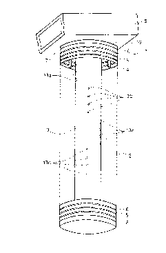
Figs. 1 to 7 illustrate an embodiment of the invention. A filtering device
1 includes a cylindrical screen 2 and a backwash tube 3 provided in the
cylindrical screen 2.
In the present embodiment, the cylindrical screen 2 has, as will be
apparent from Fig. 4, support rods 4 extending in the axial direction of the
screen 2 and arranged generally cylindrically with a predetermined interval
and having projecting portion 4a in radially outward end portion and a wedge
wire 5 wound spirally on the outside of the support rods 4 in substantially
crossing direction to the support rods 4. The wedge wire 5 is arranged with
its one side 5a facing outside and two other sides 5b and 5c forming a slit 6
which widens radially inwardly between adjacent wedge wire portions and
with an inward apex 5d of the wedge wire 5 being welded to the projecting
portion 4a of the support rods 4 at crossing points 7 of the wedge wire 5 and
the support rod 4. The upper portions of the wedge wire 5 and the support
CA 02270278 1999-04-28
rods 4 are welded to an annular flange 16 and the lower end of the screen 2 is
closed by a seal plate 8 (Fig. 1).
In Figs. 1 to 3, the upper and lower portions of the support rods 4 and the
wedge wire 5 of the cylindrical screen 2 are illustrated and the middle
portions thereof are shown by chain-and-dot lines.
As shown in Figs. 11 and 12, one or more of the cylindrical screens 2 may
be provided in ~ a filter container or containers with the seal plate 8
thereof
being in contact with the bottom plate of the filter container.
A liquid transfer tube 9 of a rectangular cross section is provided above
the cylindrical screen 2. In a bottom portion of the liquid transfer tube 9 is
formed a tubular opening 10 for discharging filtered liquid and introducing
backwash water coaxially with the cylindrical screen 2. The tubular member
forming the opening 10 is formed with a step in the central portion in
vertical
direction. A lower stepped portion l0a has a smaller outer diameter than an
upper stepped portion lOb.
The backwash tube 3 is made of a tubular member provided in the
cylindrical screen 2 coaxially with the cylindrical screen 2. An open upper
end portion of the backwash tube 3 is formed as a slide portion 3a which has
an inner diameter slightly larger than the outer diameter of the lower stepped
portion 10a of the tubular opening 10 of the liquid transfer tube 9 and is
fitted
in the outer periphery of the lower stepped portion 10a. The lower end of the
backwash tube 3 is closed by a bottom plate 3b in the form of a disk. A pivot
11 is provided in the central portion of the lower surface of the bottom plate
3b.
This pivot 11 is received in a pivot receiving recess 12 formed in the seal
plate
8 of the cylindrical screen 2 and the backwash tube 3 is thereby supported on
the cylindrical screen 2. By this construction, the backwash tube 3 can rotate
about its axis.
In the lower end portion of the backwash tube 3 is formed an opening 3c
for filtered liquid. The inlet 3c is made of a plurality of circular openings.
CA 02270278 1999-04-28
8
The upper open end portion of the backwash tube 3 constitutes an opening 3d
for discharging filtered liquid and introducing backwash water. This opening
3d communicates with the tubular opening 10 of the liquid transfer tube 9.
The backwash tube 3 has a plurality of backwash water injection holes
13 formed at a predetermined interval in the axial direction (vertical
direction). As will be apparent from Figs. 5 and 7, in the present
embodiment, groups of injection holes 13a, 13b, 13c and 13d each of which
consists of four vertically arranged injection holes are disposed at an
interval
of 90 degrees circumferentially. This arrangement ensures uniform injection
of backwash water and prevents occurrence of malfunction in the rotation of
the backwash tube 3 which may be caused by reaction due to one-sided
injection of the backwash water.
An optimum diameter of the injection holes 13 is 0.5mm - 0.8mm. If the
diameter exceeds 0.8mm, pressure of the injected backwash water is not
sufficient to effectively remove blocking. If the diameter is below 0.5mm,
there is likelihood that the injection holes will be blocked by fine dust.
As a preferred example, a backwash tube having a diameter of 20mm
may be provided in a cylindrical screen having a diameter of 70mm and
injection holes having a diameter of 0.7mm may be formed at an interval of
5mm in the backwash tube.
A check valve 14 is provided on the side of the opening 3d for discharging
the filtered liquid and introducing the backwash water in the vicinity of the
inlet 3c for the filtered liquid. The check valve 14 includes a valve main
body
14a in the form of a disk, an annular valve seat 14b on which the valve main
body 14a can be seated, a stem 14c extending upwardly in the axial direction
from the valve main body 14a, a valve holding member 14d (Fig. 6) consisting
of an annular member loosely receiving the stem 14c and four support rods
which secure the annular member fixedly to the inner wall of the backwash
tube 3, and a coil spring 14e which is fixed in one end to the valve main body
CA 02270278 1999-04-28
9
14a and in the other end to the valve holding member 14d. The coil spring
14e is adjusted in its spring force so that the coil spring 14e is in a
contracted
state when no pressure of the backwash water is applied thereto and expands
when it receives pressure of the backwash water to cause the valve main body
14a to be seated on the valve seat 14b. The check valve 14, therefore,
functions to allow introduction of the filtered liquid from the inlet 3c into
the
backwash tube 3 and prohibiting flowing out of the backwash water from
inside of the backwash tube 3 to the inlet 3c.
A blade 15 which constitutes the backwash tube rotation means for
rotating the backwash tube 3 about its axis during backwashing is mounted
fixedly on the upper inner wall surface of the backwash tube 3. The shape,
size and angle of attachment of the blade 15 are determined having regard to
the size of the backwash tube 3, magnitude of the backwash pressure and
ncessary rotation speed of the backwash tube 3 etc.
The operation of this filtering device will now be described.
During the filtering operation, the liquid to be filtered is supplied in a
filter container by actuating a pump. As shown in Fig. 2, the liquid to be
filtered flows into the cylindrical screen 2 through the slits 6 of the
cylindrical
screen 2 and the filtered liquid flows into the backwash tube 3 through the
inlet 3c. During this time, the check valve 14 is in an open state with the
coil
spring 14e contracted as shown in Fig. 2 so that the filtered liquid passes
through the check valve 14 and flows in the direction of the arrow and then
flows into the liquid transfer tube 9 through the opening 3d of the backwash
tube 3 and the tubular opening 10 of the liquid transfer tube 9 and is
delivered
out.
For the backwashing operation, the liquid to be filtered in the filter
container is discharged and then, as shown in Fig. 3, the backwash water
under pressure is introduced from the opening 10 of the liquid transfer tube 9
into the backwash tube 3 through the opening 3d. The valve main body 14a
CA 02270278 1999-04-28
of the check valve 14 is moved downwardly by the pressure of the backwash
water against the force of the coil spring 14e to be seated on the valve seat
14b
and thereby close the check valve 14. Accordingly, the backwash water under
pressure in the backwash tube 3 is injected in the form of a jet stream from
each of the backwash water injection holes 13 and this jet stream collides
against the cylindrical screen 2. In the meanwhile, the backwash water flow
strikes against the blade 15 and thereby pushes the blade 15 so that the
backwash tube 3 is rotated about its axis. The strong jet streams of the
backwash water sequentially collide against the entire inner periphery of the
cylindrical screen 2 as the backwash tube 3 is rotated whereby blocking of the
slits of the cylindrical screen 2 over the entire circumference can be
uniformly
removed.
Figs. 8 to 10 show another embodiment of the invention. In this
embodiment, the same component parts as those of the embodiment of Figs. 1
to 7 are designated by the same reference characters and description thereof
will be omitted.
This embodiment is different from the embodiment of Figs. 1 to 7 in that
the backwash tube rotation means is not the blade 15 as in the embodiment of
Figs. 1 to 7 but, as shown in Fig. 10, is made of backwash water injection
holes
30 (30a, 30b, 30c and 30d) of the backwash tube 3 which are formed at a
predetermined angle with respect to the radial direction of the backwash tube
3 in a horizontal plane. In the present embodiment, when the backwash
water under pressure is introduced into the backwash water, the backwash
water is injected from the offset injection holes 30 in the form an offset jet
stream and collides against the inner wall surface of the cylindrical screen
2.
As a result, the backwash tube 3 is rotated in the direction of the arrow D
(Fig.
10). The other structure and operation of this embodiment are the same as
those of the embodiment of Figs. 1 to 7.
Figs. 11 and 12 show another embodiment of the invention.
CA 02270278 1999-04-28
11
In this embodiment, one or more (five in the illustrated example)
cylindrical screens 2 are provided in parallel in a box-like filter container
40.
Each of these cylindrical screens is the one shown in Figs. 1 to 7 or Figs. 8
to
10. The openings for discharging the filtered liquid and introducing the
backwash water of the backwash tubes 3 in the respective cylindrical screens
2 communicate with a common liquid transfer tube 41.
The filter'' container 40 has an inlet 42 for the liquid to be filtered, an
outlet 43 for the liquid to be filtered, a liquid transfer opening 44
communicating with the liquid transfer tube 41 for the backwash tubes 3 and
a drain outlet 45 which can be opened and closed as desired. The inlet 42 for
the liquid to be filtered has a larger diameter than the liquid transfer
opening
44. A pump 46 is connected between the inlet 42 for the liquid to be filtered
and the outlet 43 for the liquid to be filtered to form a closed circuit
between
the inlet and outlet for the liquid to be filtered for circulation of the
liquid to be
filtered. By actuating the pump 46, the liquid to be filtered of a larger
amount than an amount of the filtered liquid which can flow out of the liquid
transfer opening 44 is compulsorily introduced from the inlet 42 and this
creates, in the filter container 40, a flow (i.e., the circulating flow shown
by
arrow F in Fig. 11) of the liquid to be filtered having a direction which is
different from direction of a flow of the liquid to be filtered into the
cylindrical
screen 2 through the slits 6.
In this embodiment, during the filtering operation, the drain outlet 45 is
closed and the liquid to be filtered is supplied to the filter container 40.
The
liquid to be filtered flows into the cylindrical screen 2 and the filtered
liquid is
taken out of the liquid transfer opening 44 through the liquid transfer tube
41.
Superfluous liquid to be filtered constitutes a flow having a direction which
is
different from direction of the flow into the cylindrical screen 2 and
circulates
in the filter container 40 thereby washing away powdery solids which cause
blocking of the cylindrical screen 2 from the surface of the cylindrical
screen 2
CA 02270278 1999-04-28
12
and thereby reducing the amount of blocking.
During the backwashing operation, the inlet 42 and the outlet 43 of the
filter container 40 are closed and, after finishing filtering of the liquid to
be
filtered in the filter container 40, the drain outlet 45 is opened. Then, the
backwash water under pressure is introduced from the liquid transfer opening
44 to perform backwashing in the manner described above. The soiled water
after backwashing is drained from the drain outlet 45.
Fig. 13 shows another embodiment of the invention in which a plurality
(six in the illustrated example) of the filter containers 40 of Figs. 11 and
12
disposed in parallel. The inlets 42 of the respective filter containers 40 are
connected together by means of a common connecting pipe 52. The outlets 43
of the respective filter containers 40 are connected together by means of a
common connecting pipe 53. The liquid transfer openings 44 of the
respective filter containers 40 are connected together by means of a common
connecting pipe 54. The drain outlets 45 of the respective filter containers
40
are connected together by means of a common connecting pipe 55. By this
arrangement, the filter containers 40 are combined together to form a small
size module 50.
Fig. 14 shows another embodiment of the invention in which a plurality
(three in the illustrated example) of the small size modules 50 are disposed
in
parallel. The common connection pipes 52, 53, 54 and 55 are respectively
connected together by means of further common pipes 62, 63, 64 and 65
respectively to form a large size module 60.
In the above described embodiments, the cylindrical screens 2 are made
as wedge wire screens. Alternatively, the cylindrical screens may be made of
other filters elements such as wire-mesh and filter cloth.
As will be apparent from the foregoing description, the filtering device of
the present invention can be used as a single cylindrical screen or can be
used
in the form in which a plurality of cylindrical screens are provided in a
single
CA 02270278 1999-04-28
13
filter container or in the form in which such filter containers are combined
to
form a small size module or in the form in which such small size modules are
combined to form a large size module.
As the backwash tube rotation means for rotating the backwash tube
about its axis, the blade mounted on the inner wall of the backwash tube or
the offset injection holes are preferable but the backwash tube rotation means
is not limited to them but the backwash tube may be rotated by an external
rotation drive device such as an electric motor or a magnetic stirrer.
In the above described embodiments, the groups of the backwash water
injection holes formed in the backwash tube are provided at an interval of 90
degrees circumferentially. Alternatively, the circumferential interval
between each group of injection holes may be other angle such as 60 degrees
or 180 degrees. In the above described embodiments, only one injection hole
is formed circumferentially. Alternatively, two or more injection holes may be
formed circumferentially depending upon condition of injection of the
backwash water. In short, the number and location of the injection holes
may be so determined that blocking of the cylindrical screen will be
completely removed through backwashing by rotation of the backwash tube
and malfunction in the rotation of the backwash tube caused by offsetting of
the axis of the backwash tube due to reaction by the injection of the backwash
water will be prevented.