Note : Les descriptions sont présentées dans la langue officielle dans laquelle elles ont été soumises.
CA 02270441 1999-04-30
Safety device to prevent the unlawful appropriation of shop goods
The present invention relates to a safety device to prevent the unlawful
appropriation of shop
goods, especially to protect video, audio and other data carrying equipment,
which contains a
case with an internal space suitable for accommodating the goods, a filling
opening for putting the
goods in the internal space of the case, a covering element which covers the
filling opening at
least partly, a partial fixing unit for locking the covering element, and a
signalling partial unit is
connected to the inside of the bordering wall of the case.
Several solutions have become known to prevent the unlawful appropriation of
the goods
introduced and offered for sale in the different shops. Among these there are
the safety systems in
the case of which the products intended to be protected are equipped with
passive aerials, so-
called goods protecting labels, made of metal foil, fixed on a paper or
plastic carrier, and in the
shop, practically near the exits, there are receiver-transmitter partial units
radiating signals at a
determined frequency. When these are in operation, if an active goods
protecting label gets into
the protected area, the safety system alarms with the help of sound and light
effects, and prevents
the goods from being taken out of the shop unlawfully.
Such devices are described in patent specifications No. EP 704.591 and FR
2.727.549.
However, in the case of products which are supplied for the shops in a cases,
boxes or in some
other packaging, there is the possibility of that the person intending to
misappropriate the product
tries the take it out of the selling place by leaving the packaging behind.
Such products are,
among other, tapes, CD-s or computer discs suitable for recording and storing
audio and video
signals.
Safety devices have also been developed for the protection of video, audio and
other data
carrying devices. The essence of these is that the goods, with their original
packaging, are put in a
case that can be locked, practically made of transparent material, also
accommodating the
packaging. The partial unit which activates the safety equipment is placed in
the internal space of
the safety device, next to the goods intended to be protected.
CA 02270441 1999-04-30
~-
Such safety devices equipped with a storing space are described among others
in patent
specifications No. WO 92/08026, US 5.147.034 and WO 97/166 15, while
information relating to
signalling units which activate the different safety equipment is contained
among others in patent
specification No. WO/9624119.
However, the defect of the known safety devices is that the separate
signalling partial unit put
in the internal space which accommodates the foods may be easily damaged in
the course of
putting the goods in the internal space and taking them out of there, and it
may result in the failure
of the alarm.
In the case of the signalling partial units connected to the protective case
it is a problem that,
especially in the case of the cases for the protection of the CD-s, the goods
intended to be
protected shades the signalling partial unit with radio-frequency, and so the
partial unit is not able
to emit signals of appropnate intensity and to turn on the safety device.
It must also be regarded as a disadvantage, that the manufacturing cost of the
known signalling
partial units put in the internal space of the protective case is relatively
high, and it is still
susceptible to breaking down.
It is also unfavourable that in the interest of reaching appropriate
sensitivity the known
signalling partial units are relatively spacious, and due to this in many
cases they often cover
information important for the customer on the packaging of the goods to be
protected, and so
their application may be a disturbing, purchase impeding factor.
Our aim with the packaging according to the sample is to overcome the defects
of the known
safety devices and to create a version which makes it possible to create a
simple construction
which is resistant to physical exposures and is equipped with a signalling
partial unit which can be
appropriately fixed in the internal space of the case and which is able to
give a signal the intensity
of which suits the safety equipment under all circumstance, independently from
the material or
size of the goods to be protected.
The safety device according to the sample was resulted by the recognition that
if the signalling
partial unit is constructed differently from the usual, and it is put and
fixed in the internal space of
the case in a specific way diffl"erent from the known ways, then the task can
be solved.
CA 02270441 1999-04-30
-3-
Suiting the set aim the safety device according to the utility model to
prevent the unlawful
appropriation of shop goods, especially to protect video, audio and other data
carrying devices,
which contains a case with an internal space suitable for accommodating the
goods, a filling
opening for putting the goods in the internal space of the case, a covering
element which covers
the filling opening at least partly, a partial fixing unit for locking the
covering element, and a
signalling partial unit is placed in the internal space of the case, is
constructed in a way that the
signal providing partial unit has a single loop-shaped wire aerial returning
to itself, and it has an
electric partial unit inserted between the one end and the other end of the
wire aerial, the internal
side of the bordecing wall of the case and/or the internal side of the
covering element is provided
with intermediate sections, and the signal providing partial unit is fixed
safely by the intermediate
sections in the internal space of the case.
Another criterion of the safety device according to the utility model can be
that at least one
section of the wire aerial is placed near or practically adjusted to the
connection line of the side
elements forming the bordering wall.
In the case of a planned construction of the safety device the electnc partial
unit contains a
circuit disc and a capacitive element fixed to the circuit disc and/or an
inductive element.
In the case of another construction of the sample the intermediate sections
are pins made of the
material of the case, forming an organic unit with it, stretching towards the
internal space of the
case, and their free ends, in their fixed position, are bent onto the wire
aerial of the signal
providing partial unit.
In the case of a further version of the safety device the intermediate
sections are formed by
bedding spots made of afterhardening material, placed on the internal side of
the bordering wall of
the case, and the wire aerial of the signal providing partial unit and/or the
circuit disc of the
electric partial unit are pressed into the bedding spots while they are still
soft.
It is favourable from the aspect of the creation of the sample, if the
proportion of the index-
number of the length of the wire aerial of the signal providing partial unit
expressed in mm and
the index-number of the area surrounded by the wire aerial expressed in mm2 is
at least 1:1.
CA 02270441 1999-04-30
-4-
The safety device according to the utility model has several advantageous
characteristic
features. Among these the most important is that its application excludes the
damaging of the
signal providing partial unit in the course of putting the goods to be
protected in the internal space
of the case or taking them out of there, and due to this it is able to start
the alarm equipment with
significantly higher safety.
Due to the specific construction and position of the wire aerial of the signal
providing partial
unit the sensitivity of the safety device improves and the signal emitted by
it becomes more
intensive which has a favourable influence on the desired operation of the
safety equipment.
It must also be regarded as favourable that due to the position of the wire
aerial the goods to be
protected do not shade the electric elements forwarding the signals, not even
in the case of CD-s,
and so the signalling ability and reliability of the safety device is
increased even more.
It must also be regarded as an advantage that the running and of the wire
aerial and its fixing to
the case also excludes the possibility of the signal providing partial unit
covering some information
important for the customers on the packaging of the goods intended to be
protected and thus
causing some inconvenience for the customers or the sales-persons during or
after the purchase.
It must also be mentioned as an advantage that the manufacturing of the signal
providing
partial unit and its placement in the case does not need special manufacturing
devices, special
manufacturing technology or special expensive materials, so even in the case
of small series it can
be easily produced.
The sample is described in more detail in connection with the construction
example. In the
drawing
Figure No. 1. is the view of a possible construction of the safety device
according to the
sample,
Figure No. 2. is the part showing the connection between the signal providing
partial unit and
the case, partly in shown in section
CA 02270441 1999-04-30
-5-
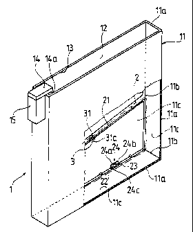
In figure No. 1. a possible construction of the safety device according to the
sample can be
seen. The I case containing the 12 internal space surrounded by the 11
bordering wall composed
from the 11 a side elements can be seen in the I 1 bordering wall of which the
13 filling opening is
constructed. The 13 filling opening, in the case of the present construction,
is partly closed by the
14 covering element equipped with the 15 fixing partial unit, where the 15
fixing partial unit
ensures the closed position of the 14 covering element, and a specific
auxiliary device is needed to
open it.
Of course the 14 covering element can be moved so that during the period when
the goods to
be protected are put in, it leaves the 13 filling opening free and then closes
it after the goods to be
protected have been put in.
The 2 signal providing partial unit is situated inside the 12 internal space
of the I case, it
contains the 21 wire aerial and the 24 electric partial unit connected between
the 22 one end and
the 23 other end of the 21 wire aerial. In the case of the present
construction the 24 electric partial
unit is assembled from the 24a circuit disc and the 24b capacitive element
placed
on the 24a circuit disc. Another version is also possible in the case of which
a 24c inductive
element is also placed on the 24a circuit disc, but it is not necessary as the
21 wire aerial itself can
be regarded as an inductive member. From the above it can be seen that the 2
signal providing
partial unit is in fact an oscillating circuit which, in the case of the input
of a determined energy
package, with a decay of a given period, emits a signal in proportion with the
amount of energy
received.
Figure No. 1. also demonstrates that the 21 wire aerial of the 2 signal
providing partial unit is a
single loop-like plane form returning to itself, and practically at least one
part of it is fixed to the
I lc internal side in the 12 internal space of the 1 case, practically along
the 1 lb connection line of
the I la side elements forming the 11 bordering wall of the I case. It must be
pointed out here that
in the interest of improving the radiation characteristics of the 21 wire
aerial made of metal, the
external surface of the 21 wire aerial can be provided with a coating which
can be silver-coating
practically.
CA 02270441 1999-04-30
-6-
The I case and the 21 wire aerial of the 2 signal providing partial unit are
connected by the 3
intermediate sections which, in the case of the present construction, are 31
pins made of the
material of the I case and stretching in the 12 internal space of the I case.
The 31 a free ends of
the 31 pins are constructed and placed here so that the 21 wire aerial of the
2 signal providing
partial unit can be stringed onto them, and after bumping the 21 wire aerial
to the lla side
elements of the I case, the 31 a free ends of the 31 pins stretch over the 21
wire aerial. Due to this
basic situation the 3 l a free ends of the 31 pins, in their fixed position,
can be bent back onto the
21 wire aerial. It must be pointed out here that in the interest of achieving
the favourable signal
transmitting characteristics the position of the 31 pins must be chosen so
that the proportion
between the index-number of the "h" length of the 21 wire aerial measured in
mm and the index-
number of the values of the "A" area surrounded by the 21 wire aerial measured
in mm2 must be
at least 1:1.
When making the safety device according to the sample, the 1 case is produced
in itself, in
the known way, from water-clean transparent material, practically by injection
moulding, and
from its 11 a side elements forming the 11 bordering wall 31 pins stretch out
towards the 12
internal space of the I case on the desired places. After this a 21 wire
aerial is made the running of
which is determined by the 31 pins of the 11 a side elements forming the 1 l
bordering walls of the
1 case and the 11 b connections lines of the 11 a side elements, and the 22
one end and the 23
other end of which are connected to the 24 electric partial unit also in a
traditional way, for
example by soldering, and thus the 2 signal providing partial unit of the
desired size and shape is
produced.
After the 2 signal providing unit has been made, the 21 wire aerial is
stringed onto the 31 pins,
and it is put in contact with 11 bordering wall of the I case so that each of
the 31 pins stretch over
the 21 wire aerial. Finally the 31 a free ends of the 31 pins are bent onto
the 21 wire aerial with a
hot tool, and so it is fixed in the 12 internal space of the I case in the
desired position.
Figure No. 2. shows a part of a safety device version where the 2 signal
providing unit is fixed
CA 02270441 1999-04-30
-7-
to the 14a internal side of the 14 covering elements which closes the 13
filling opening of the 1
case completely in this case, and the 3 intermediate sections are the 32
bedding spots made of the
afterhardening material, for example glue material, placed on the 14a internal
side of the 14
covering element. In this case, in order to create safe fixing between the 21
wire aerial and the I
case, first 32 bedding spots are dropped on the desired paces, then the 21
wire aerial is pressed
into these 32 bedding spots while they are still in a liquid state, and we
wait until the 32 bedding
spots become hard. Then the 21 wire aerial of the 2 signal providing partial
unit is connected to
the 1 case by the hardened material in the 32 bedding spots.
It is obvious now that the 2 signal providing partial unit can be fitted not
only on the 11
bordering wall of the I case, but also on the 14a internal side of the 14
covenng element, and
even another version is possible which is the combination of the above two.
The safety device according to the sample can be used well to prevent the
unlawful
appropriation of goods in shops where there is electronic, radio frequency
alarm operated safety
equipment.
It will be understood that, although various features of the invention have
been described
with respect to one or another of the embodiments of the invention, the
various features and
embodiments of the invention may be combined or used in conjunction with other
features and
embodiments of the invention as described and illustrated herein.
Although this disclosure has described and illustrated certain preferred
embodiments of the
invention, it is to be understood that the invention is not restricted to
these particular
embodiments. Rather, the invention includes all embodiments which are
functional, electrical or
mechanical equivalents of the specific embodiments and features that have been
described and
illustrated herein.