Sélection de la langue

Search

Sommaire du brevet 2270451 

Énoncé de désistement de responsabilité concernant l'information provenant de tiers

Une partie des informations de ce site Web a été fournie par des sources externes. Le gouvernement du Canada n'assume aucune responsabilité concernant la précision, l'actualité ou la fiabilité des informations fournies par les sources externes. Les utilisateurs qui désirent employer cette information devraient consulter directement la source des informations. Le contenu fourni par les sources externes n'est pas assujetti aux exigences sur les langues officielles, la protection des renseignements personnels et l'accessibilité.

Disponibilité de l'Abrégé et des Revendications

L'apparition de différences dans le texte et l'image des Revendications et de l'Abrégé dépend du moment auquel le document est publié. Les textes des Revendications et de l'Abrégé sont affichés :

  • lorsque la demande peut être examinée par le public;
  • lorsque le brevet est émis (délivrance).
(12) Demande de brevet: (11) CA 2270451
(54) Titre français: SYSTEME OPTIQUE D'APPOINT POUR APPAREIL PHOTO
(54) Titre anglais: SUPPLEMENTARY OPTICAL SYSTEM FOR A CAMERA
Statut: Réputée abandonnée et au-delà du délai pour le rétablissement - en attente de la réponse à l’avis de communication rejetée
Données bibliographiques
(51) Classification internationale des brevets (CIB):
  • G02B 15/10 (2006.01)
  • G02B 27/00 (2006.01)
(72) Inventeurs :
  • WEIGEL, WOLFGANG (Allemagne)
  • ROESSEL, WOLFGANG (Etats-Unis d'Amérique)
(73) Titulaires :
  • CINE PHOTO TECH INC.
(71) Demandeurs :
  • CINE PHOTO TECH INC. (Etats-Unis d'Amérique)
(74) Agent: SMART & BIGGAR LP
(74) Co-agent:
(45) Délivré:
(22) Date de dépôt: 1999-04-30
(41) Mise à la disponibilité du public: 1999-12-17
Licence disponible: S.O.
Cédé au domaine public: S.O.
(25) Langue des documents déposés: Anglais

Traité de coopération en matière de brevets (PCT): Non

(30) Données de priorité de la demande:
Numéro de la demande Pays / territoire Date
198 27 018.6 (Allemagne) 1998-06-17

Abrégés

Abrégé anglais


A supplementary optical system for a camera which is inserted
between a photographic lens and a camera housing and which comprises a relay
system for projecting an image of the photographic lens onto a film or a video
recording material, wherein the relay system produces more than one image and
a
zoom lens is disposed on the camera body. The supplementary optical system
permits focusing and other camera controls to be operated near the camera
housing. Additionally, this invention can be converted for performing
different
tasks in a simple manner due to the employment of path bending units.

Revendications

Note : Les revendications sont présentées dans la langue officielle dans laquelle elles ont été soumises.


THE EMBODIMENTS OF THE INVENTION IN WHICH AN EXCLUSIVE
PROPERTY OR PRIVILEGE IS CLAIMED ARE DEFINED AS FOLLOWS.
1. A supplementary optical system for a camera which is inserted
between a photographic lens and a camera housing having an optical path
and a relay system for projecting an image of said photographic lens onto
a film, wherein said relay system includes means for producing more than
one image, and wherein a lens disposed on said camera housing is a zoom
lens.
2. The supplementary optical system according to Claim 1, wherein a
path-bending unit is arranged between said photographic lens and said
relay system.
3. The supplementary optical system according to Claim 2, wherein
said path-bending unit comprises two elements, one of said two elements
bending said optical path through 90 degrees.
4. The supplementary optical system according to Claim 3, wherein
one of said two elements is tiltable together with said photographic lens
such that a respective swing angle of said photographic lens is twice the
magnitude of a swing angle of said tiltable element.
5. The supplementary optical system according to Claim 4, wherein
said tiltable element is a front-surface minor.
6. The supplementary optical system according to Claim 5, wherein
said relay system comprises first, second, and third lenses, and a zoom
7

lens, a prism being disposed between said first and second lenses for
image rotation; and
wherein said second and third lenses provide a similar or
equivalent design and are disposed in symmetry relative to the center-plane
between them.
7. The supplementary optical system according to Claim 3, wherein
one of said two elements is a front-surface mirror and the other of said two
elements is a path-bending element having image reversion.
8. The supplementary optical system according to Claim 7, wherein
one of said two elements is tiltable together with said photographic lens
such that a respective swing angle of said photographic lens is twice the
magnitude of a swing angle of the tiltable element.
9. The supplementary optical system according to Claim 8, wherein
said tiltable element is a front-surface mirror.
10. The supplementary optical system according to Claim 9, wherein
said relay system comprises first, second, and third lenses, and a zoom
lens, a prism being disposed between said first and second lenses for
image rotation; and
wherein the second and third lenses provide a similar or equivalent
design and are disposed in symmetry relative to a center-plane between
them.
8

11. The supplementary optical system according to Claim 7, wherein
said path-bending element having image reversion is a roof-type system.
12. The supplementary optical system according to Claim 11, wherein
one of said two elements is tiltable together with said photographic lens
such that a respective swing angle of said photographic lens is twice the
magnitude of a swing angle of the tiltable element.
13. The supplementary optical system according to Claim 12, wherein
said tiltable element is a front-surface mirror.
14. The supplementary optical system according to Claim 9, wherein
said relay system comprises first, second, and third lenses, and a zoom
lens, wherein a prism is disposed for image rotation between said first and
second lenses; and
wherein the second and third lenses provide a similar or equivalent
design and are disposed in symmetry relative to the center-plane between
them.
15. The supplementary optical system according to Claim 1, wherein
said relay system comprises first, second, and third lenses, and a zoom
lens.
16. The supplementary optical system according to Claim 15 wherein
a prism is disposed between said first and second lenses for image
rotation.
9

17. The supplementary optical system according to Claim 15 wherein
the second and third lenses provide a similar or equivalent design and are
disposed in symmetry relative to a center-plane between them.
18. The supplementary optical system according to Claim 16 wherein
the second and third lenses present a similar or equivalent design and are
disposed in symmetry relative to the center-plane between them.
19. The supplementary optical system according to Claim 17 wherein
the zoom lens is a varifocal lens.
20. The supplementary optical system according to Claim 18 wherein
the zoom lens is a varifocal lens.

Description

Note : Les descriptions sont présentées dans la langue officielle dans laquelle elles ont été soumises.

CA 02270451 1999-04-30
SUPPLEMENTARY OPTICAL SYSTEM FOR A CAMERA
BACKGROUND OF THE INVENTION
1. Technical Field
The present invention relates to a supplementary optical system for
a camera which is inserted between a photographic lens and a camera housing
and
which comprises a relay system for projecting an image of the photographic
lens
onto film or a video recording medium.
2. Background Information
A supplementary optical system is known from European Patent
A-0 690 327. Such systems may be used with still cameras, film cameras, or
video cameras. Additional supplementary optical systems of the general type
are
known from U.S. Patent Nos. 5,469,236 and 4,867,549. Explicit reference is
made to these documents for an explanation of all the features which are not
described in detail in this application.
All of the known supplementary optical systems have the feature in
common that the normal camera lens, which is directly located on the camera
housing, is attached to the supplementary system so that it presents a more or
less
wide spacing from the camera housing, depending on the design of the
supplementary system. Especially when the camera lens is a variable power or
zoom lens, this feature renders the operation more difficult for the operator
1
NYB 1035908.2

CA 02270451 1999-04-30
because the controls for focal length adjustment and for operation of other
camera
elements are spaced at a comparatively wide distance from the camera housing.
It is moreover inexpedient in the known systems in that they
cannot be adapted to handle different tasks in a simple manner. For instance,
it is
not possible to simply use each of the known systems both as a straight system
and as a bent system after simple conversion.
The subject invention is now based on the problem to improve a
supplementary optical system for a camera in such a way that handling will be
facilitated and that the system can be converted for different tasks in a
simple
manner.
One inventive solution to this problem is defined in Patent Claim
1. Improvements of the invention are the subj ect matters of Claims 2 et seq.
In
accordance with the subj ect invention the relay system may be structured so
that it
produces more than one image and so that the lens disposed directly on the
camera body is a zoom lens.
It is therefore not only possible to perform focusing and rotation of
the image close to the camera, but moreover the image section can be selected.
In
particular, the zoom lens may be a varifocal lens, i.e., a lens in which
focusing is
not varied when the focal length is varied.
Due to this configuration it is furthermore possible to convert the
supplementary optical system of the present invention in a comparatively
simple
2
NYB 1035908.2

CA 02270451 1999-04-30
manner. It is possible in particular to select the object-to-lens distance
between
the image of the photographic lens and the first image to be so wide that
further
systems such as path-bending units may be accommodated in this zone.
It is particularly preferred that the path-bending unit be disposed
between the photographic lens and the relay system because in such a case the
optical system, which is arranged in the taking path ahead of the path-bending
unit, is of a comparatively small and hence light-weight design.
In another configuration, the path-bending unit comprises two
elements of which at least one bends the light path through 90 degrees. With
this
design in particular an offset of the optical axis can be achieved which
enables the
operator to manage complicated taking situations, such as those involved in
macro
photography, by means of the inventive supplementary system of the present
invention.
One of these elements may be a front-surface mirror whereas the
other element may be a path-bending element with image reversion so that a non-
reversed image is obtained with an intermediate image.
The aforementioned design permits not only an offset of the optical
axis but also a tilt of the offset optical axis. To this end an element can be
rotated
together with the photographic lens in such a way that the respective swing
angle
of the photographic lens amounts to twice the magnitude of the swing angle of
the
tilting element. The tilting element may be the front-surface mirror in
particular.
3
NYB 1035908.2

CA 02270451 1999-04-30
In a preferred embodiment of the present invention the relay
system includes three lenses and the zoom lens, with a prism being disposed
for
image rotation between the first and the second lenses. The two lenses, which
are
arranged between the image rotation prism and the zoom lens, are preferably of
a
similar or equivalent design and preferably are disposed in symmetry relative
to
the center plane therebetween.
The invention will be described in the following by exemplary
embodiments, with reference to the drawings, but without implying any
restriction
of the general inventive idea. With respect to the disclosure of all inventive
aspects which are not explained in more detail in the text, reference is
explicitly
made to the drawing as well.
BRIEF DESCRIPTION OF THE DRAWINGS
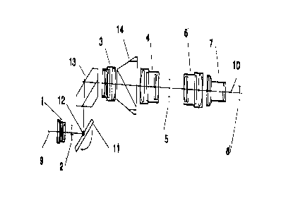
Fig. 1 illustrates the fundamental configuration of one
embodiment;
Fig. 2 shows a modification of the embodiment illustrated in Fig.
1, showing the offset of the optical axis of the photographic lens and the
relay
system; and
Fig. 3 is a view of a roof prism as used in the invention.
4
NYB 1035908.2

CA 02270451 1999-04-30
DETAILED DESCRIPTION
Fig. 1 shows a first embodiment of the invention in which the relay
system is configured so that it produces more than just one intermediate
image.
To this end optical relay systems 3, 4, and 6 as well as an optical
zoom unit 7 are arranged between an optical taking system 1 and an image plane
8 in which a film or a video recording material may be provided. The optical
taking system 1 produces an image in a first intermediate plane 2. This image
is
projected in the second intermediate image plane 5 by the first relay system
which
consists of the optical relay systems 3 and 4 in tandem. The image produced in
this image plane is projected into the film or video recording plane 8 by the
second relay system which consists of the optical relay system 6 with an
invariable focal length and zoom lens 7. The zoom lens permits a setting of
the
image section without the operator being required to operate a taking lens
which
is spaced by a wide distance due to the relay system.
Fig. 2 shows a second embodiment in which the same elements as
those shown in Fig. 1 are provided with the same reference numerals so that a
repeated description will be dispensed with here.
In these embodiments elements are provided between the first
intermediate image plane 2 and the first relay system, which consists of the
optical relay units 3 and 4, which elements offset an optical axis 9 of the
optical
taking system 1 relative to an optical axis 10 shared in common by the optical
systems 3, 4, 6 and 7. These elements include a front-surface mirror 11 which
5
NYB 1035908.2

CA 02270451 1999-04-30
may be tilted about an axis 12 normal on the optical axis 9, and a roof prism
13
with image reversion.
Moreover, a prism 14 is disposed between the optical relay system
3 and 4 for image rotation. The prism 14 is shown in more detail in Fig. 3.
The optical taking system 1 may be tilted together with the front-
surface mirror 11 in such a way that the respective swing angle of the optical
taking system 1 is twice as wide as the swing angle of the front-surface
mirror 11
about the axis 12.
Fig. 3 shows an embodiment of the roof prism 13.
6
NYB 1035908.2

Dessin représentatif
Une figure unique qui représente un dessin illustrant l'invention.
États administratifs

2024-08-01 : Dans le cadre de la transition vers les Brevets de nouvelle génération (BNG), la base de données sur les brevets canadiens (BDBC) contient désormais un Historique d'événement plus détaillé, qui reproduit le Journal des événements de notre nouvelle solution interne.

Veuillez noter que les événements débutant par « Inactive : » se réfèrent à des événements qui ne sont plus utilisés dans notre nouvelle solution interne.

Pour une meilleure compréhension de l'état de la demande ou brevet qui figure sur cette page, la rubrique Mise en garde , et les descriptions de Brevet , Historique d'événement , Taxes périodiques et Historique des paiements devraient être consultées.

Historique d'événement

Description Date
Inactive : CIB de MCD 2006-03-12
Demande non rétablie avant l'échéance 2005-05-02
Le délai pour l'annulation est expiré 2005-05-02
Inactive : Abandon.-RE+surtaxe impayées-Corr envoyée 2004-04-30
Réputée abandonnée - omission de répondre à un avis sur les taxes pour le maintien en état 2004-04-30
Inactive : Grandeur de l'entité changée 2002-04-19
Demande publiée (accessible au public) 1999-12-17
Inactive : Page couverture publiée 1999-12-16
Inactive : Certificat de dépôt - Sans RE (Anglais) 1999-10-06
Lettre envoyée 1999-09-17
Demande de priorité reçue 1999-08-30
Inactive : Transfert individuel 1999-08-30
Inactive : CIB attribuée 1999-06-15
Inactive : CIB en 1re position 1999-06-15
Inactive : Certificat de dépôt - Sans RE (Anglais) 1999-06-03
Demande reçue - nationale ordinaire 1999-05-31

Historique d'abandonnement

Date d'abandonnement Raison Date de rétablissement
2004-04-30

Taxes périodiques

Le dernier paiement a été reçu le 2003-04-08

Avis : Si le paiement en totalité n'a pas été reçu au plus tard à la date indiquée, une taxe supplémentaire peut être imposée, soit une des taxes suivantes :

  • taxe de rétablissement ;
  • taxe pour paiement en souffrance ; ou
  • taxe additionnelle pour le renversement d'une péremption réputée.

Les taxes sur les brevets sont ajustées au 1er janvier de chaque année. Les montants ci-dessus sont les montants actuels s'ils sont reçus au plus tard le 31 décembre de l'année en cours.
Veuillez vous référer à la page web des taxes sur les brevets de l'OPIC pour voir tous les montants actuels des taxes.

Historique des taxes

Type de taxes Anniversaire Échéance Date payée
Taxe pour le dépôt - petite 1999-04-30
Enregistrement d'un document 1999-08-30
TM (demande, 2e anniv.) - petite 02 2001-04-30 2001-03-27
TM (demande, 3e anniv.) - générale 03 2002-04-30 2002-04-08
TM (demande, 4e anniv.) - générale 04 2003-04-30 2003-04-08
Titulaires au dossier

Les titulaires actuels et antérieures au dossier sont affichés en ordre alphabétique.

Titulaires actuels au dossier
CINE PHOTO TECH INC.
Titulaires antérieures au dossier
WOLFGANG ROESSEL
WOLFGANG WEIGEL
Les propriétaires antérieurs qui ne figurent pas dans la liste des « Propriétaires au dossier » apparaîtront dans d'autres documents au dossier.
Documents

Pour visionner les fichiers sélectionnés, entrer le code reCAPTCHA :


Pour visualiser une image, cliquer sur un lien dans la colonne description du document. Pour télécharger l'image (les images), cliquer l'une ou plusieurs cases à cocher dans la première colonne et ensuite cliquer sur le bouton "Télécharger sélection en format PDF (archive Zip)" ou le bouton "Télécharger sélection (en un fichier PDF fusionné)".

Liste des documents de brevet publiés et non publiés sur la BDBC .

Si vous avez des difficultés à accéder au contenu, veuillez communiquer avec le Centre de services à la clientèle au 1-866-997-1936, ou envoyer un courriel au Centre de service à la clientèle de l'OPIC.


Description du
Document 
Date
(aaaa-mm-jj) 
Nombre de pages   Taille de l'image (Ko) 
Dessin représentatif 1999-10-13 1 6
Abrégé 1999-04-29 1 17
Description 1999-04-29 6 182
Revendications 1999-04-29 4 109
Dessins 1999-04-29 3 28
Certificat de dépôt (anglais) 1999-06-02 1 165
Courtoisie - Certificat d'enregistrement (document(s) connexe(s)) 1999-09-16 1 140
Certificat de dépôt (anglais) 1999-10-05 1 164
Rappel de taxe de maintien due 2001-01-02 1 112
Rappel - requête d'examen 2003-12-30 1 123
Courtoisie - Lettre d'abandon (requête d'examen) 2004-07-11 1 166
Courtoisie - Lettre d'abandon (taxe de maintien en état) 2004-06-27 1 175
Correspondance 1999-08-29 2 65
Taxes 2003-04-07 1 35
Taxes 2001-03-26 1 41