Note : Les descriptions sont présentées dans la langue officielle dans laquelle elles ont été soumises.
CA 02270851 2004-03-18
Ezpress Mail Label #EL380640272US
ELECTRO-HYDRAULIC SURFACE CONTROLLED
SUBSURFACE SAFETY VALVE ACTUATOR
Background of the Invention:
Field of Invention
The invention relates to surface controlled subsurface safety valves. More
particularly, the invention relates to electro-hydraulic actuation systems for
such valves.
Prior Art
Surface controlled subsurface safety valves have been used for many years to
prevent such occurrences as "blowouts" and other dangerous well conditions.
Safety
valves are designed so that if they fail, they fail in a safe position so that
upon a break
in the hydraulic fluid system, conventionally supplied at the surface and
extended in a
small diameter high pressure tubing line downhole, the power spring in the
safety valve
closes the flapper of the safety valve. The power spring must be able to li$
the
hydraulic column to the surface. This requires very strong springs and
consequently,
high opening pressures for valves set very deeply within the earths crust.
More recently, electromechanical actuators have been conceived employing
BO'f 284-12103-US
FDC&C 98-1209
CA 02270851 1999-06-24
electrically actuated mechanical means to open the flapper. The
electromechanical
systems are extremely effective for installations in which they are specified
but
different wells have different requirements and the art is still in need of
other types of
actuating systems.
Summary of the Invention:
The prior art need as noted above is alleviated by the electro-hydraulic
surface
controlled subsurface safety valve operating system of the invention.
The electro-hydraulic system employs in its broadest concept, a pump having a
fluid supply attached thereto, the pump being connected directly to the safety
valve.
The pump is operated by a downhole electronics package and/or surface
electronics
package which controls the pump and additionally powers an electrically
controlled
dump valve connected to the hydraulic discharge fluid line connected between
the
pump and the conventional subsurface safety valve. When the solenoid of the
dump
valve is powered, the dump valve is closed and pressure generated by the pump
is
transmitted to the safety valve to operate the same. Upon interruption of
power
whether by design or by happenstance, the solenoid on the dump valve opens and
the
safety valve shuts, th:e power spring thereof being powerful enough to move
the small
amount of hydraulic fluid necessary back into the fluid supply chamber or
reservoir
through the dump valve. Thus the valve is quickly (about 5 seconds) and easily
closed
by interrupting power at the surface and additionally closes in the event
power is lost
for any other reason.
BOT 284-12103-US
FDCBcC 98-1209 2
CA 02270851 2004-03-18
According to one aspect of the present invention there is provided an
actuation
system for a downhole tool comprising:
a downhole actuation fluid reservoir;
a fluid pump in communication with said reservoir and in communication with
said tool; and
a dump valve having access to pressurized fluid moving between said pump
and said tool.
According to another aspect of the present invention there is provided an
actuation system for a surface controlled subsurface safety valve comprising:
a housing attachable to the subsurface safety valve, said housing containing:
a hydraulic fluid reservoir;
a fluid pressurizer in fluid communication with said reservoir;
a manifold providing a fluid conduit between said fluid pressurizer and
said safety valve and a fluid channel intersecting said fluid conduit;
a dump valve connected to said fluid channel in said manifold;
an electronics package mounted within said housing and electronically
connected to said fluid pressurizer and said dump valve.
According to yet another aspect of the present invention there is provided an
actuation system for a downhole tool comprising:
a downhole actuation fluid reservoir;
a fluid pump in communication with said reservoir and in communication with
said tool;
a motor connected to said fluid pump;
2a
CA 02270851 2004-03-18
a draw sensor connected to said motor for automatic shut-off of said motor;
and
a dump valve having access to pressurized fluid moving between said pump
and said tool.
According to yet another aspect of the present invention there is provided an
actuation system for a downhole tool comprising:
a downhole actuation fluid reservoir;
a solenoid operating positive displacement plunger pump in communication
with said reservoir and in communication with said tool; and
a dump valve having access to pressurized fluid moving between said pump
and said tool.
According to yet another aspect of the present invention there is provided an
actuation system for a downhole tool comprising:
a downhole actuation fluid reservoir;
1 S a fluid pump in communication with said reservoir and in communication
with
said tool; and
a normally open solenoid operating piloting valve having access to pressurized
fluid moving between said pump and said tool.
According to yet another aspect of the present invention there is provided an
actuation system for a downhole tool comprising:
a downhole actuation fluid reservoir;
a fluid pump in communication with said reservoir and in communication with
said tool;
2b
CA 02270851 2004-03-18
a dump valve having access to pressurized fluid moving between said pump
and said tool; and
a downhole controller to control operation of said pump and said dump valve
wherein said controller powers said dump valve to close said dump valve and
powers
said motor to pump fluid from said reservoir to said downhole tool.
According to still yet another aspect of the present invention there is
provided
an actuation system for a downhole tool comprising:
a downhole actuation fluid reservoir;
a fluid pump in communication with said reservoir and in communication with
said tool; and
a dump valve having access to pressurized fluid moving between said pump
and said tool said dump valve being mounted in a manifold that provides access
to
said pressurized fluid.
2c
CA 02270851 1999-06-24
An advantage of the system is that it preferentially maintains the hydraulic
fluid
reservoir downhole and in proximity to the other components of the system.
This
avoids the long fluid column to the surface that is part of most systems in
the prior art.
This also eliminates the necessity of a strong power spring when the valve is
set deep as
the hydraulic column does not extend to the surface. The safety valve power
spring
needs to lift the weight of moving parts and overcome friction, both known
from prior
art.
Two pump arrangements are contemplated for the system, although other
pumping arrangements could be substituted. The system preferably employs a
pressure
compensated annular reservoir within which the pump, a manifold and dump valve
are
disposed. Advantages are gained by placing these components in the hydraulic
fluid of
the reservoir. More specifically, the components are protected from wellbore
fluids by
the enclosed hydraulic fluid and may thus be constructed from less expensive
materials.
The pump remains well lubricated and cooled.
The above-discussed and other features and advantages of the present invention
will be appreciated and understood by those skilled in the art from the
following
detailed description and drawings.
Brief Descn_ption of the Drawinf;s:
Referring now to the drawings wherein like elements are numbered alike in the
several FIGURES:
FIGURES 1-~ are an elongated cross-section view of the motor driven pump
BOT 284-12103-US
FDCBcC 98-1209
CA 02270851 1999-06-24
embodiment of the invention;
FIGURES 7-12 are an elongated cross-section view of the solenoid plunger
pump embodiment of-. the invention;
FIGURE 13 is a section view taken along section line 13-13 in FIGURE 9
illustrating the manifold of the invention;
FIGURE 14 is a perspective broken open view of a solenoid dump valve; and
FIGURE 15 is a portion of the sleeve of the invention illustrating the T-slot
of
the invention;
FIGURES 16-18 are an elongated view of another embodiment of the invention;
FIGURES 16.A, 18A and 18B are cross section views of the embodiment of
FIGURES 16-18 taken at cross section lines as illustrated.
Detailed Description of the Preferred Embodiments:
Each of the preferred embodiments of the invention employ the reservoir,
electronics package and the solenoid dump valve. These elements will be
essentially
unchanged in both of the embodiments. Additionally, each embodiment includes a
means to move the hydraulic fluid under pressure to the safety valve inlet.
The two
preferred embodiments of this invention each employ one of a motor driven pump
and a
solenoid plunger pump.
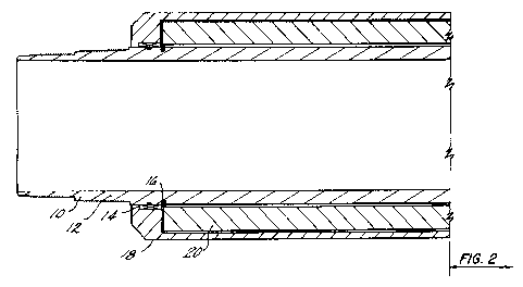
Referring to FIGURES 1-6, a first embodiment of the invention is illustrated.
This embodiment employs the motor-driven hydraulic pump arrangement as the
fluid
moving component.
BOT 284-12103-US
FDC&C 98-1209 4
CA 02270851 2004-03-18
Referring first to FIGURE 1 and moving sequentially through FIGURE 6, the
invention comprises electronics housing 12 having preferably an uphole premium
thread connection for connecting the system of the invention to a string of
pipe (not
shown). Electronics housing 12 supports electronics package 20 within an
annular
space 22 preferably filled with nitrogen and which is defined radially
inwardly by
housing 12 and radially outwardly by electronics cover 18. The gas contained
in the
space 22 is maintained therein by a seal 14 and snap ring 16 at the uphole end
of the
electronics cover 18 while the downhole end of the cover 18 is sealed by
premium
threaded connections which connect the electronics sub to the intermediate sub
24. As
is readily appreciated from a review of the drawing FIGURE 2, electronics
housing 12
is connected to intermediate sub 24 by preferably a premium thread 26 at the
radially
inward extent thereof, while the cover 18 is connected to intermediate sub 24
by a
premium threaded connection 28.
Intermediate sub 24 is employed for manufacturability reasons and supports a
through bore 30 having a connector part 32 at the uphole end thereof which
preferably
is constructed to receive a Kemlomconnector (not shown). Bore 30 provides
passage
for a current carrying conduit (not shown) to power the pump and solenoid dump
valve
discussed hereunder.
Attached at the downhole end of intermediate sub 24 by preferably a premium
threaded connection 34 is pump housing 36. Pump housing 36 extends downhole to
connect with a cylinder sub 96 of a conventional surface controlled subsurface
safety
valve (SCSSV) by preferably a premium threaded connection 98. Pump housing 36
sorzs4-~z~os-us * trade-mark
FDC&C 98-1209
CA 02270851 2004-03-18
contains in an annular space 38, between it and compensator piston 40, which
space 38
is sealed by a large dynamic seal 42, retained by retainer 44 and by small
dynamic seal
52, retained by manifold 54. Also contained in the annular space 38 are motor
46
connected to hydraulic pump 48 which then is connected to discharge connector
SO and
mounted to manifold 54. Annular space 38 is, in a preferred embodiment, also
the
reservoir for the hydraulic fluid supply employed to open the conventional
components
of the SCSSV. The space 38 contains the components noted as well as the
manifold 54
to advantageously bathe the components in the hydraulic fluid in a preferred
embodiment.
Significant benefits are realized by placing all of the components noted
directly
in the reservoir space 38. These benefits include reduction of length of the
tool (more
than one function contained in a single space), longevity increase of the
bathed
components (no deleterious effects from well bore fluids) and the ability to
use more
economical materials such as stainless steel instead of expensive materials
such as
inconel which would be necessary if the manifold were in contact with wellbore
fluids.
Space 38 is pressure compensated to wellbore pressure by compensating piston
40
which employs a large end and a small end corresponding to the large and small
seals
identified above to render the piston dynamic. Preferably seal 42 is a spring-
loaded
Teflon seal, commercially available from Greene, Tweed & Co. and seal 52 is a
spring-
loaded Teflon seal, commercially available from Greene, Tweed and Co. A
conventional elastomeric material may be substituted for dynamic sealing.
Motor 46 is preferably a DC brushless type motor which is available
BOT 284-12103-US
FDC&C 98-1209 * trade-mark 6
CA 02270851 1999-06-24
commercially from many sources. Hydraulic pump 48 is a radial piston type pump
and
is also commercially available from many sources.
Referring to FIGURE 3, pump 48 is preferably threadedly connected to
discharge connector :50 so that pressurized discharge fluid from pump 48 is
transferable
through manifold 54 to the honed seal bore 70 of the conventional SCSSV. In
the
cross-section views of FIGURE 3 and FIGURE 13, it is possible to view recess
56
having metal seal bore 58. Recess 56 connects to fluid port 62 for
communication
through manifold 54 to fluid hone bore 70. Referring to FIGURE 13 directly,
other
aspects of manifold 54 are illustrated.
In FIGURE 13 the manifold 54 is illustrated from the uphole end. Recess 56 is
visible as is port 62 both of which are at the 12 o'clock position on the
drawing.
Important to the invention is solenoid dump valve port 64 which accepts in a
sealing relationship, a solenoid actuated normally open dump valve 65 which is
commercially available from the Lee Company. A representative illustration of
a dump
valve as employed in the invention is depicted in FIGURE 14. Cross channel 66
is a
fluid connection between port 62 and port 64 and allows the safety valve to
close if the
dump valve opens due to an interruption of power. Operation of this feature
will be
discussed more fully hereinafter. The manifold is bolted to the sleeve using
preferably
three points about 120° apart. At these points 72, are holes to accept
bolts 73 secured
to the sleeve preferably by "T" receptacles therein. More specifically, and
referring to
FIGURE 15, the sleeve ~s machined radially from the outside diameter thereof
to form
°T" shaped slots of a dimension sufficient too receive a bolt head and
part of its shank
BOT 284-12103-US
FDCBcC 98-1209 ')
CA 02270851 1999-06-24
and secure the bolts against axial movement. The remainder of the shanks of
each
connection point are threaded into the manifold 54 at the indicated holes 72.
A pair of
nuts on each shank are preferably employed to lock the spacing of the manifold
from
the sleeve.
Referring again to FIGURE 13, nine more holes are apparent, Five of these are
indicted by numeral 74 and are preferably equidistantly spaced on a six-hole
pattern.
The position of the sixth hole would be located between the pump discharge
port recess
56 and the solenoid dump valve port 64. In lieu of the sixth hole, four holes
76 are
provided around the port area. Each of the nine holes are preferably counter
sunk as
illustrated. Each of the nine holes are intended to receive bolts to secure
the manifold
to the conventional SCSSV. The four bolts 74 ensure a pressure tight
connection in the
area defined by the o-ring groove 68. It should be noted that in reservoir 38
a sleeve 39
is preferably installed to take up space so that the volume of fluid in the
reservoir can
be reduced. The sleeve is preferably aluminum. The reduction is not necessary
but is
preferred to reduce cost associated with increased piston sleeve 48 travel
from
hydraulic fluid thermal expansion. The fluid displacement provided by the
large
annular piston on the piston sleeve 40 provides for the thermal expansion of
the
hydraulic safety valve and balances the reservoir pressure to the tubing
pressure thus
requiring that the pump discharge needs only be the differential necessary to
compress
the power spring, the pump does not have to overcome the tubing side pressure.
The
back pressure spring provides a positive fluid reservoir pressure required to
move the
V. I
piston sleeve 38 in the dynamic mode while the safety valve is opening in the
case of
BOT 284-12103-US
FDC&C 98-1209
CA 02270851 1999-06-24
low (atmospheric) tubing pressure. The load on the back pressure spring is
dependent
on the static and dynamic frictional characteristics of the large and small
dynamic seals
42, 52 and the area of the annular piston created between the two. In the
preferred
embodiment the spring is approximately 280 pounds load for about 25 psi in the
reservoir. This positive pressure will also keep wellbore fluids and gases
from
migrating into the reservoir since the differential pressure is higher in the
reservoir.
In operation, electronics package 20 delivers a potential to normally open
solenoid dump valve 80 to close the same. Dump valve 80 is preferably a
solenoid
operating pilot valve, commercially available from Lee Company. With dump
valve 80
closed, cross channel 66 is closed and will not bleed off pressure from the
fluid hone
bore 70 of the conventional SCSSV. Thus, pressure generated by pump 48 is
transmitted to the SCSSV to open the same. Upon any interruption in power to
the
dump valve 80, it returns to its normally open position and dumps the fluid
pressure
back to the reservoir and the SCSSV closes. Assuming that power remains at
dump
valve 80, the valve remains closed indefinitely. Upon a signal from the
surface,
electronics package 20 directs motor 46 to turn pump 48 and generate
increasing
pressure within inlet 70. As pressure increases, the conventional safety valve
will open.
When a particular degree of openness (usually fully open)of the safety valve
is
achieved as measured by a pressure sensor in the inlet, a proximity sensor on
the
flapper valve, a counter on the motor, etc., the motor is directed to stop
moving and to a
discharge check valve in the manifold at 62 will hold pressure in the system.
The
SCSSV is closeable by cutting power to dump valve 80 causing it to open and
dump the
BOT 284-12103-US
FDC&C 98-1209
CA 02270851 1999-06-24
fluid pressure in bore 70. It should be noted that a significant benefit of
the present
invention is that the SCSSV will close at any state of opening, immediately
upon the
dump valve opening. A full stroke is not necessary (i.e. some prior art
requires that
valve be completely open before closing is possible).
In an alternate embodiment of the invention, referring to FIGURES 7-12 the
motor 46, pump 48 and sleeve 39 are replaced by a reciprocating positive
displacement
solenoid plunger pump 110. Referring specifically to FIGURE 9, the solenoid
pump
110 is illustrated in position within the tool as are all of the other
components (which
were not specifically excluded above) of the foregoing embodiment. These are
in the
same places and have the same function. This embodiment of the invention
merely
employs an alternative means for causing fluid pressure to rise in inlet 70.
Changes
exist in two components of the device in this embodiment: 1) the compensating
piston
is preferably constructed of a non-magnetic material to avoid a reduction of
the field
(employed in the operation of the solenoid) that occurs when a magnetic
material is
1 S employed as the compensating piston. Inconel is a preferred choice for the
substitute
material of the compensating piston; and 2) the discharge connector 50' is
distinct from
discharge connector 50. This is due to the pump outlet and the function served
by the
connectors 50, 50'. In the motor/pump first embodiment, the discharge
connector
preferably is threaded into pump 48 and serves to physically hold the pump and
the
motor. In the second embodiment, the discharge connector 50' mounts as in a
honed
bore 112 and seals therein with o-ring 114 but is not fixedly attached.
Rather, in a
preferred arrangement for the second embodiment, discharge connector 50' is
free to
BOT 284-12103-US
FDC&C 98-1209 1 ~
CA 02270851 1999-06-24
move in the bore 112 and the solenoid pump is fixed to the manifold 54 only by
the T-
bolts described above. In other respects the two embodiments are identical.
The solenoid pump embodiment employs a horseshoe wound solenoid to
activate an integral plunger pump. More specifically, the armature of the
solenoid is a
pie shaped section of a ring. The section is approximately 1/4 to 1/3 of the
ring and
includes sides of the pie section at about 45 degrees. The rest of the ring is
wound to
create the coils of the electromagnet in a direction parallel to the
centerline of the ring.
When the solenoid is energized, the gap of the pump closes compressing four
springs
and is the inlet stroke of the pump. When the coil is not energized, the
springs extend
to their normal length and the fluid that had been taken up in the inlet
stroke of the
pump is expelled under pressure. The solenoid pump is manufactured
commercially by
Sub Tech International (formally known as BEI Technology).
In a third embodiment of the invention, referring to Figures 16-19, a modified
configuration of the invention is disclosed. For clarity, elements that are
substantially
1 S similar will employ identical names as the foregoing and are distinguished
therefrom by
distinct numerals. Identical components retain the numerals as introduced
hereinabove.
It is also important to note that in Figures 16-19 the tool is shown in one
position
above the centerline and a second position below the centerline.
Beginning with Figure 16 and proceeding seriatim, electronics housing 120 is
connectable to an uphole string (not shown). Electronics housing 120 supports
electronics package ~0 within an annular space 22 which preferably is nitrogen
filled.
The space 22 is defined by an outer surface of housing 120 and by an inner
surface of
BOT 284-12103-US
FDCdtC 98-1209 11
CA 02270851 1999-06-24
an electronics cover~20. Sealing of the preferred nitrogen gas is by a seal 14
at the
uphole end of cover :20 and a premium thread 28 at the downhole end thereof. A
distinguishing feature of this embodiment over the foregoing embodiment is
that the
premium thread 28 mates back up with the electronics housing 120 whereas in
the
foregoing embodiments it mated with intermediate sub 24. Electronics housing
120
further provides conductor conduit 122 which links annular space 22 and
therefore
electronics package 20 to high pressure connector 124 (preferably a Kemlon
connector).
The connector 124 is inserted into an intermediate sub 126 and is sealed with
preferably two O-rings 128 and 130. Connector 124 is retained in intermediate
sub 126
by connector retainer 132 which is threadedly connected to intermediate sub
126.
Connector retainer 132 further includes an axial bore 134 for passage of
conductors (not
shown). Preferably two connectors are employed. This can be ascertained by
review of
Figure 16A.
Intermediate sub 126 provides a through bore 30 which provides passage for
current
carrying conductors (not shown) to the motor and pump and other electrical
components. Housing 120 is connected to intermediate sub 126 at premium
threaded
connection 26 and threaded connection 136. On the downhole end of intermediate
sub
126, it is threaded by connected and sealed to pump housing 36 at premium
thread 34.
Seal 140, preferably spring loaded Teflon seal is commercially available from
Greene-
Tweed & Company.. Seal 140 rides against compensator piston 40 to seal
hydraulic
fluid chamber 38 while piston 40 works to pressure compensate the chamber 38
as in
BOT 284-12103-US
FDCBcC 98-1209 12
CA 02270851 1999-06-24
the foregoing embodiments. A back pressure spring 138 is preferred to assist
in
manufacture of the invention and keeps the piston urged against the hydraulic
fluid in
space 38 while the tool is at the surface.
Also within space 38, and bathed by the hydraulic fluid contained therein, is
solenoid plunger pump 110 which is identical to that described in the second
embodiment hereof. Moreover, the pump operates identically to the foregoing
and
pumps fluid to manifold 144 through union 142. Fluid pumped to manifold 144 is
subsequently urged into the surface controlled subsurface safety valve
components (not
shown - conventional) to open the same in a manner known to the art.
Since it is desirable as described above that manifold 144 be bathed in
hydraulic
fluid, piston 40 is sealed downhole of manifold 144 by seal 146 and pump
housing 36
is sealed by premium threaded connection 98. It will be appreciated from the
drawing
Figure 18 that pump housing 36 is connected at 98 to RHN sub 148, which sub is
employed in the invention in order to allow fluid to go from a single output
to an
annular fluid chamber created by RHN sub 148 and cylinder sub 152 to allow
hydraulic
fluid to go to one or more pistons which are located in cylinder sub 152. Seal
146 also
terminates against R1KN sub 148 which in a preferred embodiment includes wiper
150
to maintain piston 40 in a clean condition thus prolonging the life of seal
146. Finally,
cylinder sub 152 (Figure 19) is attached to RHN sub 148 by premium thread 154.
Cylinder sub 152 functions to allow fluid from the output of the pump to
access
conventional rod pistons) (which actuate the SCSSV) connected as its downhole
end to
an otherwise conventional SCSSV. It will be appreciated that the high pressure
BOT 284-12103-US
FDCBcC 98-1209 13
CA 02270851 2004-03-18
hydraulic fluid conduit 156 continues from manifold 144 to the SCSSV (not
shown) to
supply high presswe hydraulic fluid thereto.
Taming now to Figures 18A and 18B, the manifold 144 of this embodiment of
the invention is illustrated in cross-section as indicated by cross-section
lines 18A-18A
and 18B-18B in Figure 18. Manifold 144 is similar to the foregoing embodiments
but
in this embodiment is configured to accept electronics designed to provide
additional
information while maintaining the desired function of the manifold as
described
hereinabove.
Referring directly to Figure 18A, one will recognize from the foregoing
description holes 74 and 76 as well as O-ring gTOOVe 68. New to the view is
openings
160, 162, 164 and 166. These are positioned to optimize function of the
manifold and
provide fluid continuity to various structures mounted on the uphole side of
manifold
144. Referring then to Figwe 18B, the uphole side of manifold 144 is
illustrated. As
one will appreciate, holes 72, 74 and 76 are illustrated as have been
described
hereinbefore. Also illustrated are a piloting solenoid port 64 which is in
fluid
connection with opening 160 to supply high presswe hydraulic fluid to the
SCSSV.
Adjacent the solenoid valve port 64 is a port 168 for a transducer such as a
BEI
EDCLIFF transducer which is commercially available from BEI EDCLIFF. The
transducer provides information regarding the presswe of the fluid in the
control line
which holds open the flapper valve of the conventional SCSSV. Such information
is
valuable to determine the degree of openness of the flapper. Union port 62 is
as in the
previous embodiments, and a port 170 for a second transducer having one or
more
BOT 284-12103-US * trade-mark 14
FDCRC 98-1209
CA 02270851 1999-06-24
capabilities e.g. differential pressure measurement, pressure measurement,
etc. which
preferably monitors tubing pressure. The preferred transducer is such as a
Sensotec
transducer which is commercially available from Sensotec. Port 170
communicates
with opening 166 port 62 with opening 164 and port 168 communicates with
opening
162.
While preferred embodiments have been shown and described, various
modifications and substitutions may be made thereto without departing from the
spirit
and scope of the invention. Accordingly, it is to be understood that the
present
invention has been described by way of illustration and not limitation.
BOT 284-12103-US
FDC&C 98-1209 15