Sélection de la langue

Search

Sommaire du brevet 2271171 

Énoncé de désistement de responsabilité concernant l'information provenant de tiers

Une partie des informations de ce site Web a été fournie par des sources externes. Le gouvernement du Canada n'assume aucune responsabilité concernant la précision, l'actualité ou la fiabilité des informations fournies par les sources externes. Les utilisateurs qui désirent employer cette information devraient consulter directement la source des informations. Le contenu fourni par les sources externes n'est pas assujetti aux exigences sur les langues officielles, la protection des renseignements personnels et l'accessibilité.

Disponibilité de l'Abrégé et des Revendications

L'apparition de différences dans le texte et l'image des Revendications et de l'Abrégé dépend du moment auquel le document est publié. Les textes des Revendications et de l'Abrégé sont affichés :

  • lorsque la demande peut être examinée par le public;
  • lorsque le brevet est émis (délivrance).
(12) Demande de brevet: (11) CA 2271171
(54) Titre français: SUPPORT POUR AIGUISAGE D'OUTILS TRANCHANTS
(54) Titre anglais: JIG FOR GRINDING SHARP-EDGED TOOLS
Statut: Réputée abandonnée et au-delà du délai pour le rétablissement - en attente de la réponse à l’avis de communication rejetée
Données bibliographiques
(51) Classification internationale des brevets (CIB):
  • B23Q 03/06 (2006.01)
  • B24B 03/36 (2006.01)
  • B25B 11/02 (2006.01)
(72) Inventeurs :
  • JANSSON, TORGNY (Suède)
(73) Titulaires :
  • TORMEK AB
(71) Demandeurs :
  • TORMEK AB (Suède)
(74) Agent: NORTON ROSE FULBRIGHT CANADA LLP/S.E.N.C.R.L., S.R.L.
(74) Co-agent:
(45) Délivré:
(22) Date de dépôt: 1999-05-06
(41) Mise à la disponibilité du public: 1999-11-13
Licence disponible: S.O.
Cédé au domaine public: S.O.
(25) Langue des documents déposés: Anglais

Traité de coopération en matière de brevets (PCT): Non

(30) Données de priorité de la demande:
Numéro de la demande Pays / territoire Date
9801669-4 (Suède) 1998-05-13

Abrégés

Abrégé anglais


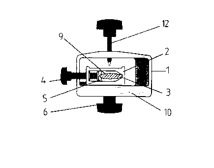
Jig for grinding sharp-edged tools. The jig consists of a housing (1) in the
form of a
casing designed with a passage running through it whose at least one end (10)
is flat, plus a seat
(2), also in the form of a casing designed with a passage running through it,
located in the
passage of the housing and lockable (6) in this housing in an inclined
position in relation to the
passage in the housing, whereby the seat (2) is provided with a clamping
device (4) for firmly
holding a tool that is to be ground so that it extends through the passage of
the seat, and that the
seat (2) has such a length that one end of it extends out beyond the housing
at the flat end (10) of
the housing.

Revendications

Note : Les revendications sont présentées dans la langue officielle dans laquelle elles ont été soumises.


4
Claims
1. Jig for grinding sharp-edged tools characterised in that it consists of a
housing (1) in the form of a casing designed with a passage running through it
whose at least one
end (10) is flat, plus a seat (2), also in the form of a casing designed with
a passage running
through it, located in the passage of the housing and lockable (6) in this
housing in an inclined
position in relation to the passage in the housing, whereby the seat (2) is
provided with a
clamping device (4) for firmly holding a tool that is to be ground so that it
extends through the
passage of the seat, and that the seat (2) has such a length that one end of
it extends out beyond
the housing at the flat end (10) of the housing.
2. Jig for grinding sharp-edged tools characterised in that it consists of a
housing (1) in the form of a casing designed with a passage running through it
where at least one
end (10) is flat, plus a seat 2' located in the passage of the housing and
having an open channel
facing towards the interior of the housing in which the tool (9) that is to be
ground is intended to
lie and be held in place with the help of locking device (12) that abuts the
tool, and that the seat
(2') can be locked in the passage of the housing.
3. Jig according to claims 1 or 2 characterised in that the passage of the
housing (1) has a rectangular cross-section and that the seat (2, 2') can be
locked against one
long side of the passage as seen in cross-section.
4. Jig according to claims 1 or 3 characterised in that the passage of the
seat
(2) has a rectangular cross-section whose one short side is provided with a
notch (3) and whose
other short side supports a screw (4) threaded in the seat whose inner end is
provided with a
counterstay (5) with a notch, whereby the tool (9) with its edges running in
the respective notches
is locked in the seat (2) with the help of the screw (4).
5. Jig according to claim 4 characterised in that the clamped tool (9)
extends along the mid-line of the seat (2) when seen at right angles to the
direction of the
clamping.
6. Jig according to claims 2 or 4 characterised in that the open channel of
seat (2') has a flattened V-shape and that the tool (13, 14) is held in place
in the channel with the
help of a screw (12) whose end is directed towards the point of the V and that
acts on the tool.
7. Jig according to claim 6 characterised in that the end of the screw (12) is
pointed (15).

Description

Note : Les descriptions sont présentées dans la langue officielle dans laquelle elles ont été soumises.


CA 02271171 1999-OS-06
Jig for grinding sharp-edged tools
The present invention concerns a jig for grinding sharp-edged tools such as
chisels,
gouges, parting tools, etc.
The invention makes it possible to even grind bevelled chisels with an oval
cross-
section, which are normally very difficult to grind with precision, as the
convex underside of the
chisels cannot rest against the grinding support in an exact and stable
manner.
With the help of the invention, the oblique angles of the tool are adjustable
in a
continuously variable manner for grinding.
These opportunities for grinding sharp-edged tools are possible through the
invention having acquired the characteristics specified in the claims.
A jig with such an extensive range of functions is not previously known.
The invention will be described in the form of examples with reference to the
drawings, where Fig. 1 shows the jig according to the invention including the
housing with the
casing for firmly holding chisels with an oval cross-section, Fig. 2 shows the
invention with the
open V-shaped seat for grinding tools with straight lips, Fig. 3 shows the
invention according to
Fig. 2 with a firmly clamped gouge, Fig. 4 shows the seat included in the
invention in
perspective, Figs. 5 and 6 show the invention used for grinding a bevelled
chisel with an oval
cross-section, Figs. 7 and 8 show the invention used for grinding a gouge with
a straight lip and
with the use of the open seat, Figs. 9, 10 and 11 show the invention used for
grinding a curved
or cam-shaped lip, Fig. 12 shows an angle marking on the casing and Fig. 13
shows how the
invention with the help of this angle marking can be used when adjusting the
inclination of the lip
of the tool.
Fig. 1 shows an end view of the jig according to the invention, which includes
a
housing 1 essentially rectangular in cross-section. Housing 1 accommodates a
similarly
rectangular in cross-section enclosed seat 2, one short side of which is
provided with a notch 3.
The side opposite the said short side of seat 2 has a screw 4 running all the
way through it and
threaded in the seat whose inner end is provided with a counterstay 5 that has
a notch. The seat 2
can be removed from the housing 1 but can also be locked in place in the
housing with the help
of a locking screw 6. The treads of the locking screw 6 grip with equivalent
threads in a hole 7
(Fig. 4) in the seat and press against the flat inside 8 of housing 1 when
locking screw 6 is
tightened. The tool 9 is inserted into the seat and is placed with the edges
running in notch 3 and
the notch of the counterstay 5 and locked in the seat with the help of screw
4. In the situation
shown, the seat 2 and thus the tool 9 extend at right angles out from at least
the one flat end 10 of

CA 02271171 1999-OS-06
2
the housing. This right-angled position can be taken up automatically by the
seat 2 pressing
against a shoulder 11 in the passage of the housing 1 when the locking screw 6
is turned around
its centre. By loosening the seat 2 from the housing using the locking screw
6, the seat can be
turned to the angled position required and once again locked against the
housing 1 with the help
of the locking screw 6.
As is evident from the following, seat 2 extends somewhat outwards from the
flat
end 10 of the housing 1.
Figs. 2 and 3 show the invention when the enclosed seat 2 has been replaced
with an
open seat 2'. Like enclosed seat 2, open seat 2' can be turned and locked in
position against the flat
aside 8 of housing 1. As is evident from Figs 2 and 3, open seat 2' has a
flattened V-shape. A
screw 12 threaded forwards and backwards in housing 1 is directed at the point
of the V, i.e. the
bottom of the open channel. By using this open seat 2', it is possible with
the help of the invention
to grind tools such as gouges 13 or parting tools 14 or chisels or sinular. As
the free end of screw
12 ends in a point this is located co-axially with locking screw 6, it is
possible to pivot the seat 2'
~~ ~e tool in relation to the housing 1. Fig. 4 shows the enclosed seat 2 with
a threaded hole 16
for screw 4 and, as previously mentioned, the threaded hole 7 for locking
screw 6.
Figs. 5 and 6 show the grinding of a bevelled chisel with the help of the
invention.
In the figures, 17 designates a grinding wheel and 18 a so-called universal
support which is
attached to the base of the grinding wheel and as such is fixed in relation to
the rotating grinding
wheel. Tool 7 is clamped firmly in housing 1 via seat 2 as described
previously and, with the
help of the latter, an oblique adjustment of the tool in relation to the
housing is set, where the
oblique adjustment determines the inclination of the cutting edge. The cutting
angle of the tool is
determined by displacement of the universal support 18 as indicated by the
arrows Pl (Fig. 5).
During grinding, the flat and broad end 10 of the housing 1 abuts the
universal joint 18 while the
jig rests against the support 18 with the "underside" of seat 2, i.e. by being
held with the end 10
pressed against the universal support 18, the housing guides the tool the
whole time in a straight
line movement, see arrows Pz (Fig. 6). To grind the lip on the other side of
the tool 9, the whole
jig is turned 180°. The tool is held completely symmetrically in seat
2, i.e. at the same distance
from both broad ends of the seat, which means that repeating the adjustment
for grinding the
other side of the lip is not necessary.
Figs. 7 and 8 show the grinding of a gouge with the help of the invention. In
this
case, seat 2' is used, which as is evident from the figures, does not extend
outwards from the flat
end 10 of housing 1. The gouge is clamped firmly as is shown in Fig. 3. As
before, the flat end

CA 02271171 1999-OS-06
3
of the housing 1 is supported against the universal support 18 during
grinding, while the
underside of the gouge abuts the support 18. During grinding, housing 1 thus
guides the direction
of the tool 13 towards the grinding wheel 17 while the underside of the gouge
makes it possible
to tilt the gouge during grinding to thereby grind the whole lip (compare the
arrows P3 in Fig. 8.
5 As was mentioned earlier in connection with Figs. 5 and 6, the angle of
cutting is adjusted by
displacement of the universal support 18 (arrow Pl).
Figs. 9 - 11 show how it is possible to grind a lip with a curved or cam-shape
with
the help of the invention. The tool 9 is clamped firmly in the jig in seat 2
and the starting point
is, for example, that shown in Fig. 9. By pivoting the jig against the support
18 around the left-
10 hand edge of the housing at the same time as the jig is displaced with the
seat 2 resting against
support 18, as in the shown example, the originally straight lip will be
ground to a curved shape.
By turning the jig with the tool and performing the same movement but in a
reverse direction, the
other side of the lip of the tool can also be ground.
Fig. 12 shows the seat 2 provided with a graduated scale up to 40°,
whereby the
symbol with the obliquely ground end of a tool and the angle marking s explain
the meaning of
the scale. Fig. 13 shows more clearly the seat 2 located in housing 1.
As is shown in the figures, housing 1 is shaped with a narrow side inclined
"backwards", i.e. in a direction towards the operator when handling the jig.
The design is
conditioned by giving the seat sufficient free-play when being pivoted as well
as keeping the
housing as small and easy to handle as possible.

Dessin représentatif
Une figure unique qui représente un dessin illustrant l'invention.
États administratifs

2024-08-01 : Dans le cadre de la transition vers les Brevets de nouvelle génération (BNG), la base de données sur les brevets canadiens (BDBC) contient désormais un Historique d'événement plus détaillé, qui reproduit le Journal des événements de notre nouvelle solution interne.

Veuillez noter que les événements débutant par « Inactive : » se réfèrent à des événements qui ne sont plus utilisés dans notre nouvelle solution interne.

Pour une meilleure compréhension de l'état de la demande ou brevet qui figure sur cette page, la rubrique Mise en garde , et les descriptions de Brevet , Historique d'événement , Taxes périodiques et Historique des paiements devraient être consultées.

Historique d'événement

Description Date
Inactive : CIB expirée 2012-01-01
Inactive : CIB de MCD 2006-03-12
Le délai pour l'annulation est expiré 2005-05-06
Demande non rétablie avant l'échéance 2005-05-06
Réputée abandonnée - omission de répondre à un avis sur les taxes pour le maintien en état 2004-05-06
Inactive : Abandon.-RE+surtaxe impayées-Corr envoyée 2004-05-06
Inactive : Page couverture publiée 1999-11-19
Demande publiée (accessible au public) 1999-11-13
Lettre envoyée 1999-08-10
Inactive : Transfert individuel 1999-07-12
Modification reçue - modification volontaire 1999-07-12
Inactive : CIB attribuée 1999-06-25
Inactive : CIB en 1re position 1999-06-25
Inactive : Lettre de courtoisie - Preuve 1999-06-15
Inactive : Certificat de dépôt - Sans RE (Anglais) 1999-06-10
Exigences de dépôt - jugé conforme 1999-06-10
Demande reçue - nationale ordinaire 1999-06-07

Historique d'abandonnement

Date d'abandonnement Raison Date de rétablissement
2004-05-06

Taxes périodiques

Le dernier paiement a été reçu le 2003-04-14

Avis : Si le paiement en totalité n'a pas été reçu au plus tard à la date indiquée, une taxe supplémentaire peut être imposée, soit une des taxes suivantes :

  • taxe de rétablissement ;
  • taxe pour paiement en souffrance ; ou
  • taxe additionnelle pour le renversement d'une péremption réputée.

Les taxes sur les brevets sont ajustées au 1er janvier de chaque année. Les montants ci-dessus sont les montants actuels s'ils sont reçus au plus tard le 31 décembre de l'année en cours.
Veuillez vous référer à la page web des taxes sur les brevets de l'OPIC pour voir tous les montants actuels des taxes.

Historique des taxes

Type de taxes Anniversaire Échéance Date payée
Taxe pour le dépôt - générale 1999-05-06
Enregistrement d'un document 1999-07-12
TM (demande, 2e anniv.) - générale 02 2001-05-07 2001-05-04
TM (demande, 3e anniv.) - générale 03 2002-05-06 2002-04-09
TM (demande, 4e anniv.) - générale 04 2003-05-06 2003-04-14
Titulaires au dossier

Les titulaires actuels et antérieures au dossier sont affichés en ordre alphabétique.

Titulaires actuels au dossier
TORMEK AB
Titulaires antérieures au dossier
TORGNY JANSSON
Les propriétaires antérieurs qui ne figurent pas dans la liste des « Propriétaires au dossier » apparaîtront dans d'autres documents au dossier.
Documents

Pour visionner les fichiers sélectionnés, entrer le code reCAPTCHA :


Pour visualiser une image, cliquer sur un lien dans la colonne description du document. Pour télécharger l'image (les images), cliquer l'une ou plusieurs cases à cocher dans la première colonne et ensuite cliquer sur le bouton "Télécharger sélection en format PDF (archive Zip)" ou le bouton "Télécharger sélection (en un fichier PDF fusionné)".

Liste des documents de brevet publiés et non publiés sur la BDBC .

Si vous avez des difficultés à accéder au contenu, veuillez communiquer avec le Centre de services à la clientèle au 1-866-997-1936, ou envoyer un courriel au Centre de service à la clientèle de l'OPIC.


Description du
Document 
Date
(aaaa-mm-jj) 
Nombre de pages   Taille de l'image (Ko) 
Dessin représentatif 1999-11-18 1 6
Abrégé 1999-05-05 1 17
Description 1999-05-05 3 168
Revendications 1999-05-05 1 55
Dessins 1999-05-05 6 90
Certificat de dépôt (anglais) 1999-06-09 1 165
Courtoisie - Certificat d'enregistrement (document(s) connexe(s)) 1999-08-09 1 139
Rappel de taxe de maintien due 2001-01-08 1 112
Rappel - requête d'examen 2004-01-06 1 123
Courtoisie - Lettre d'abandon (requête d'examen) 2004-07-14 1 166
Courtoisie - Lettre d'abandon (taxe de maintien en état) 2004-07-01 1 175
Correspondance 1999-06-14 1 30