Note : Les descriptions sont présentées dans la langue officielle dans laquelle elles ont été soumises.
- 1 ~-
PROCESS AND DEVICE FOR SIMULTAN'.EOUSLY DRILLING AND LINING A
HOLE
The present invention relates to a method for drilling, in
particular impact drilling or rotary percussion drilling,
and lining holes in soil or roc:k material, wherein a drill
hole is formed by means of a drill bit mounted on a drill
rod assembly by a percussive and/or rotary movement and a
lining is formed by means of a jacket tube. Furthermore, the
present invention relates to a device for drilling, in
particular impact drilling or rotary percussion drilling,
and lining holes in soil or roc:k material, wherein a drill
bit mounted on a drill rod asse~:nbly makes a drill hole by a
percussive and/or rotary movement.
Methods and devices of this type, for drilling and, in
particular, impact drilling or rotary percussion drilling
and subsequently lining holes in soil or rock material are
known in various configurations. Thereby, a hole or a bore
optionally extending over a geat length is formed by aid of
a drill bit mounted on a drill rod assembly, the drill hole
being formed by a percussive and/or rotary movement. In
rotary percussion drilling, i~he drill bit after each
percussive stress exerted on ths: same, usually is rotated by
a defined angle and acted upon anew by means of a percussion
?5 tool, wherein, by the alternate displacement of the drill
bit in the direction of rotation and the intermittent
percussion, the material is systematically disintegrated and
broken out on the surface covered by the drill bit during
the rotary movement. In order to prevent material from
breaking into the drill hole optionally extending over a
great length and/or provide fo:r an essentially smooth and
plane lining after completion of the bore, it was, for
instance, proposed to use an accordingly sturdily designed
jacket tube while exerting the percussive movement on the
drill bit, for instance, via i:he jacket tube, the jacket
tube, strictly speaking, thus constituting a part of the
drilling or advance working device. It is immediately
apparent that such a jacket rube has to be accordingly
sturdy and thick-walled in order to introduce the high
CA 02271655 1999-OS-11
- 2 ~-
impact forces required, from which follows that an
accordingly increased cross section must be drilled in order
to take into account the wall thickness of the jacket tube.
Such a working cross section aua~mented by the wall thickness
of the jacket tube involves an accordingly extended period
of time for producing a bore, in particular with hard rock,
at the same time calling for an accordingly larger and
sturdily designed drill bit.
Instead of using a jacket tube for introducing the impact
forces, methods have, moreover,, become known, in which a
plurality of time-consuming operating steps serve to remove
the drill bit from the drill hole after completion of the
drill hole and to insert a lining or jacket tube into the
drill hole after this. It is immediately apparent that such
a mode of procedure is applicable only in those cases in
which the breaking in of material into the completed drill
hole can be excluded for sure, wherein, moreover, an
accordingly increased cross section must, of course, be
?0 drilled in order to render feasible the subsequent insertion
of a lining or jacket tube. In order to be able to insert
such a lining or jacket tube having a great length, that
tube must again have a relatively large wall thickness so as
to render feasible its safe introduction. A drill bit
matching with the dimensions of the jacket tube and thus
having a relatively large diameter must, therefore, be used
also in that case.
After having inserted the lin:_ng or jacket tube, a roof bolt
may, for instance, be inserted into the jacket tube and,
additionally or alternatively, also an accordingly rapidly
setting material for solidifying the surrounding material.
Alternatively, such a lining mar serve to accommodate ducts
or the like or, when providing perforations, be used for
carrying off liquids and hence for drainage.
Departing from a method for drilling, in particular impact
drilling or rotary percussion drilling, and lining holes in
soil or rock material, the present invention, therefore,
CA 02271655 1999-OS-11
- 3 ~-
aims at further developing with a view to enabling the
insertion of at least one jacket tube substantially
simultaneously with the formation of the drill hole in a
quick and simple manner. Furthermore, it is aimed at
employing a jacket tube or jacket tubes having reduced
dimensions and, in particular, reduced wall thicknesses as
compared to known configurations in order to be able to
minimize the additional expenditures required for the jacket
tubes) during drilling. To so:Lve this object, the method
according to the invention essE~ntially is characterized in
that with the advance movement during drilling at least one
jacket tube coupled with the drill bit is introduced into
the drill hole in the axial direction by means of the drill
bit by tensile action and that after completion of the
drilling procedure the drill bit: is removed from the jacket
tube at least partially togE~ther with the drill rod
assembly. By introducing, according to the invention, a
jacket tube coupled with the drill bit into the drill hole
by tensile action merely in the axial direction with the
advance movement during drilling, it is ensured that lining
of the drill hole may be effected already immediately upon
making of the same such that the breaking in of possibly
loose rocks and hence the obstruction of the drill hole can
be safely avoided. By introducing into the drill hole the at
least one jacket tube directly by means of the drill bit by
mere axial action, it is, furthermore, feasible to do with a
very thin-walled jacket tube, since the jacket tube does not
have to absorb and transmit any forces as was the case, for
instance, according to prior ari= wherein impact forces were
exerted onto the drill bit via an accordingly sturdy jacket
tube, and merely must exhibit a sufficient strength in order
to safely avoid bending or a cross sectional reduction
caused by possibly loose rock. In order to ensure the simple
removal of the drill bit together with the drill rod
assembly without changing the position of the jacket tube
within the drill hale after completion of the bore, the
invention, moreover, proposes to remove the drill bit from
the jacket tube at least partially together with the drill
rod assembly. To this end, the c3ri11 bit may, for instance,
CA 02271655 1999-OS-11
CA 02271655 2005-04-07
28664-11
4
be divided into a substantially central part and an outer
part surrounding the central part in a substantially annular
manner such that, upon detachment of the central part, this
main component of the drill bit can be removed from the
drill hole together with the drill rod assembly through the
interior of the at least one jacket tube.
According to a broad aspect, the invention
provides a method for drilling and placing of roof bolts
into holes in soil or rock material, said method comprising:
forming a drill hole by a drill bit mounted on a drill rod
assembly and forming a lining by at least one thin-walled
jacket tube, removing, after completion of the drilling
procedure, the drill bit from the at least one thin-walled
jacket tube together with the drill rod assembly, and with
the advance movement during drilling, the at least one thin-
walled jacket tube coupled at an end facing away from a work
face with the drill bit, divided in a radial direction, is
introduced into the drill hole in the axial direction by the
drill bit only by tensile action and that after the removal
of the drill rod assembly and the drill bit, at least one
roof bolt is introduced into the at least one thin-walled
jacket tube and a filling is realized with a solidifying
material.
According to another broad aspect, the invention
also provides a device for drilling in soil or rock
material, said device comprising a drill bit mounted on a
drill rod assembly for making a drill hole by at least one
of a percussive and a rotary movement, the drill bit being
designed to be divided in a radial direction and that, on an
external periphery of the drill bit on an end facing away
from a work face, at least one thin-walled jacket tube
surrounding the drill rod assembly in radial direction being
positively connected with the drill bit via at least one
CA 02271655 2004-07-13
28664-11
4a
coupling element only for tensile entrainment in a
longitudinal direction of a drill hole.
In order to ensure, during a rotary movement of
the drill bit, that the jacket tubes) coupled with the
drill bit during drilling is nevertheless introduced merely
in the axial direction of the drill hole by tensile action
in the sense of the advance movement, it is additionally
proposed in a preferred manner that the drill bit is
arranged so as to be rotatable relative to the jacket
tube ( s ) .
According to a particularly preferred embodiment,
the method according to the invention is further developed
such that, after the removal of the drill rod assembly and
of the central part of the drill bit, a roof bolt is
introduced into the jacket tubes) and/or a filling is
realized with a solidifying material.
For the simple extraction of the material worked
by means of the drill bit, it is, moreover, proposed in a
preferred manner that worked material is introduced into the
interior of the jacket tubes) via at least one aperture
provided in the region following upon the drill bit and is
extracted from the drill hole in the free space provided
between the jacket tubes) and the drill rod assembly. By
extracting the worked material from the drill hole in the
free space provided between the jacket tube or tubes and the
drill rod assembly, the necessary drill hole cross section
may be further reduced such that the external dimensions of
the drill hole may be adapted substantially to the external
diameter of the outer jacket tube, favourably exceeding the
CA 02271655 2004-07-13
28664-11
4b
same merely by a slight measure.
In order to solve the objects set out above, a
device according to the invention for drilling, in
particular
- 5 -
impact drilling or rotary percussion drilling, and lining
holes in soil or rock material, wherein a drill bit mounted
on drill rod assembly makes a drill hole by a percussive
and/or rotary movement, is essentially characterized in that
the drill bit is designed to be divided in its radial
direction and that, on the external periphery of the drill
bit on the end facing away from the work face, at least one
jacket tube surrounding the dril:L rod assembly is positively
connected with the drill bit via at least one coupling
element for tensile entrainir~ent in the longitudinal
direction of the drill hole. By the drill bit being designed
to be divided in the radial dirs~ction, it can be ensured in
a simple manner upon completion of the drill hole that, for
instance, the central main pare.. of the drill bit may be
removed from the drill hole together with the drill rod
assembly through the jacket tube while the at least one
jacket tube is introduced into the drill hole directly in
the production of the drill hole by tensile entrainment
effected in the longitudinal direction of the drill hole and
?0 remains within the drill hole afaer completion of the drill
hole . In order to ensure that tree jacket tube ( s ) mounted on
the external periphery of the drill bit are acted upon
merely in the axial direction of the drill hole even at a
rotary movement of the drill bit:, it is, moreover, provided
in a preferred manner that the drill bit is rotatably
connected with the jacket tubes) via the coupling element.
With a view to providing particularly simple coupling
between the drill bit and the jacket tube entrained in the
axial direction by the drill bit. at an advance movement, it
is, moreover, proposed in a preferred manner that the
coupling elements are formed by offset peripheral regions of
the drill bit and of the =jacket tube with matching
complementary profiles, optional:Ly by interposing a profiled
annular intermediate member. DuE~ to such offset peripheral
regions, which, for :instance, may be designed in the manner
of steplike elevations and complementary depressions, the
safe entrainment of the jacket tube during the advance
CA 02271655 1999-OS-11
- 6 -
movement of the drill bit will be ensured even with
comparatively thin wall thicknes;;es of the jacket tube.
With a view to providing simple coupling between the drill
bit and the jacket tubes) to he entrained in the advance
movement of the drill bit, it is alternatively proposed that
the coupling elements are formed by a plurality of balls
arranged in recesses provided on the drill bit and having
substantially semi-circular cross sections and complementary
recesses provided on a connection piece of the jacket
tubes) following upon the dril:L bit, as in correspondence
with a further preferred embodiment of the device according
to the invention. By using balls that are arranged in
corresponding recesses both on the drill bit and on the
connection piece of the jacket tube(s), an accordingly
simple connection and coupling b~atween the drill bit and the
jacket tube ( s ) is feasible in the manner of a ball bearing,
thus allowing for an accordingly easy rotatability of the at
least one jacket tube relative t.o the drill bit at a rotary
and/or rotary percussive movement of the drill bit during
the production of a drill hole. According to a particularly
preferred embodiment, it is provided in this respect that
the connection piece of the at T_east one jacket tube and/or
the connection zone of the drill bit are made of metal,
synthetic material or a coated material, wherein matching of
the individual materials both of the coupling elements and
of the recessed connection piecE~ of the jacket tubes) and
the end piece of the drill bit, respectively, is feasible
when using balls of, for in~;tance, metal or synthetic
material. An accordingly easy displacement of the balls into
the recesses provided to recs~ive the coupling elements
formed by the balls may, of: course, be obtained by
introducing a lubricant, for instance, oil.
In order to prevent forces that start to act on the drill
bit at an advance movement, from being introduced into the
jacket tube, which optionally ha;s a very small cross section
or slight wall thickness, and thus possibly causing
deformation of the same, it is, moreover, proposed that the
CA 02271655 1999-OS-11
coupling elements between the drill bit and the jacket
tubes) at least partially are made of a damping material or
are coated with a damping material, as in correspondence
with a further preferred embodiment of the device according
to the invention.
With a view to enabling the simple removal of worked
material in the free space provided between the inner jacket
tube and the drill rod assemb:Ly, whereby an accordingly
small drill hole cross section substantially matching with
the external dimensions of the outer jacket tube may be
safeguarded, it is, moreover, provided in a preferred manner
that the j acket tube ( s ) in its ( their ) end region ( s ) facing
the drill bit comprises) at least one passage opening, in
particular several bores or passage slits uniformly
distributed over the circumference of the jacket tube.
As already indicated above, jacket tubes not only may be
used for the subsequent insertion of a roof bolt and hence,
in general, providing anchorage of objects, but it may, for
instance, also be provided to effect drainage via the
produced drill hole and the jacket tubes inserted therein.
To this end, the invention preferably proposes that the
jacket tube(s), over its (their) total length(s), is (are)
designed to have perforations substantially uniformly
distributed over the periphery.
In order to ensure the simple removal of the central part of
the drill bit after completion of a drill hole, it is,
moreover, proposed in a preferred manner that the drill bit
at least is comprised of a central inner part and an outer
part which are detachably coupled to each other for common
advance movement, the central pa~_t of the drill bit having a
slightly smaller external diameter relative to the internal
diameter of the inner jacket tube. In order to allow for
particularly simple and reliable coupling of the individual
elements of such a multiple-part drill bit, it is, moreover,
proposed in a preferred manner that, with a view to
rotational entrainment, the central inner part of the drill
CA 02271655 1999-OS-11
_ g _.
bit has a cross section deviating from the circular form and
is led out through an appropriate opening of the outer part
of the drill bit.
As already mentioned several times, it is not necessary, due
to the fact that the jacket tube is introduced directly
through the drill bit by actuation in the axial direction
during the advance or drilling movement, to provide a drill
hole diameter strongly enlarged relative to the external
dimensions of the outer jacket or lining tube, as was
necessary according to prior art, in particular, with the
subsequent introduction of a jacket tube. It will,
therefore, do that the external diameter of the outer jacket
tube substantially corresponds to the external dimensions of
the drill bit in the radial direcaion.
Since the jacket tubes employed according to the invention
substantially merely have to resist possibly breaking-in
material and need nat take up ar transmit any forces such
as, for instance, impact for~~es for rotary percussion
drilling, accordingly thin-walled jacket tubes will suffice.
In this context, the invention preferably proposes that the
jacket tubes) has (have) a wall thickness of from 1 to 3 mm
and, in particular, about 2 mm such that it is immediately
?5 apparent that, by providing ths~ jacket tubes, the overall
surface to be worked or drilled need to be increased only
slightly and also an accordingly reduced amount of material
and hence weight will. do for the jacket tube(s).
According to a particularly preferred embodiment, it is
provided that the jacket tubes) is (are) made of metal or
synthetic material, thereby enabling accordingly simple
adaptation to the surrounding conditions and, in particular,
to the soil or rock material in which a drill hole is to be
produced. While a jacket tube made of metal has an
accordingly high mechanical strength, it may, however, be
disadvantageous with such a configuration that loose or
slack soil or rock layers may potentially affect the usually
very thin-walled jacket tube by causing bending or cross-
CA 02271655 1999-OS-11
- g _
sectional contraction of the same, thereby possibly rende-
ring difficult, or completely preventing, the subsequent
removal of the drill. bit and hence the subsequent introduc-
tion of, for instance, a roof bolt. In particular with such
loose soil or rock material, they use of jacket tubes made of
synthetic material and thus ofj'ering a certain flexibility
has proved advantageous, since even in case of temporary
cross sectional changes of the jacket tube(s), the jacket
tubes will reassume their original cross sectional shapes
during further advance of the drill bit taking the same with
it, and the problem-free removal of the drill bit and
optionally the subsequent insertion of a roof bolt will
become readily feasible after completion of the drill hole.
In particular, when using jacls:et tubes made of synthetic
material, the use of coupling Elements of the ball bearing
type as pointed out above is particularly advantageous to
enable free and largely undisturbed rotatability between the
drill bit and the jacket tubes during the rotary or rotary
percussion drilling movement o:E the drill bit, since the
rotary entrainment o.f the jacket tube by the drill bit is to
be regarded as disadvantageous when using jacket tubes made
of synthetic material.
In order to minimize, in particular, in soil or rock layers
?5 comprising readily breaking-in material and thus causing the
frictional forces acting on the jacket tubes to become
especially large, said forces to the major extent possible,
it is proposed according to the invention that two jacket
tubes are arranged substantiall~r concentric with each other
and held at a distance from ea~~h other by means of spacer
elements or stop elements provided in the interspace between
the jacket tubes, preferably on one of the jacket tube
surfaces facing each other. Due to the fact that two jacket
tubes are arranged in a substantially concentric and spaced-
apart manner, damage to the drill rod assembly may be safely
avoided, on the one hand, even in case of overstressing of
the outer jacket tube by breaking-in material and hence
destruction of, or damage to, the same and, by the drill bit
carrying with it only one of the two substantially con-
CA 02271655 1999-OS-11
- 10 ~-
centrically arranged jacket tubas, it is feasible, on the
other hand, to provide for a drill hole lining in which the
drill hole lining external diameter is not constant over the
total length. Such varying external dimensions of the drill
hole lining help to minimize the frictional forces acting on
the jacket tubes, in particular, in regions of reduced drill
hole lining diameters.
In order to safeguard such a te~lescopability, or the sepa-
rate entrainment of each of the two concentrically arranged
jacket tubes, the invention is Essentially characterized in
that at least the externally arranged jacket tube is com-
prised of several parts and, in the region of at least one
junction of neighbouring jacket tube portions, are de-
tachably coupled with the inner tube via a fixation capable
of being uncoupled by the relative rotation of neighbouring
elements, in particular a bayonet catch. The multi-part
design of the externally arranged jacket tube and the
decouplable connectian of neighbouring jacket tube portions
?0 enable one jacket tube portion t:o be entrained after having
undone the fixation of two neighibouring jacket tube portions
with the other jacket tube portion remaining stationary,
thus obtaining a drill hole lining having varying diameters.
In order to ensure complete lining of the drill hole and
concerted entraining of either tile internally located or the
externally located jacket tube portions, the device accor-
ding to the invention preferably is devised such that the
concentrically arranged jacket tubes in at least one end
region each comprise stop elements extending into the
annular space provided between the jacket tubes and that
guiding and decoupling means for adjoining externally
located jacket tube portions are arranged in the region of a
connection element, in particular an inner tube sleeve
element. By the concentrically arranged jacket tubes com-
prising stop elements extending into the annular space pro-
vided between the jacket tubes :Ln at least one end region,
the complete disengagement of th:e internally and externally
located jacket tubes is safely avoided and the invention,
CA 02271655 1999-OS-11
- 11 -
furthermore, may ensure the concerted entrainment of certain
inner and/or outer tube portion.. by providing an inner tube
sleeve element comprising guiding and decoupling means.
In order to ensure the removal. of the internally located
section of the drill bit through the annular space defined
by the jacket tubes, it is preferably provided that the
concentrically arranged jacket tubes are connectable to the
external region of the drill. bit. In that case, in
particular, at least the externally arranged jacket tube is
fixed to the drill bit such that. the safe entrainment of at
least the outer jacket tube is guaranteed in the region of
the drill bit.
In the following, the invention, will be explained in more
detail by way of exemplary embodiments schematically
illustrated in the annexed drawing. Therein:
Fig. 1 is a partially sectionE~d partial view of a first
embodiment of a device according to the invention for
carrying out the method of the invention;
Fig. 2 is a view in the direction of the arrow II of Fig. 1,
on the drill bit of the device according to the invention;
Fig. 3 is an again partially sectioned side view on an
enlarged scale as compared to Fig. 1, over an enlarged
?5 longitudinal portion of the device of the invention
according to Fig. 1 after removal of the central portion of
the drill bit and the drill rod assembly;
Fig. 4 is a partially sectioned view of a drill hole
produced by the device according to the invention with a set
roof bolt;
Fig. 5 shows a modified embodiment of a device according to
the invention for carrying out the method of the invention
in an illustration similar to Fic~. 1;
Fig. 6 is a view on the drill b:it of that second embodiment
in the direction of the arrow VI of Fig. 5;
Fig. 7 in an illustration again similar to Fig. 1 depicts a
modified embodiment of a device according to the invention
for carrying out the method of the invention; and
CA 02271655 1999-OS-11
- 12 -
Fig. 8 is a schematic illustration of the internally and
externally located jacket tubes, Fig. 8a illustrating the
first jacket tube portions, viewed in the direction towards
the drill bit, in the telescoped state, Fig. 8b representing
the first and second interna:Lly and externally located
jacket tube portions in the telescoped state, viewed from
the drill bit, Fig. 8c depicting the same jacket tube
portions as illustrated in Fig. 8b in the partially extended
state, and Fig. 8d representing the jacket tube portions in
the completely extended state.
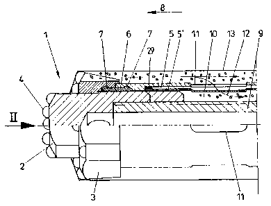
In Figs. 1 and 2, a drill bit is generally denoted by 1,
being comprised of a central portion, the socalled pilot bit
2, and an annular bit 3 surrounding the pilot bit 2. On the
forward end faces of the pilot bit 2 and of the annular bit
3 are provided conventional working tools known per se such
as, for instance, substantially semi-spherical hard material
insets 4 for working the material.
?0 On the end facing away from the working surfaces of the
drill bit 1, a jacket tube having a relatively small wall
thickness of, for instance, 2 mln is coupled with the drill
bit 1, wherein coupling is effected by means of a profiled
annular intermediate piece 6 engaging, via step- or nose-
?5 like projections 7, in corresponding recesses provided in
the regions both of the annular bit 3 and of the foremost
portion of the external jacket tube 5. An entrained inner
jacket tube 5' on its upper end region comprises a stop
element 29 tightly abutting or.~ the outer jacket tube 5.
30 Entrainment of the outer jacket. tube 5 in the drilling or
advancing direction indicated by arrow 8 is effected via the
coupling 6 by tensile action in the axial direction, while
the drill bit 1 is rotatably mounted relative to the jacket
tubes 5 and 5 ~ in a manner that this rotating movement will
35 not be impeded during drilling of the drill bit 1. It is,
thus, apparent that the jacket tubes 5 and 5 ~ , which may be
designed in an accordingly thin-walled manner, are entrained
by the drill bit 1, the jacket tubes 5 and 5' surrounding
CA 02271655 1999-OS-11
CA 02271655 2004-07-13
28664-11
- 13 -
the drill rod assembly schematically indicated by 9 while
forming a free space 10.
It is, furthermore, apparent from Fig. 1 that the jacket
S tube 5 and the jacket tube 5' in their foremost portions
comprise a plurality of peripherally distributed passage
openings 11 mutually overlapping in the telescoped state,
through which worked material can be introduced into the
free space between the drill rod assembly 9 and the tubes 5
and 5' according to arrow 12 and subsequently can be
conveyed outwards. The drill rod, assembly 9 may be designed
as a tube or provided with any other conduit via which a
gaseous or liquid flushing agent can be supplied and pressed
out into the free space 10 through the openings provided
between the drill bit 1 and the passage openings 11.
The external contour of the drill hole to be produced is
schematically indicated by 13 in Figs. 1 and 2. It is
immediately apparent that, when using accordingly thin-
?0 walled jacket tubes 5 and 5' which are merely exposed to
tensile action in the axial direction of the drill hole
caused by the drill bit 1 during the working procedure, the
diameter of the drill hole 13 may altogether be dimensioned
accordingly smaller. After completion of the drill hole 13,
the pilot bit 2, which preferably has a cross section
deviating from the circular form, is decoupled from the
annular bit 3 and drawn off through the jacket tube 5'
together with the drill rod assembly such that the entire
inner space defined by the jacket tube 5' will be left, for
instance, to the introduction of a roof bolt or a filling
mass.
The illustration according to Fig. 3 depicts a larger
longitudinal portion, it being apparent that the pilot bit
3~ or central part 2 of the drill bit has already been removed
together with the drill rod assembly so that only the jacket
tubes or lining tubes 5 and 5' as well as the annular bit 3
have been left in the drill hole 13: From Fig. 3 it is,
furthermore, apparent that a .coupling 6
CA 02271655 2004-07-13
28664-11
- 14 -
is coupled to the drill bit in the foremost portion
between the drill bit or remaining
annular bit 3 and the jacket tube 5. via the passages 11
provided in the foreward portion, a filling mass may, for
instance, be introduced into the frbnt region of the drill
hole 13 for an anchorage also intb the free space between
the delimitation of the drill hole 13 and the externally
located jacket tube 5. Further longitudinal portions of the
externally located jacket tubes 5 comprise projections 31
and 32 in their end portions, which projections are coupled
with a sleeve 30 firmly connecting two portions of internal-
ly located jacket tubes 5'.
Fig. 4 illustrates a configuration in which a roof bolt
schematically indicated by 15 is insertable, in particular
by screwing, after the drill rod assembly has been removed
into the jacket tubes 5 and 5' schematically illustrated in
the completely extended state, said roof bolt 15 being
additionally supported or braced on the soil by means 'of a
screw assembly 16 in its bare zone. In that case, a suitable
filling mass may have been additionally introduced into the
jacket tubes 5 and 5' directly with the insertion of the
roof bolt 15 in order to secure anchoring of the foremost
portion with the annular bit 3 having remained in the soil.
?5
In the representation according to Figs. 5 and 6, a modified
embodiment is shown in an illustration similar to Figs. 1
and 2, wherein a jacket tube again denoted by 5 is rotatably
fixed directly to the outer circumference of an annular bit
17 and a pilot bit equipped with cutting edges 18 is denoted
by 19. Fixation to the outer circumference of the annular
bit 17 in this embodiment is realized via appropriately
offset or stepped partial regions both on the annular bit 17
and on the end of the jacket tube 5 facing the drill bit 1,
the corresponding profiled sections being denoted by 20 and
21. The internally located jacket tube as well as its stop
element are again denoted by 5' and 29, respectively. The
drill rod assembly coupled with the drill bit 1 is denoted
by 22. Also in this embodiment, the central portion or pilot
CA 02271655 2004-07-13
28664-11
- 15 -
bit 19 of the drill bit 1 is pulled out together with the
drill rod assembly 22 through the interior of the jacket
tubes 5, 5' after completion of the'drill hole; whereupon a
roof bolt, for instance, may again be inserted and/or a
filling may additionally be provided with a solidifying
material and, in particular, grout.
Instead of inserting a roof bolt or anchor into a drill hole
13 lined with the jacket tubes 5 and 5', such a drill hole
13 may also serve, for instance, for drainage, wherein in
that case a plurality of perforations or apertures are to be
provided distributedly over the lengths of the jacket tubes
5 and 5' as well as peripherally.
In the embodiment represented in Fig. 7, an optionally
multi-part drill bit comprising hard material insets 4 is
again denoted by 1, j acket tubes entrained by the drill bit
1 being denoted by 5 and 5~. While the jacket tubes 5, 5~ in
the preceding embodiment may be made of, for instance, a
metallic material, the jacket tubes 5 and 5'
and the stop element 29 in the embodiment represented in
Fig. 7 are produced of synthetic material.
Fixation to the drill bit 1 is realized via a plurality of
?5 coupling elements in the form of balls 23, which are
received in corresponding recesses 24 of semi-circular cross
section provided on the rear side of the drill bit 1 and
complementary semi-circular recesses 25 of a connection
piece 26, the connection piece 26 being directly connected
with the jacket tube 5 of synthetic material. The balls 23,
which form the coupling elements between the drill bit 1 and
the jacket tube 5, thus constitute a coupling in the manner
of a ball bearing, thereby allowing for accordingly simple
rotation between the jacket tube 5 and the drill bit 1
during a rotary or rotary percussive movement. Since a
jacket tube 5 of synthetic material will exhibit an
accordingly high flexibility, there are additionally
provided in the region immediately following upon the drill
bit 1 so as to overlap the jacket tube 5, a supporting tube
- 16 -
27 on the inner side as well as a supporting tube 28 on the
outer side, between which the jacket tube 5 of synthetic
material is appropriately fastened or clamped immediately
consecutive to the connection piece 26, wherein said
additional supporting means 27 and 28 may be made, for
instance, of metal.
With a view to adapting the material properties of the balls
23, which may be made of metal or synthetic material, to the
bearing surfaces or bearing elements in the region of the
recesses 24 and 25, the connection piece 26 as well as the
extension of the drill bit 1 likewise may be made of metal
or synthetic material or provided with appropriate coatings.
Fig. 8 schematically illustrates the internally and
externally located jacket tubes 5' and 5, respectively, as
they may be displaced relative to each other or slidingly
pulled along each other during the advance of the drill bit
into the rock or earth material. Fig. 8a depicts the first
jacket tube portions 5 and 5' in the telescoped position,
i.e. in the position at the beginning of drilling, viewed in
the direction towards the drill bit 1. The externally
located jacket tube section 5 schematically comprises an
intermediate member 6 on its leading end, which intermediate
~5 member is intended to fix the outer jacket tube portion 5 to
the drill bit 1 not illustrated in Fig. 8, the advance
direction of the drill bit 1 being indicated by arrows 33 in
Fig. 8. On its end facing away from the drill bit, the outer
jacket tube 5 comprises a proje<aion 34, which is slidingly
mounted on the inner jacket tube 5'. In an analogous manner,
a projection 29 is provided on the end of the inner jacket
tube 5' facing the drill bi~~ 1, which projection may
interact with the projection 34 of the outer jacket tube 5
in the extended state.
In Fig. 8b, the first two jacket tube portions of both the
outer and inner jacket tubes 5 and 5' are schematically
indicated, wherein the first jacket tube portion 5, viewed
in the direction towards the drill bit 1, again comprises a
CA 02271655 1999-OS-11
CA 02271655 2004-07-13
28664-11
- 17 -
projection 34 on its end facing away from the drill bit 1,
which projection interacts with the projection 29 of the
inner jacket tube 5' in the extended state. The two outer
jacket tubes 5 illustrated are not directly interconnected,
but merely connected via a sleeve 3d firmly connecting the
two internally located jacket tubes ~'. For this connection,
projections 31, 32 are provided on the two outer jacket tube
portions 5 on the end regions facing each other, which
projections may engage in respective recesses of the sleeve
element 30. In the telescoped state, both the outer jacket
tube portions 5 and the inner jacket tube portions 5' are,
thus, firmly interconnected by the sleeve 30.
In order to have available as a lining for the drill hole
also the length of the inner jacket tube portion during
further advance into the rock or soil material, the
projection 31 is brought out of engagement with the
respective recess of the sleeve 30 by a rotary movement of
the second jacket tube portion 5, viewed from the direction
of the drill bit 1, relative to the sleeve 30 of the inner
jacket tube 5', as illustrated in Fig. 8C, whereupon the
outer jacket tube 5, by further advance of the drill bit 1
in the direction of arrow 31, is slidingly guided on the
inner jacket tube 5' until the stops 29 and 34 provided on
?5 the jacket tubes 5 and 5', respectively, abut each other.
In order that also the length of the first jacket tube
portion 5', viewed from the direction of the drill bit 1,
may be used for lining a drill hole, a tension opposite to
the direction of the advance movement is subsequently
induced on the end facing away from the drill bit 1 by
holding fast the outer jacket tube 5, thus causing the
projection 32 of the first outer jacket tube portion 5 to be
torn out of the respective recess of the sleeve 30 of the
inner jacket tube 5' and the jacket tube portion 5 of the
outer jacket tube, viewed in the direction towards the drill
bit 1, to be slidingly entrained on the first jacket tube
portion 5' in the direction towards the advance movement.
- 18 -
In the completely extended state, as represented in Fig. 8d,
the lining of the drill hole is thus designed to be
profiled, thereby being able to clearly reduce, in
particular, the frictional forces acting on the jacket
S tubes.
CA 02271655 1999-OS-11