Sélection de la langue

Search

Sommaire du brevet 2272528 

Énoncé de désistement de responsabilité concernant l'information provenant de tiers

Une partie des informations de ce site Web a été fournie par des sources externes. Le gouvernement du Canada n'assume aucune responsabilité concernant la précision, l'actualité ou la fiabilité des informations fournies par les sources externes. Les utilisateurs qui désirent employer cette information devraient consulter directement la source des informations. Le contenu fourni par les sources externes n'est pas assujetti aux exigences sur les langues officielles, la protection des renseignements personnels et l'accessibilité.

Disponibilité de l'Abrégé et des Revendications

L'apparition de différences dans le texte et l'image des Revendications et de l'Abrégé dépend du moment auquel le document est publié. Les textes des Revendications et de l'Abrégé sont affichés :

  • lorsque la demande peut être examinée par le public;
  • lorsque le brevet est émis (délivrance).
(12) Demande de brevet: (11) CA 2272528
(54) Titre français: CONNEXION OPTIQUE ET UNITE DE CONNEXION POUR ECHANGE DE DONNEES ENTRE PERIPHERIQUES
(54) Titre anglais: OPTICAL CONNECTION AND CONNECTION UNIT FOR THE EXCHANGE OF DATA BETWEEN DEVICES
Statut: Réputée abandonnée et au-delà du délai pour le rétablissement - en attente de la réponse à l’avis de communication rejetée
Données bibliographiques
(51) Classification internationale des brevets (CIB):
  • H04J 14/00 (2006.01)
(72) Inventeurs :
  • WEIS, BERND X. (Allemagne)
(73) Titulaires :
  • ALCATEL
(71) Demandeurs :
  • ALCATEL (France)
(74) Agent: ROBIC AGENCE PI S.E.C./ROBIC IP AGENCY LP
(74) Co-agent:
(45) Délivré:
(22) Date de dépôt: 1999-05-21
(41) Mise à la disponibilité du public: 1999-11-27
Licence disponible: S.O.
Cédé au domaine public: S.O.
(25) Langue des documents déposés: Anglais

Traité de coopération en matière de brevets (PCT): Non

(30) Données de priorité de la demande:
Numéro de la demande Pays / territoire Date
198 23 587.9 (Allemagne) 1998-05-27

Abrégés

Abrégé anglais


An optical connection and a connection unit between individual installation
units (2) is
proposed for the exchange of data between devices, in which the devices (1)
communicate
with one another by means of optical signals, and the optical signals overcome
at least the
distance between two adjacent installation units.

Revendications

Note : Les revendications sont présentées dans la langue officielle dans laquelle elles ont été soumises.


4.
Claims
1. Optical connection (4) for the exchange of data between devices (1) which
are
mounted in individual installation units (2) in an enclosed space, the devices
(1)
communicating with one another by means of optical signals from connection
units
(3), characterised in that the connection units (3) comprise at least one
transmitter (5)
and at least one receiver (6) connected to a multiplexer (11) and a
demultiplexer (10),
respectively.
2. Connection unit (3) for the exchange of optical signals in accordance with
Claim 1,
characterised in that the connection unit (3) has a calibration transmitter
(8) and a
calibration receiver (9).
3. Connection unit (3) for the exchange of optical signals in accordance with
Claim 2,
characterised in that the connection unit (3) is controlled by the system
control of the
devices (1) in an installation unit (2).
4. Connection unit (3) for the exchange of optical signals in accordance with
Claim 3,
characterised in that the connection unit (3) has its own monitoring unit (7).
5. Connection unit (3) for the exchange of optical signals in accordance with
Claim 4,
characterised in that the calibration of the strengths of the optical signals
is effected
automatically after evaluation of the calibration signal.
6. Connection unit (3) for the exchange of optical signals in accordance with
Claim 5,
characterised in that a time signal is transferred with the calibration
signal.
7. Connection unit for the exchange of optical signals in accordance with
Claim 1,
characterised in that it is gimbal-mounted in the installation unit (2), and
is adjusted
mechanically in accordance with the calibration signal.

Description

Note : Les descriptions sont présentées dans la langue officielle dans laquelle elles ont été soumises.

CA 02272528 1999-OS-21
1
Optical connection and connection unit for the exchange of data between
devices
The invention is based on an optical connection for the exchange of data
between devices and
a connection unit for the exchange of optical signals of the type described in
the independent
claims. A large number of individual devices and components are required for
the most
widely differing applications, which are fitted into installation units such
as racks. This large
number of components and devices must in general communicate with one another
and
exchange information and signals. An example of this is a digital switching
station, in which,
for example, up to 40 individual installation units may be located and must be
connected to
one another. For the installation of the different units it is of significance
which devices must
communicate with one another, depending on their individual tasks.
Accordingly, the
arrangement of the individual installation units within an area is a logistics
problem. The data
connections are, in this situation, created by the individual installation
units, the individual
racks, via optical fibre or wire connections. Positioning in relation to one
another is therefore
established in such a way that it is not possible simply to unplug and change
the individual
connections.
It is known in the state of the art, for example from US 5 091985, to connect
individual
devices with one another in a rack optically by means of a waveguide
structure. In this
situation, it is assumed that high data rates can be transferred very flexibly
by optical
communications. The individual components of a rack in this situation comprise
a
transmitter-receiver structure, which creates the image of the information on
a waveguide by
means of an optical imaging device, so that all the devices connected to this
waveguide can
receive the information from the waveguide. This structure serves to provide
communication
within a rack.
The optical connection in accordance with the invention for the exchange of
data between
devices, which are installed in separate installation units in a closed space,
has in contrast the
advantage that the devices in the installation units communicate with one
another by means of
optical signals, where the optical signals overcome the distance between the
installation units.
As a result, a wireless connection is achieved between individual racks, which
can be erected
in the area as an island solution, and offers free access to optical
connections with one
another. For such an optical connection, light is advantageously transferred
between
installation units, so that it is only necessary to ensure that there is no
interruption of the light
path and hence of the information flow.
The connection unit in accordance with the invention, for the exchange of
optical signals, has
the advantage that it consists of at least one transmitter and at least one
receiver, which are
3 0 connected to a demultiplexer and a multiplexer. As a result, a large
number of channels for
the transfer of data are advantageously opened, so that the requirement for
high data rates and
for different data channels are fulfilled.
The quality of the transfer is advantageously monitored by a special
calibration transmitter
and a calibration receiver. As a result, the system can be automatically
monitored and a data
transfer free of complications can be assured. The synchronisation of the
signals is
advantageously ensured by means of a separate system clock, the signals of
which are
transmitted and received with the calibration signal and matched to one
another. The
adjustment of the connection units to one another is effected during
installation of the units, in

CA 02272528 1999-OS-21
2
that the transmitter and receiver units are mechanically tuned to one another.
To do this, the
connection units are gimbal-mounted in the installation units, and can be
pushed against one
another and adjusted in a simple manner. The automatic monitoring for this
calibration signal
allows for an indication as to whether any readjustment should be undertaken.
One embodiment of the invention is shown in the drawings and explained in
greater detail in
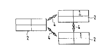
the following description. Figure 1 shows a schematic representation of the
installation units,
Figure 2 an optical connection between two installation units and Figure 3 a
connection unit.
Figure 1 shows the installation units 2 seen from above, in which individual
devices 1 are
installed. The installation units may be designed in the form of racks. The
installation units
can be located in any desired position in an area, in which situation their
position is
determined by their tasks and the possible connections. The installation units
2 communicate
with one another by means of an optical connection 4.
Figure 2 shows the optical connection 4 between two installation units 2.
Located on the
installation units 2 are connection units 3, by means of which the optical
connection 4 is
established. The optical connection 4 can, as shown in this embodiment, be
provided with a
mechanical protection device 14. The mechanical protection device 14 serves to
ensure that
the optical path is not interrupted by any objects or persons and that the
data communications
are not thereby interrupted.
Figure 3 shows a connection unit 3, such as is used to establish
communications between the
installation units. The connection unit 3 features several transmitters 5,
which are connected
via an input 13 and a multiplexes 11 with the devices in the installation
unit. On the reception
2 0 side, the connection unit 3 features a receiver 6, which delivers the
information via a
demultiplexer 10, across the output line 12, to the devices in the
installation unit. In addition,
the connection unit 3 also features a calibration transmitter 8 and a
calibration receiver 9. A
monitor unit 7, which is in connection both with the multiplexes 11 as well as
with the
demultiplexer 10, monitors the connection unit. To create the connection
between the
installation units, the data from the units is processed in the multiplexes
and issued to the
transmitter bank. The arrangement of the transmitters and their number
corresponds to the
requirements of the data transfer. Used in this context, for example, are
infra-red diodes, with
infra-red sensors provided on the reception side. As a calibration
transmitter, an infra-red
diode can likewise be used: The calibration receiver has a considerable
surface area, so that it
is possible to assess the position of the calibration signal being issued by
the other connection
unit. In this way it is possible to ensure that the receivers of the
connection unit, with smaller
surface areas, will be adequately reached by the light signal. Depending on
the protocol
which is being used to send and receive the data from the installation units,
it is necessary to
3 0 establish a common time base for the different installation units. This
time base can be
created in a simple manner by modulating the calibration signal. The optical
connection
system in accordance with the invention makes it possible to instal new
installation units and
new devices in a highly flexible manner and connect them by optical paths.
This allows a
high degree of flexibility to be achieved in the design, for example, of a
switching station.
Optical communications are, however, also a simple way of doing away with
elaborate and
unwieldy cabling arrangements in other applications. The actuation of the
connection units is
possible in a simple manner and in general requires no greater expenditure
than the
communications between the devices already requires. Only in.the.situation in
which larger
volumes of data are to be transferred is the integration of a multiplexes and
demultiplexer a

CA 02272528 1999-OS-21
3
requirement, in order to provide the individual transmitters of the
transmitter bank and the
individual receivers of the receiver bank with data, or to assess their data.

Dessin représentatif
Une figure unique qui représente un dessin illustrant l'invention.
États administratifs

2024-08-01 : Dans le cadre de la transition vers les Brevets de nouvelle génération (BNG), la base de données sur les brevets canadiens (BDBC) contient désormais un Historique d'événement plus détaillé, qui reproduit le Journal des événements de notre nouvelle solution interne.

Veuillez noter que les événements débutant par « Inactive : » se réfèrent à des événements qui ne sont plus utilisés dans notre nouvelle solution interne.

Pour une meilleure compréhension de l'état de la demande ou brevet qui figure sur cette page, la rubrique Mise en garde , et les descriptions de Brevet , Historique d'événement , Taxes périodiques et Historique des paiements devraient être consultées.

Historique d'événement

Description Date
Inactive : CIB expirée 2013-01-01
Inactive : CIB de MCD 2006-03-12
Demande non rétablie avant l'échéance 2003-05-21
Le délai pour l'annulation est expiré 2003-05-21
Réputée abandonnée - omission de répondre à un avis sur les taxes pour le maintien en état 2002-05-21
Demande publiée (accessible au public) 1999-11-27
Inactive : Page couverture publiée 1999-11-26
Inactive : CIB en 1re position 1999-07-20
Demande reçue - nationale ordinaire 1999-06-21
Exigences de dépôt - jugé conforme 1999-06-21
Lettre envoyée 1999-06-21
Inactive : Certificat de dépôt - Sans RE (Anglais) 1999-06-21

Historique d'abandonnement

Date d'abandonnement Raison Date de rétablissement
2002-05-21

Taxes périodiques

Le dernier paiement a été reçu le 2001-04-27

Avis : Si le paiement en totalité n'a pas été reçu au plus tard à la date indiquée, une taxe supplémentaire peut être imposée, soit une des taxes suivantes :

  • taxe de rétablissement ;
  • taxe pour paiement en souffrance ; ou
  • taxe additionnelle pour le renversement d'une péremption réputée.

Les taxes sur les brevets sont ajustées au 1er janvier de chaque année. Les montants ci-dessus sont les montants actuels s'ils sont reçus au plus tard le 31 décembre de l'année en cours.
Veuillez vous référer à la page web des taxes sur les brevets de l'OPIC pour voir tous les montants actuels des taxes.

Historique des taxes

Type de taxes Anniversaire Échéance Date payée
Taxe pour le dépôt - générale 1999-05-21
Enregistrement d'un document 1999-05-21
TM (demande, 2e anniv.) - générale 02 2001-05-21 2001-04-27
Titulaires au dossier

Les titulaires actuels et antérieures au dossier sont affichés en ordre alphabétique.

Titulaires actuels au dossier
ALCATEL
Titulaires antérieures au dossier
BERND X. WEIS
Les propriétaires antérieurs qui ne figurent pas dans la liste des « Propriétaires au dossier » apparaîtront dans d'autres documents au dossier.
Documents

Pour visionner les fichiers sélectionnés, entrer le code reCAPTCHA :


Pour visualiser une image, cliquer sur un lien dans la colonne description du document. Pour télécharger l'image (les images), cliquer l'une ou plusieurs cases à cocher dans la première colonne et ensuite cliquer sur le bouton "Télécharger sélection en format PDF (archive Zip)" ou le bouton "Télécharger sélection (en un fichier PDF fusionné)".

Liste des documents de brevet publiés et non publiés sur la BDBC .

Si vous avez des difficultés à accéder au contenu, veuillez communiquer avec le Centre de services à la clientèle au 1-866-997-1936, ou envoyer un courriel au Centre de service à la clientèle de l'OPIC.


Description du
Document 
Date
(aaaa-mm-jj) 
Nombre de pages   Taille de l'image (Ko) 
Dessin représentatif 1999-11-09 1 3
Abrégé 1999-05-20 1 10
Description 1999-05-20 3 178
Revendications 1999-05-20 1 40
Dessins 1999-05-20 1 9
Courtoisie - Certificat d'enregistrement (document(s) connexe(s)) 1999-06-20 1 116
Certificat de dépôt (anglais) 1999-06-20 1 165
Rappel de taxe de maintien due 2001-01-22 1 112
Courtoisie - Lettre d'abandon (taxe de maintien en état) 2002-06-17 1 183