Sélection de la langue

Search

Sommaire du brevet 2273109 

Énoncé de désistement de responsabilité concernant l'information provenant de tiers

Une partie des informations de ce site Web a été fournie par des sources externes. Le gouvernement du Canada n'assume aucune responsabilité concernant la précision, l'actualité ou la fiabilité des informations fournies par les sources externes. Les utilisateurs qui désirent employer cette information devraient consulter directement la source des informations. Le contenu fourni par les sources externes n'est pas assujetti aux exigences sur les langues officielles, la protection des renseignements personnels et l'accessibilité.

Disponibilité de l'Abrégé et des Revendications

L'apparition de différences dans le texte et l'image des Revendications et de l'Abrégé dépend du moment auquel le document est publié. Les textes des Revendications et de l'Abrégé sont affichés :

  • lorsque la demande peut être examinée par le public;
  • lorsque le brevet est émis (délivrance).
(12) Demande de brevet: (11) CA 2273109
(54) Titre français: TIDY GUIDE
(54) Titre anglais: TIDY GUIDE
Statut: Réputée abandonnée et au-delà du délai pour le rétablissement - en attente de la réponse à l’avis de communication rejetée
Données bibliographiques
Abrégés

Abrégé anglais


The coiling, storage, moving and uncoiling of electrical cords,
ropes cables, hoses, (generic cord) is fraught with difficulty in
terms of tangling and lengthy time spent on unravelling before
usage. In this invention a tool entitled "Tidy Guide" has been
devised that attaches to the cord and enables the user to coil,
transport, store, secure and unravel the cord tangle free. The
device enables each coil to be placed on the previous coil single
file within a guide. The guide looks like a tuning fork. A snap
ring secures the coil at the open end of the guide.
The apparatus attaches to the cord by way of a longitudinal slot
extending from the bottom of the guide upwards. A slotted cap
screws on to the bottom and a notch in the cap forces the cord
against the inside wall of the slot thus forming a friction fit.
The cord threads through to the inside base of the fork. For
electrical cords the device is best located near the mail plug of
the cord. For other cords the location can vary.
The tool as illustrated is for after market application and it is
conceivable that the tool could neatly be fused or otherwise
incorporated on to an electrical or other cord at time of
manufacturing.
The tool could be designed for different lengths diameters and
types of cord. As well the construction of the device could well
be a metal such as aluminium, reinforced plastics i.e. PVC,
urethane, nylon, fibreglass and in :some cases wood. The device
could be cast or crafted with appropriate rigid tubing.

Revendications

Note : Les revendications sont présentées dans la langue officielle dans laquelle elles ont été soumises.


CLAIMS:
The embodiments of the invention in which exclusive property or
privilege is claimed are defined as follows:
1. A manually operable tool which is affixed to and enables the
normal coiling of extension cords, air hoses rope, cable or
other coilable materials within a guide shaped as a tuning
fork and which enables single file stacking of gathered coils.
2. A tool as described in claim 1 which is affixed and encircles
the cord with a friction cap mechanism or other means
including incorporation or otherwise fusing onto the cord by
and in the manufacture of the cord.
3. A tool as defined in claim 1 and 2, in which a snap ring in
the form of a steel split rim is threaded through a slot at
the distal end of one of the forks of the guide.
4. A tool as defined in claim 1, 2 and, 3 in which a snap ring can
be activated by slipping upward in the slot over the end of
the two forks of the guide to contain the coils in the guide.
5. A tool as defined in claim 1, 2, 3, and 4, in which a snap
ring when activated is held in place by the force of the
gathered coils in the guide which forces the forks of the
guide outward and ensures a tight fit.
6. A tool as defined in claim 1, 2, 3, 4, and 5, in which the
snap ring can be deactivated and all or some of the coils can
be removed from the guide singly or jointly.
7. A tool as defined in claim 1, 2, 3, 4, 5, and 6, where the
snap ring can be deactivated and some of the contained coils
removed for use with remaining coils being contained within
the guide by reactivating the snap ring.
8. A tool as defined in claim 1, 2, 3, 4, 5, 6, and 7, where the
snap ring is holstered in the rectangular slot when
deactivated.
9. A tool as defined in claim 1, 2, 3, 4, 5, 6, 7, and 8 which
can be adapted to stationary use by deactivating the snap ring
and hanging on a hook.
10. A tool as defined in claim 1, 2, 3, 4, 5, 6, 7, 8, and 9 in
which all components save the snap ring can be cast of
aluminium, plastics and or crafted of similar type rigid
tubing materials.
11. A tool as defined in claim 1, 2, 3, 4, 5, 6, 7, 8, 9, and 10
which can be sized to accommodate different types and lengths
of cords.

Description

Note : Les descriptions sont présentées dans la langue officielle dans laquelle elles ont été soumises.

CA 02273109 1999-OS-25
SPECIFICATIONS:
1. This device is designed to complement the normal manual
movement entailed in coiling up cords. Similarly the
secured coils can be unravelled as we normally do but without
tangling.
2. Existing devices for managing cords entail bulky reels that
are quite heavy and cumbersome. Other spooling devices seem
awkward and poorly attached and dangle when in use. Tie
downs attached to the cord which enable the user to tie up
the accumulated coils would not appear to prevent the
tangling when unravelling. Similarly the common practice of
coiling the cord in the hand and tying a knot with the cord
on completion always has a tendency to tangle when unravelled
particularly if the cord has been moved or thrown about in
coiled position.
3. The device I have designed is light, simple, sturdy,
streamlined, easily attached i~o the cord and enables the
simple placement of coils in single file within the guide.
Once the cord is fully placed in the guide it can be secured
by a snap ring at the top of tree guide. This ring slips over
the top end of the two forks of the guide and is held secure
in part by the force of the strands of cord within the guide
which have a tendency to force the two forks apart. The
intact cord can then be stored, transported, thrown around,
kicked and physically manipulated without unravelling. When
ready to unravel simply release: the snap ring and uncoil the
cord strand by strand or pull out several strands and throw
out to the intended place of use. If full length is not
needed secure with snap ring and guide will hold existing
contained cord intact. The guide stays attached to the cord
and does not adversely impede the safety or utility of the
cord. The great benefit of the device is that it is easy to
attach to after market cords, it complements our natural
motion of gathering up cords, is easy to use, is versatile,
streamlined, durable, portable, weighs only ounces and is
adaptable to many situations.
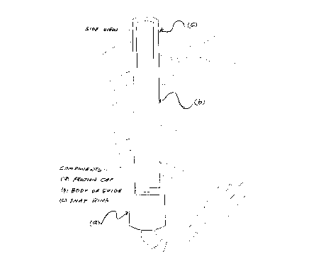
4. In drawings which illustrate embodiments of the invention
Figure 1 is an elevation of one embodiment. Figure 2 is a
top view of the embodiment. A simple electrical cord is
shown for illustration. Figures 7, 8, 9, 10, illustrate 4
different side views of the device. Figure 7 is the same
view as Figure 1. Figures 3, 4, 5, 6 show the top views
while Figures 11, 12, 13, 14 show respective bottom views of
the body of the guide. Figure 17 shows the concave view of
the friction cap, Figure 18 a side view and Figure 19 the
convex bottom view of the cap.

CA 02273109 1999-OS-25
The tool comprises a guide as illustrated in Figure 1. Figure
8 and 10 illustrate the tuning fork appearance of the guide
which enables the single file placement of strands of cord.
The snap ring in Figure 1 is i:n the closed position thereby
containing the cord within the guide. Also Figure 1 shows
the attachment of the friction cap which screws onto the
bottom of the guide and squeezes the cord to the inside wall
of the base of the guide thereby forming a friction fit. The
tool is thus held securely at one spot on the cord.
Figure 15 illustrates a top view of the snap ring and Figure
16 the side view. The attachment of the ring to the
body of the tool is shown in Figures 20, through to 23.
Figure 20 and 21 show the ring :in the inactive position while
Figures 22 and 23 show the ring in the closed position. To
activate the ring, it is slid upwards and pushed over the
opposite fork. The force of the coils in the guide tend to
push the forks outward slightly and ensures a tight fit.
The drawings are full scale however the sizes can be modified
to adapt to different cord lengths, thickness and type. The
example tool illustrated can accommodate a 15 meter medium
heavy duty extension cord. A longer guide would be required
for cords longer than the 15 meters. Similarly the materials
can range from metal such as aluminium to various plastics.
The device can with the exception of the snap ring be cast as
two pieces or crafted from available rigid tubing and capping
devices
5. The device can also be used :in stationary mode simply by
releasing the snap ring and hanging it over a nail or hook.
This would be of utility in a workshop situation when dealing
with a long or heavy cord or 'where the full length was not
required. The single file coiling keeps the cords neat and
tidy. A stationary device lends itself to managing
compressed air hoses, in shops or gas stations. Also some
types of water hoses. For permanent stationary applications
a second point of attachment of the tool to enable stationary
wall positioning would be beneficial and could easily be
incorporated in the design. The various applications would
require different sizing and type of materials depending on
strength required. Permanent stationary devices could be
constructed of heavier materials.
In portable mode the device could find application in
specialised endeavours such a:~ mountain rescue where long
sections of rope have to be managed or generally in any
situation where long lengths of cords, hoses or flexible
coilable materials are used.

CA 02273109 1999-OS-25
The device could also be fused or designed to be
permanently affixed to an elecarical extension cord at the
time of manufacture. This would preclude the need for the
after market attachment feature of the device. An
attractive guide could be incorporated as part of the
extension cord.

Dessin représentatif
Une figure unique qui représente un dessin illustrant l'invention.
États administratifs

2024-08-01 : Dans le cadre de la transition vers les Brevets de nouvelle génération (BNG), la base de données sur les brevets canadiens (BDBC) contient désormais un Historique d'événement plus détaillé, qui reproduit le Journal des événements de notre nouvelle solution interne.

Veuillez noter que les événements débutant par « Inactive : » se réfèrent à des événements qui ne sont plus utilisés dans notre nouvelle solution interne.

Pour une meilleure compréhension de l'état de la demande ou brevet qui figure sur cette page, la rubrique Mise en garde , et les descriptions de Brevet , Historique d'événement , Taxes périodiques et Historique des paiements devraient être consultées.

Historique d'événement

Description Date
Inactive : CIB de MCD 2006-03-12
Demande non rétablie avant l'échéance 2002-05-27
Le délai pour l'annulation est expiré 2002-05-27
Inactive : Lettre officielle 2001-07-06
Réputée abandonnée - omission de répondre à un avis sur les taxes pour le maintien en état 2001-05-25
Demande publiée (accessible au public) 2000-11-25
Inactive : Page couverture publiée 2000-11-24
Inactive : CIB attribuée 1999-07-14
Inactive : CIB en 1re position 1999-07-14
Exigences de dépôt - jugé conforme 1999-06-30
Inactive : Lettre officielle 1999-06-30
Inactive : Certificat de dépôt - Sans RE (Anglais) 1999-06-30
Demande reçue - nationale ordinaire 1999-06-29

Historique d'abandonnement

Date d'abandonnement Raison Date de rétablissement
2001-05-25

Historique des taxes

Type de taxes Anniversaire Échéance Date payée
Taxe pour le dépôt - petite 1999-05-25
Titulaires au dossier

Les titulaires actuels et antérieures au dossier sont affichés en ordre alphabétique.

Titulaires actuels au dossier
RICHARD A. NICKEL
Titulaires antérieures au dossier
S.O.
Les propriétaires antérieurs qui ne figurent pas dans la liste des « Propriétaires au dossier » apparaîtront dans d'autres documents au dossier.
Documents

Pour visionner les fichiers sélectionnés, entrer le code reCAPTCHA :


Pour visualiser une image, cliquer sur un lien dans la colonne description du document. Pour télécharger l'image (les images), cliquer l'une ou plusieurs cases à cocher dans la première colonne et ensuite cliquer sur le bouton "Télécharger sélection en format PDF (archive Zip)" ou le bouton "Télécharger sélection (en un fichier PDF fusionné)".

Liste des documents de brevet publiés et non publiés sur la BDBC .

Si vous avez des difficultés à accéder au contenu, veuillez communiquer avec le Centre de services à la clientèle au 1-866-997-1936, ou envoyer un courriel au Centre de service à la clientèle de l'OPIC.


Description du
Document 
Date
(aaaa-mm-jj) 
Nombre de pages   Taille de l'image (Ko) 
Abrégé 1999-05-25 1 42
Description 1999-05-25 3 144
Revendications 1999-05-25 1 55
Dessins 1999-05-25 4 66
Page couverture 2000-11-21 1 43
Dessin représentatif 2000-11-21 1 6
Certificat de dépôt (anglais) 1999-06-30 1 165
Avis de rappel: Taxes de maintien 2001-02-27 1 120
Courtoisie - Lettre d'abandon (taxe de maintien en état) 2001-06-26 1 182
Deuxième avis de rappel: taxes de maintien 2001-11-27 1 120
Avis de rappel: Taxes de maintien 2002-02-26 1 121
Taxes 2001-06-18 2 89
Correspondance 1999-06-30 1 17