Note : Les descriptions sont présentées dans la langue officielle dans laquelle elles ont été soumises.
CA 02275705 1999-06-18
WO 98/27358 PCT/AU97/00857
- 1 -
10
FRICTION DINING ATTACHMENTS
Technical Field
This invention relates to the attachment of
friction linings to backing plates, as may be utilised in
vehicle or other machine braking systems, clutch
mechanisms, or other mechanisms where friction linings are
to be attached to a backing plate, disc or brake shoe.
For the purposes of this specification reference
Will be made mainly to the attachment of friction lining
material to sole plates of brake shoes for vehicles.
particularly heavy duty vehicles such as buses, trucks, and
trailers, which because of their weight and the terrain in
which they may be required to operate, must have secure
attachment of the friction linings on the brake shoes to
avoid brake malfunction and the consequences resulting
therefrom. The invention is also applicable to other
vehicles such as cars, motorcycles, trains, off-road
equipment, earth moving equipment, elevators, and aeroplane
braking systems, and clutch mechanisms where applicable, as
well as other machinery where brake or clutch mechanisms
may be necessary.
sUgST~TU'tE S~E~T (RULE 26)
CA 02275705 1999-06-18
WO 98/27358 PCT/AU97/00857
- 2 -
Background Art
Conventional attachments between friction linings
and backing plates, such as between brake linings and sole
plates in brake shoes, have involved the use of rivets
coupling the linings to the backing plates. The heads of
the rivets on the lining side of the attachment are
received in recessed holes, and maintain attachment until
such time as the friction linings wear away to an extent
that the rivet heads and an associated braking surface,
such as a surface of a brake drum or brake disc, become
sufficiently close as to require replacement of the
friction linings. One well known problem with such
attachments is that there is a build up of grit in the
recesses for the rivets which as a result of the rubbing
action of the linings against the associated braking
surface causes scouring or other damage to the braking
surface requiring machining maintenance from time to time
to repair the damage to the brake drum or disc. In
addition, in order to securely attach the linings to the
backing plates (sole plates) specialised equipment is
frequently required and a considerable number of rivets may
be reguired which adds to the expense, both in parts and
labour, in manufacturing and maintaining the brake, clutch
or equivalent component.
An alternative attachment is also known using
direct bonding of the linings to the backing plates without
the necessity for rivets and using hot or cold bonding
agents which because of the advances in bonding agent
technology have allowed for reliable attachment in most
instances. However, in some severe heavy duty
applications, such as braking systems for trucks, trailers,
and more particularly buses where safety factors-are
particularly critical, there are perceived problems in
relation to detachment of the friction linings (brake
linings) from the backing plates (brake soles) and although
brake failures resulting from such detachments are very
SUBSTITUTE SHEET (RULE Zfiy
CA 02275705 1999-06-18
WO 98/27358 PCT/AU97/00857
- 3 -
rare, there is some concern on the part of truck and bus
operators to utilising bonded brake linings in some severe
service applications. The likely main cause of brake
malfunction with bonding techniques is that as a brake
lining becomes worn, and as a result thinner, heat
generated during extreme braking operations is more rapidly
conducted to the interface between the lining and the
backing plate whereby the hot or cold bonding agent can be
adversely affected to the extent that its bonding action
breaks down and the lining separates from the backing
plate.
In the past it has been proposed to provide as
attachment between a friction lining and a backing plate,
in which the lining is clamped to the backing plate by one
or more clamping elements attached to the backing plate and
cooperating with one or more associated grooves in the
lining in such a manner as to prevent the lining from being
detached from the backing plate.
One such attachment is disclosed in Australian
patent specification no. 149358 entitled "Improvements in
or Relating to~a Clutch or Brake Mechanism" and relating to
a patent granted to Hans Rangvald Amundsen (hereinafter
referred to as the Amundsen Patent). However, such
proposals have involved the use of keying elements which
extend completely across the backing plate, as do the
associated grooves in the lining, thus leading to the
possibility that the lining may move laterally of, or even
off, the backing plate under certain circumstances.
It is therefore an object of the present
invention to provide an attachment between a friction
lining and backing plate which eliminates, or at least
minimises, the above problems with known riveted, bonded,
or keyed and groove attachments, and in particular with
regard to the latter any possibility that there will be
SUBSTITUTE SHEET (RULE 26)
CA 02275705 1999-06-18
PCT/AU97/00857
Received 12 November 1998
- 4 -
relative lateral movement to any large extent between the
lining and the backing plate.
Disclosure of the Invention
In accordance with the present invention there is
provided an attachment between a friction lining material
and a backing plate, in which the lining is attached to the
backing plate by a plurality of keying elements attached to
the backing plate and cooperating with a plurality of
associated recesses in the lining in such a manner as to
prevent the lining from becoming detached from the backing
plate, said recesses being formed in the face_of the lining
abutting said backing plate and terminating-short of the
other face of the lining, wherein the wall of at least one
recess completely surrounds and is engaged by its
associated keying element and/or at least two recesses
extend from opposite edges of the lining and partially
across the lining with the inner ends of the recesses
forming abutments against which their associated keying
elements engage, and whereby in either case there will be
no, or a limited amount of, relative movement between the
lining and the backing plate in any direction.
Preferably some of the peripheral edges of the
keying element are designed so as to be of a wedge shape
and the edges of their associated recesses are
correspondingly shaped, whereby, a greater cross-sectional
area of contact is created resulting in superior lining
retention compared with conventional fastening methods, and
also due to a difference in co-efficients of expansion
betweer~i~'the material of the keying element and the material
of the friction lining, the higher the temperature under
which the attachment is operating the greater the degree of
grip between the keying element and the friction lining,
and the tighter the friction lining is drawn against the
backing plate.
AMENDED SHEET - IPEA/AU
CA 02275705 1999-06-18
PCT/AU97/0085 7
Received 12 November 1998
- 4a -
In one embodiment at least some of the keying
elements are elongate and received in correspondingly
elongate grooves and at least one of those keying elements
and its associated groove extends only partially across the
interface between the backing plate and friction lining
from one side thereof and opening through that side, and at
AMENDED SHEET - IPEA/AU
CA 02275705 1999-06-18
WO 98/27358 PCT/AU97/00857
- 5 -
least one other of those keying elements and associated
groove also extends only partially across the interface
from the other side thereof and opening through that side.
In another embodiment at least one of the keying
elements is a suitable shaped element received in a recess
residing totally within the friction lining material.
Preferably the keying elements are attached to
the backing plate by screws, bolts or rivets extending
through apertures in the backing plates and into the keying
elements after the lining has been positioned on the
backing plate.
In a still further alternative embodiment the
attachment may be formed by a combination of screws, bolts
or rivets and bonding or gluing.
In a still further alternative embodiment the
keying elements may be moulded into the lining material at
the time of moulding of the linings.
Possibly a bonding agent may also be provided
between the lining and the backing plate to enhance the
attachment of the lining to the plate.
The invention envisages the combination of a
friction lining having at least one recess and a keying
element for association therewith as defined above.
Brief Description of the Drawings
Two preferred embodiments of the invention, and
several variations thereof, will now be described with
reference to the accompanying drawings, in which;
SUHSTiTtJ'I'E SHE~'f (RULE 26)
CA 02275705 1999-06-18
WO 98127358 PCT/AU97100857
- 6 -
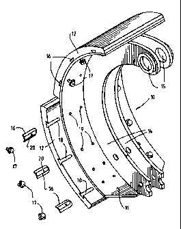
Figure 1 is a partially exploded perspective view
from beneath of a typical brake shoe incorporating the
first embodiment of the present invention.
Figure 2 is a plan view from above of a keying
element used in the preferred embodiment of Figure 1.
Figure 3 is an end elevational view of the keying
element of Figure 2,
Figure 4 is a perspective view from above of the
keying element of Figure 2,
Figure 5 is a perspective view from below of the
keying element of Figure 2,
Figure 6 is a cross-sectional view through a
keying element for use in a second embodiment of the
invention,
Figure 7 is a plan view of the keying element of
Figure 6, and
Figure 8 is a cross-sectional view of a lining
having the keying elements of Figures 6 and 7 received in
recesses in the lining.
Best Modes for Carrying Out the Invention
These preferred embodiments of the invention
relate to a brake shoe for a vehicle, which shoe is of
arcuate configuration to cooperate with the internal
braking surface of a cylindrical brake drum.
In the first preferred embodiment the brake shoe,
designated as 10, comprises an arcuately shaped elongate
brake sole 11 to which are applied, in this case a pair of,
arcuately shaped brake lining segments 12. The radially
SUBST1'TLJTE SNE~T {RULE Z6)
CA 02275705 1999-06-18
WO 98/27358 PCT/AU97100857
_ 7 _
inaer side of the brake shoe 11 carries a pair of shoe webs
14 extending along the length and beyond the ends of the
brake sole, and spaced apart in parallel relationship, and
also having apertures 15 therethrough at either end for
attachment to brake actuating mechanisms as is conventional
with vehicle braking systems. To this point the typical
brake shoe described is of a conventional type, and to
which in past, the brake lining segments are either riveted
or bonded to the brake sole as discussed previously.
In accordance with this first preferred
embodiment of the invention, the use of a plurality of
rivets to directly attach respective brake lining segments
12 to the brake shoe, are dispensed with, and instead
elongate keying elements 16 stamped, pressed, roll formed
or otherwise formed from flat metal plate. In this example
six such elements are provided for each lining segment
(three on each lateral side thereof), and are fastened
using a single self tapping screw 17 for each keying
element, unlike the Amundsen Patent where two bolts are
required. Also, unlike the Amundsen Patent, the keying
elements only extend partially across the width of the
brake sole and cooperate in a keying action with associated
grooves 18 formed corresponding partially across the
25- internal side of the respective lining segments. In this
preferred embodiment, the keying elements 16 are of wedge
shaped configuration tapering inwardly towards the brake
sole 11 and the grooves 18 are matingly shaped to in effect
prevent detachment of the lining segments from the brake
sole. The lining segments fitted with keying elements are
placed in position on the brake sole, whereafter the self
tapping screws 17 are inserted through apertures 19 in the
brake sole 11 and into threaded engagement with
corresponding holes 20 in the keying elements, which may be
punched or otherwise formed for receiving appropriate self
tapping screws. Alternatively the holes~20 may be threaded
holes formed in solid keying elements and the self tapping
SUBSTITUTE SHEET (RULE 26)
CA 02275705 1999-06-18
WO 98/27358 PC"T/AU97I00857
- g -
screws replaced by bolts. In this preferred embodiment as
referred to above the keying elements are wedge shaped that
is their periphery 16a are inclined, typically at an angle
of 45°, and the peripheries of their associated recesses
are correspondingly inclined, the effect of which is that a
greater cross-sectional area of contact is created
resulting in superior lining retention compared with
conventional fastening methods, and also, due to the
differences in co-efficients of expansion between the metal
of the keying element and the material of the brake lining
segments, the higher the temperature under which the brake
system is operating the greater the degree of grip between
the keying elements and lining segments becomes and the
tighter the lining segments are drawn against the brake
shoe. Such an effect is not possible with the T-shaped
keying elements of the Amundsen Patent, whilst in addition
the relatively thin flanges defining the T-shaped grooves
within the lining of the Amundsen Patent are likely to
break under pressure. Also for the purposes of this
preferred embodiment the brake sole 11 may be a
conventional brake sole having two laterally spaced
apertures 19 which Would normally receive rivets in
accordance with normal practice, but we have found when
testing existing brake systems utilising the present
invention only one fastening screw 17 is required and thus
the additional aperture is not required. In the case of
brake soles specifically manufactured for the purposes of
the present invention the additional aperture 19 will not
be required.
Calculations have shown that the area of the
cooperating surfaces between the keying elements 16 and the
grooves 18 will be significantly higher than that provided
by the normal number of rivets used to attach lining
segments in conventional lining attachments. The optimum
number of keying elements and the means for fastening them,
such as the self tapping screws 17 or bolts, will be
SUBSTITUTE SHEET (RULE 26)
CA 02275705 1999-06-18
WO 98/27358 PCT/AU97100857
_ g _
ultimately determined by the application, physical
characteristics of the friction lining and the shear
strength of the fastening means.
The present invention resists lateral movement of
the lining elements as it involves the use of grooves
formed only partially across the internal side of the
respective lining segments from one side and the other, and
the keying elements are inserted from both sides, whereby,
apart from preventing movement of the lining elements along
the length of the brake sole, the lining segments will also
be prevented from moving laterally of the brake sole.
In addition, the attachment between the lining
segments 12 and the brake sole may be enhanced by providing
a bonding agent (either hot or cold bonding) between the
interface between the lining segments and the brake sole.
Tn this embodiment of the invention, the ends of
the keying elements 16 are formed as semi-circular shapes
to match the semi-circular internal ends of the associated
grooves 18 which would result from a wedge shaped circular
milling tool being one of the most convenient ways of
forming the wedge shaped grooves 18. Alternatively the
inner ends of the keying elements and associated groove may
be merely squared as with their outer ends. In the case of
solid keying elements, they be forged from, for example
high tensile brass, whilst in a still further alternative
embodiment of the invention the majority of the length of
the keying elements may be cut from a length of a more
conveniently formed extrusion to form elongate rectangular
keying elements and if the semi-circular ends thereof are
required these could be provided by separately formed
moulded plastic parts.
SUBSTZTtJTE SHEET tRULE 26)
CA 02275705 1999-06-18
WO 98/27358 PCT/AU97/00857
- 10 -
The length of the keying elements 16 and
associated grooves 18 extending laterally from either side
of the brake shoe may vary on either side of the brake shoe
and be such that one on one side may overlap the adjacent
one on the other side, thus enhancing the resistance
against separation of the lining along the length of the
brake sole.
Referring to Figures 6, 7 and 8 of the drawings,
in a second preferred embodiment of the invention the
keying elements are circular button shaped keys 21 punched
from suitable metal section such as steel or metal alloys,
for example brass, using a punch which will form the button
into a concave shape as shown in Figure 6. The degree of
25 concavity may be varied depending on the particular
application.
The buttons 21 are thereafter inserted into
recesses 22 provided in the lining material 23 and of
inwardly and outwardly tapering configuration as shown in
Figure 8, with the buttons being pressed flat within the
recesses whereby, because of their original concavity, its
innermost side is caused to flare or splay outwardly to
allow firm wedging of the buttons within the recesses. The
buttons 21 may be formed with a splined or knurled edge or
circumference to increase their grip on the friction
material within the recesses.
The diameter and thickness of the buttons may
vary depending on the particular application, as may the
metals from which they are formed, whilst apart from punch
forming, the buttons may be machined or moulded to the
required shape.
Either before or after the buttons are
pressed
into the recesses, they may have holes drilled, punched or
otherwise formed therein to receive self-tapping screws
SU85TITUTE SKEET (RULE 26)
CA 02275705 1999-06-18
WO 98/27358 PCT/AU97/00857
- lI -
(not shown) to attach them to a brake sole via a hole
through the brake sole. The attachment may alternatively
be achieved by drilled and threaded holes to receive bolts
or resistant welded studs or special pop or cherry type
rivets. The holes may be formed during punching, machining
or moulding of the button.
The buttons or keying elements may be of other
shapes, such as square, rectangular, hexagonal or other
polygonal shapes and may be suitable knurled, splined or
otherwise formed to increase their grip on the friction
material.
As an alternative to interference fitting or
wedging of the buttons in their respective recesses they
may be bonded or glued into position, or a combination of
both screws, bolts or rivets and bonding or gluing. In a
still further alternative the buttons may be moulded into
the material of the friction lining when the lining is
moulded.
The buttons or keying elements of any of the
above embodiments may be formed from steel, metal alloys,
plastics or other suitable composites.
SUBSTITUTE SHEET (RUL~ 2fi~