Note : Les descriptions sont présentées dans la langue officielle dans laquelle elles ont été soumises.
CA 02275790 1999-06-21
,.
1
AIR RETURN BULKHEAD FOR REFRIGERATION TRAILERS
This application is a continuation-in-part of application serial number
08/801,214 which is a continuation-in-part of application serial number
08/701,215, now abandoned.
BACKGROUND OF THE INVENTION
A refrigeration bulkhead is a passive device mounted on the inside front
wall of a refrigeration trailer. It generally covers the width of the front
wall and
has a height either halfway up or fully covering the front wall, thereby
covering all
or part of a refrigeration unit generally mounted at the upper center portion
of the
wall. The bulkhead serves two functions. First, it creates a space between the
trailer load and the trailer front wall. This space is used to facilitate air
movement
from the floor of the trailer up the front wall to the refrigeration unit.
Through its
air intake, the refrigeration unit can remove heat from the air and exhaust
the heat
to the outside of the trailer. Second, the bulkhead protects the refrigeration
unit
from fork lifts or other loading devices and their loads.
BRIEF DESCRIPTION OF THE PRIOR ART
Refrigeration trailer bulkheads are well known. The earliest bulkhead was
a wooden pallet arranged on end to protect the refrigeration unit while still
providing air flow. The temporary pallet was then replaced with a more
permanent
and aesthetically pleasing lattice work assembly of aluminum uprights and
crossmembers. While these prior bulkheads afforded protection to the
refrigeration
unit, they did not provide directional air flow throughout the trailer
resulting in
short cycling, i.e., uneven temperature distribution within the trailer. __
CA 02275790 1999-06-21
2
As the need for directional airflow within the trailer was recognized, solid
bulkheads replaced lattice work structures. Essentially, the cross members of
the
lattice were replaced by solid sheets of plywood, fiberglass reinforced
plywood, or
thin gauge aluminum. The bulkhead extended between the sides of the trailer
and
was sealed at the top, with the bottom being left open for a return air
intake.
Most recently, molded polyethylene bulkheads have been introduced as
solid bulkheads. These are strong enough to resist impact and include several
vertically arranged ribs which direct air through the space between the
bulkhead
and the trailer front wall. At the bottom of each rib is a small triangular
shaped
opening for air intake. Other air intake holes are located on the side of the
vertical
ribs. While the prior molded bulkheads are inexpensive, easy to install in a
variety
of trailers, and stackable, they do not fully overcome the short cycling
problem
referenced above because they do not provide adequate directional and cross-
directional return air flow to the refrigeration unit. Furthermore, they do
not
accommodate expansion and contraction due to fluctuating temperatures.
SUMMARY OF THE INVENTION
Accordingly, it is a primary object of the invention to provide an air return
bulkhead adapted for mounting adjacent a refrigeration unit in spaced relation
from
a front vertical wall of a refrigeration trailer. The bulkhead includes a
rectangular
panel molded from synthetic plastic material and including a front wall and
side,
top, and bottom walls extending normal to the front wall to define a cavity.
The
front wall includes a plurality of horizontally spaced tapered sections in the
lower
portion thereof which define a plurality of pallet stops co-planar with the
front
wall. The tapered sections each contain a plurality of openings which enable
air to
enter the cavity from the bottom of the trailer. First and second baffles
extend into
CA 02275790 1999-06-21
3
the cavity from the rear of the front wall. The first baffles are arranged
above the
tapered sections and the second baffles are on opposite sides of the rear
upper
portion of the front wall. The baffles reinforce the panel and cooperate to
direct air
upwardly and toward the center of the cavity where the refrigeration unit is
arranged.
According to another object of the invention, the bulkhead includes a
plurality of bypass vents arranged above the tapered sections to enable air to
enter
the cavity when the openings in the tapered sections are blocked.
It is a more specific object of the invention to provide a plurality of
integral
flanges extending from the top, bottom and side walls generally parallel to
the front
wall. The flanges can be trimmed in order to fit the panel within trailers of
different dimensions. An improved strapping mechanism for removably fastening
the bulkhead to the trailer wall is also provided.
It is yet another object of the invention to provide a pair of vertically
extending spaced wings connected with the top wall of the bulkhead to fit
against
side portions of the refrigeration unit to deliver air from the cavity to
openings in
the side portions of the refrigeration unit.
BRIEF DESCRIPTION OF THE FIGURES
Other objects and advantages of the invention will become apparent from a
study of the following specification when viewed in the light of the
accompanying
drawing, in which:
Fig. 1 is a cutaway perspective view of a refrigeration trailer illustrating
the
optimum air flow therethrough;
CA 02275790 1999-06-21
. ._
4
Fig. 2 and 3 are perspective views, respectively, of refrigeration trailer
bulkheads according to the prior art;
Figs. 4 and S are front plan and perspective views, respectively, of the air
return bulkhead according to the invention;
Fig. 6,7, and 8 are sectional views taken along lines 6-6, 7-7, and 8-8,
respectively of Fig. 4;
Fig. 9 is a front plan view of a preferred embodiment of the air return
bulkhead of the invention;
Fig. 10 is a rear perspective view of the bulkhead of Fig. 9;
Fig. 11 is a front plan view of the panel flanges illustrating the fastening
assembly therefor;
Fig. 12 and 13 are front and top plan views, respectively, of a washer used
for the fastening assembly of Fig. 11;
Fig. 14 is a perspective view of an air return bulkhead including vents in the
sides thereof;
. Fig. 15 is a detailed perspective view of the strap mechanism for removably
connecting the air return bulkhead to the front wall of a trailer; , __
CA 02275790 1999-06-21
S
Fig. 16 is a front plan view of an air return bulkhead including vertically
extending wings according to the invention; and
Figs 17 and 18 are perspective views, respectively, of the wings of Fig. 16.
DETAILED DESCRIPTION
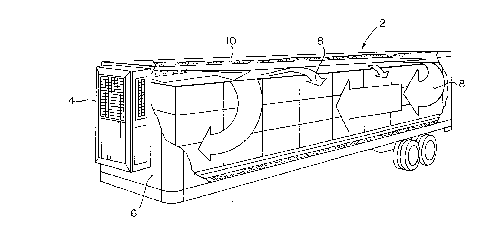
The field of the invention will first be described with reference to Fig. 1
wherein a refrigeration trailer 2 is shown. These trailers are used to
transport
numerous refrigerated products including ice cream, produce, meat, computers,
and dry goods. Accordingly, they include a refrigeration unit 4 which is
mounted
on the front wall 6 of the trailer toward the top and center thereof. The
refrigeration unit cools air within the trailer, exhausts heat to the exterior
of the
trailer, and distributes the cooled air into and through the trailer. As shown
by the
arrows 8, internal return air ideally is drawn into the refrigeration unit at
the
bottom front of the trailer and distributed adjacent the top wall 10 of the
trailer
toward the rear. The cool air falls to the floor at the rear and along the
sides of the
trailer where it is drawn back to the refrigeration unit.
In order to protect the refrigeration unit from the load and from forklifts
used to load the trailer and to afford air flow to the refrigeration unit,
bulkheads
were developed for the front wall of the trailer. In Fig. 2, there is shown a
lattice
work bulkhead comprising vertical aluminum z-bars 12 and aluminum cross bars
14. In addition to being labor intensive to install, lattice type bulkheads do
not
provide directional return air flow to the refrigeration unit within the
trailer
resulting in short cycling and hot and cold spots within the trailer rather
than a
desirable uniform temperature. __
CA 02275790 1999-06-21
6
In order to improve air flow, a solid bulkhead was developed as shown in
Fig. 3. This bulkhead retained the vertical aluminum columns 12 but replaced
the
cross members with sheets of plywood 16 which in some instances included
fiberglass for reinforcement. An apertured screen 18 is arranged along the
bottom
of the bulkhead and serves as an air inlet. Pallet stops 20 at the bottom of
the
columns 12 are provided to prevent damage to the bulkhead and the
refrigeration
unit. Although an improvement over the lattice type bulkheads, the solid
fiberglass
reinforced plywood bulkhead of Fig. 3 is expensive and heavy making it
difficult to
install and requiring custom fitting for each size trailer.
Turning now to Figs. 4-8, the air return bulkhead according to the
invention will be described. The bulkhead is essentially a unitary panel 22
which is
molded from synthetic plastic material into a generally rectangular
configuration.
As well be developed below, the panel can be formed with a standard width and
height and then trimmed to fit refrigeration units of dif~'erent
configurations.
1 S Preferably, the width of the panel is such that the panel extends
generally across the
width of the trailer front wall. The height of the panel is at least half the
height of
the front wall and preferably selected so that the panel extends over at least
the air
return of the refi-igeration unit. The panel is adapted for mounting within
the trailer
adjacent to but spaced from the front wall to define an air return space
between the
panel and the trailer wall. No support members are required.
The panel 22 includes a front wall 24, a top wall 26, a bottom wall 28, and
side wahs 30. The top, bottom, and side walls extend in a direction normal to
the
planar front wall to define a cavity for air flow. Along the bottom, the panel
front
wall includes a plurality of spaced tapered sections 32. As shown in Fig. 6,
the
taper extends downwardly and rearwardly at an angle « relative to the plane
containing the front wall. The angle « is on the order of 30°. Each
tapered
CA 02275790 1999-06-21
7
section contains a plurality of openings 34 which allow air to be drawn into
the
cavity. The openings are preferably arranged in rows and columns, with the
same
number of openings being provided in each section so that air is drawn into
the
cavity uniformly from across the bottom of the panel. The tapered sections
containing the openings further act as a filter to prevent debris from
entering the
cavity.
Between the tapered sections 32 the remaining portions of the front wall
define bumpers or pallet stops 36 against which a pallet bearing a load can be
placed within the trailer.
A plurality of first baffles 38 are integrally molded within the panel front
wall 24. More particularly, the baffles extend into the cavity from the rear
surface
of the front wall. Each baffle has a sinusoidal configuration as shown in Fig.
7 to
define recesses 40 through which air may pass. As shown in Fig. 4, the first
baffles
are arranged in two sets on opposite sides of the panel. Each of the baffles
extends
upwardly toward the vertical centerline at an angle (3 relative to horizontal.
The
angle (3 is preferably 60°.
A pair of second curved baffles 42 are provided adjacent the upper portions
of the side walls 30. The second baffles are also integrally molded with the
panel
and extend from the rear surface thereof with a sinusoidal configuration to
define a
plurality of recesses 44.
The first baffles 38 direct air from the openings 34 upwardly and toward
the center of the panel where the refi-igeration unit is located. The second
baffles
42 direct air laterally toward the upper central portion of the panel. Thus,
the
baffles cooperate to circulate air toward the refrigeration unit. The recesses
in the
baffles afford cross-ventilation and equalize the pressure and air flow within
the
cavity. These two features improve air movement and result in increased
efficiency
CA 02275790 1999-06-21
8
of the refrigeration unit which receives air from the bulkhead and exhausts
warm
air to the outside of the trailer and cooled air to the interior of the
trailer adjacent
the top wall as shown in Fig. 1. Moreover, the sinusoidal configuration of the
baffles reinforce the panel since the portions between the recesses can abut
against
the front wall of the trailer.
The top 26, bottom 28, and side 30 walls of the panel each include a flange
46 extending therefrom in a direction parallel to the front wall. The flange
can be
trimmed to adapt the panel to differently sized trailers, so that once
installed, such
as by screwing the panel to the walls of the trailer, a sealed bulkhead is
provided,
but for the openings 34 along the bottom thereof.
A preferred embodiment of the invention is illustrated in Figs. 9 and 10. As
is evident from these figures, the rectangular panel 122 is similar to that of
the
embodiment of Figs. 4-6 and includes a front wall 124, a top wall 126, a
bottom
wall 128, and side walls 130 which define an air flow cavity. The front wall
includes spaced tapered sections 132 containing openings 134 and defining
pallet
stops 136. A flange 146 extends from the top, bottom, and side walls.
The primary difference in the embodiment of Figs. 9 and 10 from that of
Figs. 4-6 is in the configuration of the first baffles 138 and the second
baffles 142.
As best shown in Fig. 9, the lower portion of the baffles 13 8 are aligned
with the
pallet stops 136. This arrangement improves the air flow of the bulkhead since
air
entering the cavity via the openings 134 in the tapered sections 132 passes
upwardly and between the baffles 138. The outermost baffles 138a are truncated
to allow a space between these baffles and the side walls 130. The second
baffles
142 extend parallel to the vertical centerline CL of the panel. The first and
second
baffles 138 and 142 contain at least one recess 144 as shown in Fig. 10 to-
allow the
passage of air therethrough.
CA 02275790 1999-06-21
9
The bulkhead of Figs. 9 and 10 also includes a truncated third baffle 148
co-linear with the vertical centerline CL which is also aligned with a central
pallet
stop 136. Where the upper portions of the first baffles on opposite sides of
the
centerline intersect, the first baffles have a portion 150 of reduced
dimension as
shown in Fig. 10. This enables air to flow through the intersecting baffles at
the
center of the bulkhead.
Another difference in the bulkhead of Figs. 9 and 10 is the provision of a rib
152 extending laterally across the front panel 124 between the upper edges of
the
pallet stops 136 and the lower portions of the first and third baffles 138,
148. The
rib, which may also be provided in the bulkhead of Figs. 4-6, increases the
rigidity
and strength of the bulkhead.
One drawback to screwing the panels to the trailer wall is that the panels
buckle or separate from the wall owing to expansion or contraction of the
plastic
material in response to temperature fluctuations. This deformation of the
panels
destroys the seal around the perimeter of the panel, whereby air flow behind
the
bulkhead is no longer controlled in the proper fashion.
In order to overcome this problem, an improved fastening system for the
bulkhead is provided which allows for limited movement of the bulkhead
relative to
the trailer wall. Referring to Fig. 11, the flange 146 extending from the top,
bottom, and side walls contains a plurality of slots 154 in the outer edge
thereof. A
washer 156 is arranged within and above each slot and is adapted to receive a
self
tapping screw or rivet 158. Referring to Figs. 12 and 13, the washer 156
includes
an oblong upper portion 156a and a depending shoulder portion 156b through
which a rivet-receiving opening 160 passes. The shoulder portion 156b of the
washer has a depth greater than the thickness of the flange and an outer
diameter
less than the width of slow 154. The top oblong portion 156a has a long
CA 02275790 1999-06-21
dimension greater than the width of the slot. Because of the unique
configuration
of the washer, the bulkhead panel 122 is af~'orded a limited degree of
movement
relative to the wall to which it is fastened to accommodate expansion and
contraction thereof.
5 An alternative fastening system is shown in Figs. 14 and 1 S. The panel 222
contains a pair of spaced horizontal channels 248, 250 which extend
continuously
across the panel front wall 224 between the side walls 230. The lower channel
248
is arranged between the tapered sections 232 and the first baffles 238. The
upper
channel 250 is arranged below the second baffles 242. The channels 248, 250
are
10 adapted to receive adjustable straps 252 as shown in Fig. 15. The straps
pass
through loops 254 secured to the front vertical wall of the trailer. A
cinching
device 256 at one end of each strap (or on the associated loop) is provided
for
tightening and releasing the straps.
With the alternative fastening system of Figs. 14 and 15, the bulkhead is
quickly and easily mounted on the trailer wall by passing the straps through
the
loops and channels and then tightening the straps to securely hold the
bulkhead in
place. In order to remove the bulkhead, the straps are released and the
bulkhead
falls away from the trailer wall.
Under certain conditions, the air openings 234 in the bottom portion of the
panel front panel 224 become blocked, impeding air flow through the bulkhead
to
the refrigeration unit. For example, the trailer may be improperly loaded with
cargo placed against the air intake area, thereby blocking the openings. Also,
over
time debris such as paper and plastic sheeting from the trailer or trailer
cargo is
drawn into the openings and clogs the same.
When the air openings at the bottom of the bulkhead are clogged,-the
temperature distribution throughout the trailer becomes uneven which could
CA 02275790 1999-06-21
11
damage or spoil the cargo. Accordingly, bypass vents 258 are provided in the
upper portions of the side walls 230 as shown in Fig. 14. The vents are
normally
closed during operation of the refrigeration unit. However, when the air
openings
234 are blocked, the pressure in the cavity behind the bulkhead drops below
the
ambient pressure within the trailer causing the vents to open and allow return
air
from the trailer to enter the cavity. In the preferred configuration, the
vents are
integrally formed in the side walls by cutting through the side walls to
define a flap
which can be deflected into the cavity in response to a pressure drop in the
cavity.
Alternatively, separate venting members can be formed and attached to the side
walls, with openings being cut in the side walls beneath the venting members.
Turning now to Figs. 16-18, another feature of the air return bulkhead 222
according to the invention will be described. In most refrigeration units 204,
the
air return intake is at the bottom of the unit and the bulkhead can be fit up
to the
bottom of the unit to funnel the return air to the unit's air intake. However,
some
refrigeration units such as the THERMO-KING SUPER II have air intakes 205 on
the side which are not normally covered by the bulkhead. In order to
accommodate such units, the air return bulkhead of the invention can be
provided
with spaced vertically extending wings 260 connected with the top wall 226 of
the
bulkhead panel. Each wing is hollow and contains a portion 262 in the rear
thereof
which is cut away prior to fitting adjacent to the air intakes 205 of the
refrigeration
unit 204. The use of the wings 260 achieves two objectives for optimal air
flow.
First, the bulkhead can be mounted as low as possible in the trailer to take
air from
the trailer floor. Second, the additional air intakes of the refrigeration
unit are
covered. If the wings are not used, the only way to achieve these objectives
is to
make the bulkhead taller which greatly increases its cost.
CA 02275790 1999-06-21
12
The wings 260 are preferably formed of synthetic plastic material. At
installation, the bulkhead is fastened to the trailer wall adjacent the lower
edge of
the refrigeration unit, with the top wall of the bulkhead panel being cut away
adjacent the unit to allow air from the bulkhead cavity to enter the unit. The
wings
are trimmed according to the configuration of the unit and then mounted on the
bulkhead, snugged up against the refrigeration unit, and fastened to the
trailer wall.
Only air from the cavity is drawn into the side air intakes 205 of the
refrigeration
unit via the wings.
While in accordance with the provisions of the patent statute the preferred
forms and embodiments of the invention have been illustrated and described, it
will
be apparent to those of ordinary skill in the art that various changes and
modifications may be made without deviating from the inventive concepts set
forth
above.