Sélection de la langue

Search

Sommaire du brevet 2276084 

Énoncé de désistement de responsabilité concernant l'information provenant de tiers

Une partie des informations de ce site Web a été fournie par des sources externes. Le gouvernement du Canada n'assume aucune responsabilité concernant la précision, l'actualité ou la fiabilité des informations fournies par les sources externes. Les utilisateurs qui désirent employer cette information devraient consulter directement la source des informations. Le contenu fourni par les sources externes n'est pas assujetti aux exigences sur les langues officielles, la protection des renseignements personnels et l'accessibilité.

Disponibilité de l'Abrégé et des Revendications

L'apparition de différences dans le texte et l'image des Revendications et de l'Abrégé dépend du moment auquel le document est publié. Les textes des Revendications et de l'Abrégé sont affichés :

  • lorsque la demande peut être examinée par le public;
  • lorsque le brevet est émis (délivrance).
(12) Demande de brevet: (11) CA 2276084
(54) Titre français: NOEUD COULANT POUR SAUVETAGE MARITIME
(54) Titre anglais: MARINE RESCUE SNARE
Statut: Réputée abandonnée et au-delà du délai pour le rétablissement - en attente de la réponse à l’avis de communication rejetée
Données bibliographiques
(51) Classification internationale des brevets (CIB):
  • B63C 9/26 (2006.01)
  • A62B 1/16 (2006.01)
(72) Inventeurs :
  • KELLETT, K. CRAIGE (Canada)
(73) Titulaires :
  • K. CRAIGE KELLETT
(71) Demandeurs :
  • K. CRAIGE KELLETT (Canada)
(74) Agent: SMART & BIGGAR LP
(74) Co-agent:
(45) Délivré:
(22) Date de dépôt: 1999-06-23
(41) Mise à la disponibilité du public: 1999-12-25
Requête d'examen: 2000-04-05
Licence disponible: S.O.
Cédé au domaine public: S.O.
(25) Langue des documents déposés: Anglais

Traité de coopération en matière de brevets (PCT): Non

(30) Données de priorité de la demande:
Numéro de la demande Pays / territoire Date
2,241,512 (Canada) 1998-06-25

Abrégés

Abrégé anglais


A floatable marine rescue snare is provided
comprising one or more buoyant elongate rods axially
connected by a tie line and formed in a loop, with
slippage means fixed to one end of the snare and slidably
engaged with a portion of the snare between its two ends.
The tie line connects to a rescue rope by which it may be
thrown to a victim. Once looped around the upper torso
of the victim, the snare can be tightened by pulling on
the rescue rope to secure a rescue link while the buoyant
body of the snare maintains the victim afloat.

Revendications

Note : Les revendications sont présentées dans la langue officielle dans laquelle elles ont été soumises.


-7-
CLAIMS:
1. A marine rescue snare, comprising:
at least one flexible, buoyant elongate member
having an axial channel therethrough with a first
end and a second end;
a flexible tensile member extending through said
axial channel from said first to said second end
thereof;
means for connecting said flexible tensile member at
said first end to a rescue rope; and
slippage means connected to said flexible tensile
member at said second end for maintaining said
snare, in use, in the form of a loop accommodating
the upper torso of a person to be rescued, while
permitting relative movement of first and second
ends of the snare away from or toward each other for
respectively contracting or expanding said loop.
2. A marine rescue snare according to claim 1, wherein
a hollow elastomeric tube is seated in close fit along
the length of said channel, said flexible tensile member
extending through the interior of said tube.
3. A marine rescue snare according to claim 2, wherein
said slippage means comprises a ring of plastic roller
beads looped about said flexible buoyant elongate member
between said first and second ends.
4. A marine rescue snare according to claim 3, wherein
said tensile member is a rope having a polypropylene core
and an outer polyester sheath, a portion of said tensile
member extending from said first end of said axial

-8-
channel being securely formed into a tie loop for
connection of a rescue rope thereto.
5. A marine rescue snare according to claim 3, further
comprising end stop means for enlarging the diameter of a
portion of said elongate member near the first end
thereof to limit the motion of said second end of the
snare in expanding said loop.
6. A marine rescue snare according to claim 5, wherein
said end stop means is manually adjustable along said
buoyant elongate member for manual cinching of the loop
of the snare about the torso of a person.
7. A marine rescue snare according to claim 1, wherein
said flexible tensile member is a length of semi-rigid,
non-resilient cable joining two flexible, buoyant
elongate members and wherein an exposed portion of said
cable serves as a track for movement therealong of said
slipping means.
8. A marine rescue snare according to claim 7, wherein
said semi-rigid, non-resilient cable is a coaxial cable
having a steel core, an aluminum sheath and a filling of
lightweight plastic material.
9. A marine rescue snare according to claim 8, wherein
said slippage means comprises a rigid metal ring fixedly
attached to said cable at said second end of the axial
channel through said flexible, buoyant elongate members.

Description

Note : Les descriptions sont présentées dans la langue officielle dans laquelle elles ont été soumises.

CA 02276084 1999-06-23
- 1 -
BACKGROUND OF THE INVENTION
The present invention relates to apparatus and
methods for marine rescue, particularly in man overboard
situations.
The difficulties involved in throwing out a buoyant
life ring ("life preserver") to a victim in distress in
the water is well known. A number of devices have been
contrived which are floatable weighted objects of a shape
easier to throw than the simple annular life ring.
However, any devices which contemplate that the victim
effectively grasp a floatable member and/or lifeline in
order to be pulled to safety is subject to the limitation
that the victim may be in a state of panic or shock
rendering it difficult for him or her to maintain a grasp
upon the device.
Retrieval/rescue devices of a different character
have been devised which are in the nature of snares that
can be tightened round the torso of a victim, e.g., U.S.
Patents 4,599,074 (Beckly) and 4,596,530 (McGlinn).
These typically include a rigid boom and a flexible strap
capable of forming a loop for wrapping around the victim.
Upon pulling, the loop tightens around the victim for
effecting a rescue. Such snare devices are not buoyant,
nor meant to be thrown out freely to the vicinity of the
victim. Rather, the snaring mechanism is affixed to the
end of a boom or other rigid member which is extended to
the person in the water.
SUMMARY OF THE INVENTION
It is an object of the present invention to provide
a marine rescue snare which is buoyant and simple in
construction.

CA 02276084 1999-06-23
- 2 -
With a view to achieving this and other objects of
the invention, there is provided a floatable marine
rescue snare with a first and second end, which comprises
one or more flexible, buoyant elongate members such as
polyethylene flotation foam rods. A flexible tensile
member turns through an axial channel of the buoyant
member(s). In use, the snare is formed into a loop, with
slippage means fixed to one end of the snare and slidably
engaged with a portion of the snare between its two ends.
The snare can be attached to a rescue rope and
thrown to the victim. Once the loop of the snare is
around his or her upper torso, the snare is simply
tightened up by pulling on the rescue rope attached to
the first end of the snare, to secure a rescue link with
the victim and keep him or her buoyant.
BRIEF DESCRIPTION OF THE DRAWINGS
The invention will be further described, by way of
example only, with reference to the accompanying
drawings, in which:
Figure la is a diagrammatic representation of a
marine rescue flotation snare according to the present
invention;
Figure lb is a cross-sectional view, showing the
interior of the flexible, buoyant elongate member of the
device of Figure la;
Figures 2 and 3 are diagrammatic external views of
variants of the embodiment of Figures la and lb, the
interior construction being no different from that
embodiment;

CA 02276084 1999-06-23
- 3 -
Figure 4a is a diagrammatic representation of a
marine rescue snare according to a preferred embodiment
of the invention;
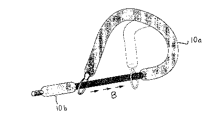
Figure 4b is a sectional view of the embodiment of
Figure 4a including an exploded fragmentary view to show
the construction of the co-axial cable used in this
embodiment;
Figure 5 illustrates the rescue of an overboard
victim using a marine rescue flotation snare according to
the present invention, thrown from a boat; and
Figure 6 illustrates the vertical lifting by a
rescue helicopter of a victim whose upper torso is
secured by a rescue snare of the kind shown in the
previous Figures.
DETAILED DESCRIPTION
Figure la/lb, Figure 2 and Figure 3 show variants of
an embodiment of an invention in which a central channel
runs axially along the centre of a flexible, buoyant rod
10. Closely fitted within the central channel is a
length of polyethylene or like elastomeric tubing 12
running from one end to the other. Along the interior of
the polyethylene tube there is threaded a strong and
flexible tensile member 14. This may be made of any of a
number of materials of the kind suitable for use as
rescue ropes. In a preferred embodiment, the tensile
member is a rope fabricated of a polypropylene core with
an outer polyester sheath.
In the variant of Figures la and b, at a first end
of the snare, tensile member 11 is secured in a tie loop
14a for a rescue rope (not shown), and at the other end
to slippage or roller means 16 which hold the snare in
the desired loop but allow for the loop to be enlarged or

CA 02276084 1999-06-23
- 4 -
contracted. The illustrated example of slippage/roller
means comprises a ring of polyethylene beads which run on
a looped end of tensile member 14. The bead-ring slider
16 may be prevented from coming right off the end of the
snare when it is opened to its maximum position by a
fixed, rigid stopping member 18 at the first, rescue rope
end of the snare.
A variation on the embodiment of Figures la and lb
is shown in Figure 2, where the tensile member extending
from the stopped end of the snare is first looped into
tie loop 14a and thence extends into a tag line 14c with
a handle 20.
In a further modification illustrated in Figure 3, a
rigid stopping member 18' is not longitudinally fixed
relative to flexible, buoyant rod 10, but with a selected
degree of frictional engagement can be manually pulled
along rod 10 against slippage/roller means 16 to cinch
the loop tighter around the chest of the wearer, as
desired. The adjustable snare retainer 18' is prevented
from sliding off rod 10 at the rescue rope end by a fixed
abutment 22, such as a washer secured to the end of the
snare.
Referring to Figure 5, after the snare is thrown out
to victim 12 and the victim 23 has put his or her arms
through the expanded loop of the device, pulling the
rescue line 24 in the direction illustrated generally by
arrow A will effect cinching of the snare around the body
of the victim by virtue of the free-sliding end 16.
As shown in Figure 6, this snaring action is also
advantageous in "vertical work" as when the victim must
be lifted out of the water by a rescue helicopter 25.
For this purpose, the rescue device may optionally be
provided with a cradle strap 26 attached by a separate
line 26a to the tow-rope end of rescue snare 10.

CA 02276084 1999-06-23
- 5 -
Figures 4a and 4b illustrate a currently preferred
embodiment of the snare according to the present
invention, in which the snare is formed of two sections
of flexible buoyant rod, l0a and lOb, connected through
central channels by a flexible tensile member 15 which is
constructed as a semi-rigid buoyant cable.
Such a cable is the subject of the present
applicant's U.S. Patent No. 5,370,434. The
distinguishing property of this cable is that it is
essentially semi-rigid, by which it is meant that the
cable is flexible while at the same time substantially
non-resilient, so that it will retain the shape into
which it is flexed.
The coaxial structure of cable is from the inside
out comprises a fibreglass centre core 15a, surrounded by
polyethylene foam 15b, and aluminum sheath 15a and, as
the outermost layer of the cable a polyethylene sheet
15d. Optionally in this embodiment, the flexible tensile
member 15 may be enwrapped by a hollow polyester webbing
material 17. The cable may be provided at both ends with
an aluminum hex fitting for connection to the slippage
means and external towing means.
The portion 19 of the cable which extends between
the polyethylene foam covered sections serves as the
loosening-tightening track along which sliding member 21
is free to move in the direction of arrows B toward the
extreme tightest configuration illustrated in dotted
outline, or in the reverse, loosening direction.
Just as with the embodiment of Figures 1 to 3, the
snare of the Figure 4 has the ability to be attached to a
rescue rope and thrown to a victim. Once around the
victim the snare can be tightened up to secure a rescue
link with the victim and to keep him or her afloat. I
have found that the particular embodiment of Figures 4a

CA 02276084 1999-06-23
- 6 -
and 4b is less bulky than the others and for that reason
more convenient to store and easy to throw out to a
victim in use.
It will be appreciated that, although specific
embodiments of the invention have been described herein
for purposes of illustration, various modifications may
be made without departing from the inventive concept.
Accordingly, the invention is not limited except by the
claims appended hereto.

Dessin représentatif
Une figure unique qui représente un dessin illustrant l'invention.
États administratifs

2024-08-01 : Dans le cadre de la transition vers les Brevets de nouvelle génération (BNG), la base de données sur les brevets canadiens (BDBC) contient désormais un Historique d'événement plus détaillé, qui reproduit le Journal des événements de notre nouvelle solution interne.

Veuillez noter que les événements débutant par « Inactive : » se réfèrent à des événements qui ne sont plus utilisés dans notre nouvelle solution interne.

Pour une meilleure compréhension de l'état de la demande ou brevet qui figure sur cette page, la rubrique Mise en garde , et les descriptions de Brevet , Historique d'événement , Taxes périodiques et Historique des paiements devraient être consultées.

Historique d'événement

Description Date
Inactive : CIB de MCD 2006-03-12
Demande non rétablie avant l'échéance 2004-10-12
Inactive : Morte - Taxe finale impayée 2004-10-12
Réputée abandonnée - omission de répondre à un avis sur les taxes pour le maintien en état 2004-06-23
Réputée abandonnée - les conditions pour l'octroi - jugée non conforme 2003-10-10
Un avis d'acceptation est envoyé 2003-04-10
Lettre envoyée 2003-04-10
Un avis d'acceptation est envoyé 2003-04-10
Inactive : Approuvée aux fins d'acceptation (AFA) 2003-03-31
Modification reçue - modification volontaire 2000-05-15
Lettre envoyée 2000-04-27
Exigences pour une requête d'examen - jugée conforme 2000-04-05
Toutes les exigences pour l'examen - jugée conforme 2000-04-05
Requête d'examen reçue 2000-04-05
Demande publiée (accessible au public) 1999-12-25
Inactive : Page couverture publiée 1999-12-24
Inactive : CIB en 1re position 1999-08-19
Inactive : Certificat de dépôt - Sans RE (Anglais) 1999-08-05
Exigences de dépôt - jugé conforme 1999-08-05
Demande reçue - nationale ordinaire 1999-08-03

Historique d'abandonnement

Date d'abandonnement Raison Date de rétablissement
2004-06-23
2003-10-10

Taxes périodiques

Le dernier paiement a été reçu le 2003-05-22

Avis : Si le paiement en totalité n'a pas été reçu au plus tard à la date indiquée, une taxe supplémentaire peut être imposée, soit une des taxes suivantes :

  • taxe de rétablissement ;
  • taxe pour paiement en souffrance ; ou
  • taxe additionnelle pour le renversement d'une péremption réputée.

Veuillez vous référer à la page web des taxes sur les brevets de l'OPIC pour voir tous les montants actuels des taxes.

Historique des taxes

Type de taxes Anniversaire Échéance Date payée
Taxe pour le dépôt - petite 1999-06-23
Requête d'examen - petite 2000-04-05
TM (demande, 2e anniv.) - petite 02 2001-06-26 2001-06-26
TM (demande, 3e anniv.) - petite 03 2002-06-24 2002-05-15
TM (demande, 4e anniv.) - petite 04 2003-06-23 2003-05-22
Titulaires au dossier

Les titulaires actuels et antérieures au dossier sont affichés en ordre alphabétique.

Titulaires actuels au dossier
K. CRAIGE KELLETT
Titulaires antérieures au dossier
S.O.
Les propriétaires antérieurs qui ne figurent pas dans la liste des « Propriétaires au dossier » apparaîtront dans d'autres documents au dossier.
Documents

Pour visionner les fichiers sélectionnés, entrer le code reCAPTCHA :


Pour visualiser une image, cliquer sur un lien dans la colonne description du document. Pour télécharger l'image (les images), cliquer l'une ou plusieurs cases à cocher dans la première colonne et ensuite cliquer sur le bouton "Télécharger sélection en format PDF (archive Zip)" ou le bouton "Télécharger sélection (en un fichier PDF fusionné)".

Liste des documents de brevet publiés et non publiés sur la BDBC .

Si vous avez des difficultés à accéder au contenu, veuillez communiquer avec le Centre de services à la clientèle au 1-866-997-1936, ou envoyer un courriel au Centre de service à la clientèle de l'OPIC.


Description du
Document 
Date
(aaaa-mm-jj) 
Nombre de pages   Taille de l'image (Ko) 
Dessin représentatif 1999-12-13 1 25
Revendications 1999-06-23 2 76
Dessins 1999-06-23 8 551
Description 1999-06-23 6 228
Abrégé 1999-06-23 1 16
Page couverture 1999-12-13 1 47
Certificat de dépôt (anglais) 1999-08-05 1 175
Accusé de réception de la requête d'examen 2000-04-27 1 178
Rappel de taxe de maintien due 2001-02-26 1 112
Avis du commissaire - Demande jugée acceptable 2003-04-10 1 160
Courtoisie - Lettre d'abandon (AA) 2003-12-22 1 167
Courtoisie - Lettre d'abandon (taxe de maintien en état) 2004-08-18 1 175
Taxes 2003-05-22 1 31
Taxes 2001-06-26 1 30
Taxes 2002-05-15 1 31