Note : Les descriptions sont présentées dans la langue officielle dans laquelle elles ont été soumises.
CA 02276297 1999-06-25
DUAL PURPOSE LABEL HOLDER ADAPTED FOR MOUNTING ON A
CROSS BAR OR MOUNTING PLATE OF A MERCHANDISE DISPLAY HOOK
Background and Summary of the Invention
Display hooks, typically mounted on apertured panel
board, slotted panels or the like are in widespread usage
for displaying carded merchandise for sale. In many cases,
such merchandise display hooks are combined with label
mounting means for presenting product information and
pricing in association with the carded merchandise. A
common form of such label-mounting means consists of a
label holder arm proj ecting above and generally parallel to
a merchandise supporting arm and mounting a label-holding
device at its forward extremity, advantageously in a
position directly in front of the outer end of the
merchandise supporting arm. The label-holding device, in
such cases, serves an additional function as a means for
guarding the outer end of the display hook element against
accidental contact.
One advantageous type of label-mounting means for
this purpose, which has been recently introduced to the
market place, comprises a wire-like label holder arm
extending outward, above the merchandise support arm, and
terminating at its outer extremity in a cylindrical cross
bar element. The cross bar element serves as a pivoting
support for a plastic label holder, allowing the label
holder to hang downward in front of the outer end of the
merchandise support arm. The pivoting action of the label
holder facilitates product removal from the associated
product support. If a product being withdrawn forwardly
from its display hook engages the plastic label holder, the
holder can simply pivot upward out of the way as necessary
to allow the product to clear. An additional advantage of
pivoting label holders in general is that, with respect to
CA 02276297 2004-06-02
-2-
product items displayed at a low level, viewing of
the product information and pricing is facilitated by
allowing the customer to simply reach down and tilt
the label holder upwardly, rather than having to bend
s or crouch to read the contents of the label.
In accordance with a first broad aspect of the
invention, dual purpose label holder is provided for
mounting on a merchandise display hook having either
to a cross bar or a mounting plate attached to an
outward end of a label holder arm, the label holder
being of extruded plastic construction and
comprising: (a) a back panel having upper and lower
mounting portions;
15 b) said upper mounting portion of said label holder
having a forwardly-facing, substantially U-shaped
retaining clip portion having first and second ends;
c) said first end of said retaining clip portion
being connected to said back panel;
2o d) said second end of said retaining clip portion
and said back panel forming a narrow entry gap;
e) said retaining clip portion having a centrally
located slot for reception of portions of said label
holder arm;
2s f) said lower mounting portion comprising a mounting
clip extending rearwardly from said back panel
substantially parallel to said hinge portion of said
upper mounting portion forming an upwardly-facing
channel with an outside wall.
In accordance with a second broad aspect of the
invention, a merchandise display hook is provided,
which comprises:
a) a label support arm and merchandise support arm,
3s said label support arm including means for mounting a
CA 02276297 2004-06-02
-3-
label holder;
b) a dual purpose label holder having a back panel
and having upper and lower mounting portions
extending rearwardly from said back panel, said label
s holder being mounted on said label holder mounting
means;
c) said upper mounting portion of said label holder
including a forwardly-facing, substantially U-shaped
retaining clip portion adapted alternatively to be
to pivotally mounted on a cross bar or to be fixedly
mounted on a mounting plate,
d) said retaining clip portion and said back panel
forming a narrow entry gap for receipt of said label
holder mounting means therethrough; and
15 e) said lower mounting portion comprising a mounting
clip extending rearwardly from said back panel
substantially parallel to said retaining clip portion
and forming an upwardly-facing channel;
f) said label holder being pivotally mounted on said
20 label holder via solely said upper mounting portion
if said label holder support means comprises a cross
bar or being fixedly mounted to said label holder arm
via both said upper and lower mounting portions if
said label holder support means comprises a mounting
25 plate .
For a more complete understanding of the above
and other features and advantages of the invention,
reference should be made to the following detailed
3o description of a preferred embodiment of the
invention and to the accompanying drawings.
Description of the Drawings
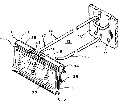
Fig. 1 is a perspective view of the merchandise
35 hook of the present invention, illustrating the label
CA 02276297 2004-06-02
-3a-
holder mounted in fixed position on a mounting plate;
Fig. 2 is a perspective view of the merchandise
hook of the present invention, illustrating the label
holder mounted on a cross bar for pivoting action;
Figs. 3, 4 and 5 are cross sectional side
elevational views of the merchandise hook of Fig. 1,
illustrating the procedure for installing the label
to holder on a fixed mounting plate;
Fig. 6 is a rear elevational view taken
generally
CA 02276297 1999-06-25
-4-
along line 6-6 of Fig. 5; and
Fig. 7 is a side elevational view of the merchandise
display hook of Fig. 2 with a label holder mounted for
pivoting action.
S Description of a Preferred Embodiment
Referring now to the drawings and specifically to
Figs. 1 and 2 thereof, the reference numeral 10 designates
a section of apertured panel board provided with a grid of
openings 11. Conventionally, the openings 11 are provided
over the entire surface of the panel 10 and are spaced
uniformly, both horizontally and vertically. A merchandise
display hook 12 is conventionally provided with mounting
lugs which are inserted through an adjacent pair of
apertures 11 in the board 10 in order to support the
merchandise hook 12 in the manner illustrated, with
operative portions of the display hook extending outward
from the face of the panel board.
The merchandise display hook 12 includes a label
holder arm 14 and a merchandise support arm 15 preferably
integrally joined by a connecting portion 19. Preferably,
the label holder arm 14 includes a downwardly turned
portion 16 at the outer end 17 thereof for attachment of a
label holder support means such as the mounting plate 18
(Fig. 1) or cross bar 20 (Fig. 2).
Mounted on the mounting plate 18 or cross bar 20 is
a plastic label holder, generally designated by the
reference numeral 30. The label holder 30 is of an
integrally extruded or coextruded, semi-rigid plastic
construction and comprises a back panel 31 joined along a
bottom edge 32 with a preferably clear front panel 33. The
front and back panels 33, 31 and the bottom edge 32 are so
CA 02276297 1999-06-25
-5-
arranged that the front panel tends to close elastically
against the front face of the back panel 31. However, by
pressing rearwardly against the bottom portion 32 the upper
lip 35 of the front panel can be sprung forward from the
back panel 31 to accommodate the placement and retrieval
of product information and pricing labels.
Referring to Figs. 3 and 7, the label holder 30
includes an upper mounting portion 34 for engagement of the
upper edge of a mounting plate 18 or a cross bar 20, and
includes a lower mounting portion 36 for engagement with
the lower edge of a mounting plate 18. The upper mounting
portion 34 includes a hinge-forming flange 37 which
projects rearwardly from the upper edge of the back panel
31 and a forwardly-facing, substantially U-shaped retaining
clip portion 38 defining a recess 39 of a size to rotatably
(i.e., loosely) pivotally receive the cross bar element 20.
At its lower edge extremity 40, the U-shaped retaining clip
portion 38 supports a downwardly and rearwardly diverging
guide flange 41. The guide flange 41 is angled downwardly
preferably at about 45 degrees with respect to the plane of
the back panel 31 and extends for a sufficient distance to
provide a relatively wide entrance 42 to guide the cross
bar 20 through the narrow entry gap 43 formed between the
back panel 31 and the lower edge extremity 40 of the U-
shaped retaining clip portion. Thus, by placing the guide
flange 41 in contact with the cross bar 20 and pressing
downward on the top of the retaining flange 37, the lower
portion of the retaining flange will be caromed open by the
guide flange 41. As soon as the cross bar 20 enters the
recess 39, the retaining flange 37 elastically closes to
the position shown in Fig. 7 so that the label holder 30 is
reliably connected to the cross bar 20 while being free to
pivot with respect thereto. Also, as seen in Figs. 1 and
2, the retaining clip portion 38 and the guide flange 41,
CA 02276297 1999-06-25
-6-
are slotted at 43 in the center of the label holder, so
that inner side edges 45 of the slot 43 straddle the wire
outward end section 17, including the downwardly-turned
portion 16, to accommodate upward pivoting of the label
S holer, and also to maintain the label holder properly
centered with respect to the label support arm 14.
Referring to Figs. 1 and 3-6, the upper mounting
portion 34 can be mounted over an upper edge 46 of a
standard mounting plate 18, with the mounting plate 18
passing through the narrow entry gap 43 between the back
panel 31 and the lower edge extremity 40 of the retaining
clip portion 38. Thus, as shown in FIG. 3, the label
holder 30 can be urged downwardly over the mounting plate
18 until the upper edge 46 of the mounting plate contacts
the hinge-forming flange 37 (i.e. the uppermost section of
the upper mounting portion 34).
As best seen in Fig. 4, the lower mounting portion 36
of the label holder 30 comprises a resilient mounting clip
50, which preferably extends across the length of the back
panel 31 of the label holder 30, parallel to the retaining
clip portion 38 and the hinge-forming flange 37. The
mounting clip 50 is integrally formed with the label holder
and the back panel 31 thereof and includes a downwardly
and rearwardly directed guide flange 52 extending from an
25 outer wall 53 of the mounting clip 50. To engage the
mounting clip 50 with the mounting plate 18, the label
holder 30 is rotated toward the mounting plate such that
the guide flange 52 of the mounting clip 50 engages the
lower edge 48 of the mounting plate 18, deflecting the
30 mounting clip 50 around the mounting plate 18.
The mounting clip 50 includes a channel 54, defined
by the back panel 31 of the label holder and an outer wall
CA 02276297 1999-06-25
53 of the mounting clip 50, to receive the lower edge 48 of
the mounting plate 18 when the label holder 30 is properly
mounted. The distance between the channel 54 of the
mounting clip 50 and the interior surface 56 of the hinge-
s forming flange portion 37 of the label holder 30 is
preferably substantially equal to the distance between the
lower and upper edges 48, 46 of the mounting plate 18 such
that the label holder 30 is substantially restrained in a
vertical direction.
In addition, the side edges 45 of the gap 43 of the
retaining clip portion 38 straddle and confine the
downwardly turned section 16 of the outward end 17 of the
label holder arm 14 to restrain the movement of the label
holder 30 in a lateral or horizontal direction.
As shown in Figs. 1 and 6, a standard mounting plate
18 may include a semi-spherical projection 56 extending
rearwardly for connection to the label support arm 14. The
side edges 45 of the gap 43 of the retaining clip portion
38 are also preferably aligned to contact the semi-
spherical projection 56 to maintain lateral alignment of
the label holder 30.
The label holder 30 can be removed by reversing the
above steps. Specifically, the bottom edge portion of the
label holder 30 is urged outward thereby disengaging the
mounting clip 50 from the lower edge 48 of the mounting
plate 18. Then, the label holder 30 is urged upward such
that the mounting clip portion 38 slides off and above the
upper edge 46 of the mounting plate 18.
Production of the novel dual purpose label holder 30
with the mounting clip 50 requires an inconsequential
increase in expense as compared to prior label holders
CA 02276297 1999-06-25
_$.
having only a retaining clip portion. However, the present
invention effectively provides a two-fold increase in the
usefulness of the label holder 30 with a corresponding
decrease in inventory and installation costs. Thus, the
novel merchandise display hook and label holder provide
significant advantages over prior designs.
Importantly, the dual purpose label holder enables a
merchandiser, desiring to take advantage of the new flip-
up style of hook and label holder to also utilize the same
label holder in conj unction with its already huge installed
base of conventional display hooks, provided with fixed
mounting plates at their outer ends. The merchandiser may
utilize a common style of label holder, without regard to
whether it is to be installed on a hook designed for flip-
up mounting of the holder, or whether the hook is of the
widely used type with a fixed mounting plate. The
merchandiser thus not only is unable to take full advantage
of the benefits of the new style of label holder, and the
convenience and cost benefits of utilizing plain paper
labels therein, but also achieves a desired uniformity of
appearance in the presentation of labels and label holders,
even though the display hooks themselves may be of
significantly different construction.
It should be understood, of course, that the specific
form of the invention herein illustrated and described is
intended to be representative only. In this respect, the
specific form of the merchandise display hook employing the
new label mounting feature may take any of a variety of
forms. Likewise, the plastic label holder itself may be
constructed in various ways consistent with the present
invention. Accordingly, reference should be made to the
following appended claims in determining the full scope of
the invention.