Sélection de la langue

Search

Sommaire du brevet 2277376 

Énoncé de désistement de responsabilité concernant l'information provenant de tiers

Une partie des informations de ce site Web a été fournie par des sources externes. Le gouvernement du Canada n'assume aucune responsabilité concernant la précision, l'actualité ou la fiabilité des informations fournies par les sources externes. Les utilisateurs qui désirent employer cette information devraient consulter directement la source des informations. Le contenu fourni par les sources externes n'est pas assujetti aux exigences sur les langues officielles, la protection des renseignements personnels et l'accessibilité.

Disponibilité de l'Abrégé et des Revendications

L'apparition de différences dans le texte et l'image des Revendications et de l'Abrégé dépend du moment auquel le document est publié. Les textes des Revendications et de l'Abrégé sont affichés :

  • lorsque la demande peut être examinée par le public;
  • lorsque le brevet est émis (délivrance).
(12) Demande de brevet: (11) CA 2277376
(54) Titre français: FILTRE, NOTAMMENT POUR L'HUILE DE LUBRIFICATION D'UN MOTEUR A COMBUSTION INTERNE
(54) Titre anglais: FILTER, IN PARTICULAR FOR THE LUBRICATING OIL OF AN INTERNAL COMBUSTION ENGINE
Statut: Réputée abandonnée et au-delà du délai pour le rétablissement - en attente de la réponse à l’avis de communication rejetée
Données bibliographiques
(51) Classification internationale des brevets (CIB):
  • B01D 29/21 (2006.01)
  • B01D 35/147 (2006.01)
  • B01D 35/31 (2006.01)
(72) Inventeurs :
  • GANDINI, SERGIO (Allemagne)
  • PETSCHL, THOMAS (Allemagne)
(73) Titulaires :
  • FILTERWERK MANN & HUMMEL GMBH
  • FILTERWERK MANN & HUMMEL GMBH
(71) Demandeurs :
  • FILTERWERK MANN & HUMMEL GMBH (Allemagne)
  • FILTERWERK MANN & HUMMEL GMBH (Allemagne)
(74) Agent: NORTON ROSE FULBRIGHT CANADA LLP/S.E.N.C.R.L., S.R.L.
(74) Co-agent:
(45) Délivré:
(86) Date de dépôt PCT: 1997-12-13
(87) Mise à la disponibilité du public: 1998-07-16
Licence disponible: S.O.
Cédé au domaine public: S.O.
(25) Langue des documents déposés: Anglais

Traité de coopération en matière de brevets (PCT): Oui
(86) Numéro de la demande PCT: PCT/EP1997/007015
(87) Numéro de publication internationale PCT: WO 1998030310
(85) Entrée nationale: 1999-07-12

(30) Données de priorité de la demande:
Numéro de la demande Pays / territoire Date
197 00 564.0 (Allemagne) 1997-01-10

Abrégés

Abrégé français

L'invention concerne un filtre, notamment pour l'huile de lubrification d'un moteur à combustion interne. Ce filtre comprend un boîtier en forme de pot, ainsi qu'un tuyau d'appui (11) disposé dans ledit boîtier et un élément filtrant (14) fixé sur ledit tuyau d'appui (11). L'élément filtrant (14) comprend essentiellement une partie filtrante pliée en accordéon et dont les faces d'about comportent des disques terminaux (15 et 16). Le boîtier assure une étanchéité directe entre lui-même et un flasque (19), le tuyau d'appui étant muni d'un filet de vissage (21).


Abrégé anglais


The invention concerns a filter, in particular for the lubricating oil of an
internal combustion engine. The filter comprises a pot-shaped filter housing,
a support pipe (11) disposed therein and a filter element (14) secured on the
support pipe (11). The filter element substantially consists of a filtering
means which is folded in zigzagged manner and comprises plates (15 and 16) at
its ends. The filter housing provides a direct seal between itself and a
flange (19), the support pipe being provided with a screw-on thread (21).

Revendications

Note : Les revendications sont présentées dans la langue officielle dans laquelle elles ont été soumises.


Claim
1. Filter, especially for the lubricating oil of an internal combustion
engine,
comprised of a pot-shaped filter housing (10), a support tube (11) disposed in
the filter housing, and a filter element (14) affixed on the support tube,
which
consists essentially of a pleated filter material with resilient end plates
(15, 16)
affixed to its end faces, wherein the filter housing (10) directly receives a
gasket
(12) for sealing between housing and flange, characterized in that the filter
element (14) is pushed onto the support tube with its end plates (15, 16)
radially
sealed against the support tube which is provided with an attachment thread
(21) and can be fastened to the flange (19) by a threaded connection.
2. Filter according to claim 1, characterized in that the support tube (11) is
screwed, welded or adhesively connected to the housing (10).
3. Filter according to one of the foregoing claims, characterized in that a
filter
element bypass valve (24) and/or a return flow check valve (25) is disposed in
the support tube (11).
4. Filter according to one of the foregoing claims, characterized in that a
catch
element is provided on the support tube (11) for positioning the filter
element
(14).
5. Filter according to one of the foregoing claims, characterized in that on
the end
plate (16) of the filter element (14) which faces the flange (19) an element
is
provided for preventing raw oil from flowing back and/or an element is
provided
for the removal of the filter element.
6. Filter according to one of the foregoing claims, characterized in that the
housing
(10) and/or the support tube (11) is manufactured from an injection molded
synthetic resin.

Description

Note : Les descriptions sont présentées dans la langue officielle dans laquelle elles ont été soumises.

CA 02277376 1999-07-12
Article 34 Amendment
Filter, in Particular for the Lubricating Oil of an Internal Combustion Engine
The invention relates to a filter, in particular for the lubricating oil of an
internal
combustion engine in accordance with the preamble of patent claim 1.
Such a filter is, for example, known from DE 41 39 680. This filter has
according to
Figure 1 of the publication, an annular filter cartridge which is pushed onto
a central
tube with the assistance of gaskets 18, 19. The central tube is connected fast
with a
bell housing 11, by means of which a simplification of the structural assembly
can be
achieved in a high degree of economy. The bell housing is attached, for
example to
a motor block, by means of an adapter 15. By using different adapters, a
flexible
utilization of the filter with different sizes of connectors is possible.
However, the disclosed structure also has disadvantages. As a result of the
use of
the adapter, it becomes necessary to incur an additional sealing expense in
the form
of gasket rings 14, 24. Also, the gaskets, which are used for sealing the
filter
cartridge, have a complex structure, so that no standard parts can be used.
The invention therefore is addressed to the object of providing a filter,
especially for
lubricant oil of an internal combustion engine, which will consist of few
parts and thus
will be easy to service as well as inexpensive. This object is achieved by the
features of patent claim 1.
The substantial advantage of the invention is to be seen in the fact that the
filter in
the basic version consists of four component parts, namely a housing, a center
tube,
a metal-free cartridge and a gasket. In a preferred manner the housing is an
injection molded synthetic resin part. This part is very inexpensive to
manufacture
and can also be made, for example, from recycled material.

CA 02277376 1999-07-12
Internal Combustion Engine
The invention relates to a filter, in particular for the lubricating oil of an
inte~al combustion
engine.
EP 0 526 932 B 1 discloses an oil filter. This consists substantia of a
housing in which
different components, such as screw threaded fastening me , filter cartridge,
supporting
body, cover plates and gaskets, are contained. To replac he oil filter
cartridge, such an oil
filter can be disassembled to its component parts an an be provided with a new
cartridge.
A disadvantage of the known oil filter lies in a large number of component
parts, resulting
in the danger that, when the oil filter cart ' ge is replaced, parts may be
lost or the assembly
may not be properly done.
The invention therefore is ad ssed to the object of providing a filter,
especially for the
lubricant oil of an interna ombustion engine, which will consist of few parts
and thus will
be easy to service as 1 as inexpensive.
This object isy~hieved by the features of the main claim.
The s stantial advantage of the invention is to be seen in the fact that the
filter in the basic
ve ion consists of four component parts, namely a housing, a center tube, a
metal-free
artridge and a gasket. In a preferred manner the housing is an injection
molded synthetic
resin part. This part is very inexpensive to manufacture and can also be made,
for example,
The filter is provided with a replaceable filter element. The filter element
is merely pushed
over the supporting tube and has a radial gasket.
The entire housing is open toward a flange. This means that no end plate
closing the pot-
shaped housing is necessary. By the elimination of the end plate, direct
access to the filter
element is assured, so that it can be replaced without special tools.

CA 02277376 1999-07-12
2
In one embodiment of the invention provision is made for the support tube to
be threaded into
the housing or, when inj ection molded plastic is used, for it to be welded by
ultrasound or
high frequency or adhesively joined.
The filter element in one embodiment of the invention is provided with end
plates which are
made of nitrite rubber and thus have a high elasticity. In this way additional
sealing means
can be omitted. The end plates themselves produce a radial sealing of the
filter element. In a
preferred embodiment a filter element bypass valve can be arranged on the
supporting tube.
The possibility also exists for arranging a non-return valve in the supporting
tube. Both
valves are of simple construction and consist substantially of a valve spring
and a valve plate.
Usually the filter element is mounted floatingly on the support tube, i.e. its
axial position is
defined by the abutment on the bottom of the housing. For precise fixation of
the filter
element, a catch element can be provided on the support tube, which prevents
displacement
of the filter element. It is also possible to provide a sleeve or the like on
the support tube for
the fixation of the filter element.
To prevent raw oil, i.e. oil that has not yet been filtered, from flowing in
reverse direction, the
end plate facing the flange can be equipped with a non-return valve, for
example in the form
of a one-piece profile gasket. In this way the filter is effectively prevented
from running
empty.
These and additional features of preferred embodiments of the invention will
be found not
only in the claims but also in the description and the drawings, and the
individual features can
each be realized individually or together in the form of subcombinations in
the embodiments
of the invention and in other fields, and can constitute advantageous as well
as independently
patentable embodiments, for which protection is hereby claimed.
The invention will be explained in further detail hereinafter with reference
to illustrative
embodiments.
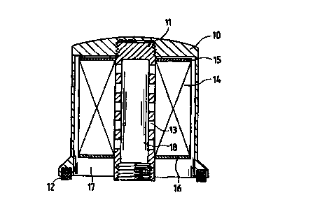
Figure 1 shows a sectional view of a simple filter,
Figure 2 shows the simple filter depicted in Figure 1 with additional
elements.
The filter according to Figure 1 comprises a pot-shaped housing 10. Into this
housing a
support tube 11 is screwed. The housing carries a profile gasket 12 on the end
facing a

CA 02277376 1999-07-12
3
mounting flange. A filter element 14 is pushed onto the support tube 11 which
is provided
with openings 13. This filter element 14 is comprised of a pleated filter
material which is
provided at the ends with end plates 15 and 16. In conjunction with the outer
surface of the
support tube the end plates form a radial seal at their inner annular opening
and thereby seal
the raw liquid area 17 from the clean liquid area 18. The filter element 14 is
merely slipped
onto the support tube 11. The sealing areas of the end plates provide for a
secure retention of
the filter in the filter housing.
In Figure 2 a filter with additional features is shown. The filter is fastened
on a flange 19, a
hollow screw 20 being provided on the flange which meshes with the thread 21
on the
support tube 11. The introduction of the liquid to be cleaned takes place
through the opening
22, and the return flow takes place through the already mentioned hollow screw
20 and its
opening 23.
In the support tube 11 is a filter element bypass valve 24 and a back-flow
check valve 25.
The check valve consists essentially of a spring 26 and a valve plate 27. A
check valve for
the raw liquid in the form of a sealing lip 28 is disposed on the filter
element 14, i.e. on its
end plate 16,. Also, two removal tabs 29 and 30 are provided on the end plate
16. These
facilitate the removal of the filter element 14. The filter element 14 can
thus be pulled off
from the support tube manually or with a simple tool.
The replacement of the filter element can be carried out in different ways. As
already
mentioned, it is possible to pull off the filter element 14 from the support
tube and replace it
with a new one. But there is also the alternative possibility of releasing the
connection
between the support tube 11 and housing 10, unscrewing the support tube, and
pulling the
filter element off at the opposite end of the support tube. It also should be
mentioned that
there is also the possibility of replacing the entire filter with a new one.
The used filer can
be delivered to a recycling plant.

Dessin représentatif
Une figure unique qui représente un dessin illustrant l'invention.
États administratifs

2024-08-01 : Dans le cadre de la transition vers les Brevets de nouvelle génération (BNG), la base de données sur les brevets canadiens (BDBC) contient désormais un Historique d'événement plus détaillé, qui reproduit le Journal des événements de notre nouvelle solution interne.

Veuillez noter que les événements débutant par « Inactive : » se réfèrent à des événements qui ne sont plus utilisés dans notre nouvelle solution interne.

Pour une meilleure compréhension de l'état de la demande ou brevet qui figure sur cette page, la rubrique Mise en garde , et les descriptions de Brevet , Historique d'événement , Taxes périodiques et Historique des paiements devraient être consultées.

Historique d'événement

Description Date
Inactive : CIB de MCD 2006-03-12
Demande non rétablie avant l'échéance 2003-12-15
Le délai pour l'annulation est expiré 2003-12-15
Réputée abandonnée - omission de répondre à un avis sur les taxes pour le maintien en état 2002-12-13
Inactive : Abandon.-RE+surtaxe impayées-Corr envoyée 2002-12-13
Inactive : Page couverture publiée 1999-09-30
Lettre envoyée 1999-09-21
Inactive : CIB en 1re position 1999-09-02
Inactive : Lettre de courtoisie - Preuve 1999-08-24
Inactive : Notice - Entrée phase nat. - Pas de RE 1999-08-19
Demande reçue - PCT 1999-08-16
Inactive : Transfert individuel 1999-08-04
Modification reçue - modification volontaire 1999-07-12
Demande publiée (accessible au public) 1998-07-16

Historique d'abandonnement

Date d'abandonnement Raison Date de rétablissement
2002-12-13

Taxes périodiques

Le dernier paiement a été reçu le 2001-11-23

Avis : Si le paiement en totalité n'a pas été reçu au plus tard à la date indiquée, une taxe supplémentaire peut être imposée, soit une des taxes suivantes :

  • taxe de rétablissement ;
  • taxe pour paiement en souffrance ; ou
  • taxe additionnelle pour le renversement d'une péremption réputée.

Veuillez vous référer à la page web des taxes sur les brevets de l'OPIC pour voir tous les montants actuels des taxes.

Historique des taxes

Type de taxes Anniversaire Échéance Date payée
Taxe nationale de base - générale 1999-07-12
Enregistrement d'un document 1999-08-04
TM (demande, 2e anniv.) - générale 02 1999-12-13 1999-11-25
TM (demande, 3e anniv.) - générale 03 2000-12-13 2000-11-29
TM (demande, 4e anniv.) - générale 04 2001-12-13 2001-11-23
Titulaires au dossier

Les titulaires actuels et antérieures au dossier sont affichés en ordre alphabétique.

Titulaires actuels au dossier
FILTERWERK MANN & HUMMEL GMBH
Titulaires antérieures au dossier
SERGIO GANDINI
THOMAS PETSCHL
Les propriétaires antérieurs qui ne figurent pas dans la liste des « Propriétaires au dossier » apparaîtront dans d'autres documents au dossier.
Documents

Pour visionner les fichiers sélectionnés, entrer le code reCAPTCHA :


Pour visualiser une image, cliquer sur un lien dans la colonne description du document. Pour télécharger l'image (les images), cliquer l'une ou plusieurs cases à cocher dans la première colonne et ensuite cliquer sur le bouton "Télécharger sélection en format PDF (archive Zip)" ou le bouton "Télécharger sélection (en un fichier PDF fusionné)".

Liste des documents de brevet publiés et non publiés sur la BDBC .

Si vous avez des difficultés à accéder au contenu, veuillez communiquer avec le Centre de services à la clientèle au 1-866-997-1936, ou envoyer un courriel au Centre de service à la clientèle de l'OPIC.


Description du
Document 
Date
(aaaa-mm-jj) 
Nombre de pages   Taille de l'image (Ko) 
Dessin représentatif 1999-09-27 1 9
Dessins 1999-07-12 1 28
Page couverture 1999-09-27 1 44
Abrégé 1999-07-12 1 13
Description 1999-07-12 4 189
Revendications 1999-07-12 1 40
Rappel de taxe de maintien due 1999-08-17 1 114
Avis d'entree dans la phase nationale 1999-08-19 1 208
Courtoisie - Certificat d'enregistrement (document(s) connexe(s)) 1999-09-21 1 140
Rappel - requête d'examen 2002-08-14 1 115
Courtoisie - Lettre d'abandon (taxe de maintien en état) 2003-01-13 1 176
Courtoisie - Lettre d'abandon (requête d'examen) 2003-02-24 1 167
Correspondance 1999-08-19 1 15
PCT 1999-07-12 14 499