Note : Les descriptions sont présentées dans la langue officielle dans laquelle elles ont été soumises.
. ;
CA 02277662 1999-07-14
24.790
NUCLEAR MAGNETIC RESONANCE LOGGING WITH AZIMUTHAL
RESOLUTION USING GRADIENT COILS
Field of the Invention
This invention relates to the field of well logging and, more particularly, to
a
method and apparatus for determining nuclear magnetic resonance logging
characteristics
of earth formations surrol;mding a borehole, as a function of angular position
about the
borehole, either during the; drilling of the borehole (using an MWD or LWD
device) or
to after drilling (using a wireline tool).
Background of the Invention
Borehole nuclear magnetic resonance measurements provide different types of
information about a reservoir. First, the measurements provide an indication
of the
amount of fluid in the formation. Second, the measurements present details
about whether
the fluid is bound by the l:ormation rock or unbound and freely producible.
Finally, the
measurements can be used to identify the type of fluid - water, gas, or oil.
One approach to obtaining nuclear magnetic resonance measurements employs a
locally generated static magnetic field, Bo, which may be produced by one or
more
2o permanent magnets or electromagnets, and an oscillating magnetic field, B,,
which may
be produced by one or more RF antennas, to excite and detect nuclear magnetic
resonance
properties to determine porosity, free fluid ratio, and permeability of a
formation. See
T.S. Pat. Nos. 4,717,878 issued to Taicher et al. and 5,055,787 issued to
Kleinberg et al.
CA 02277662 2001-10-22
77483-31
Nuclear spins align with the applied field B~ with a time constant of T,
generating a net
nuclear magnetization. The angle between the nuclear magnetization and the
applied held
can be changed by applying an RF field. B, , perpendicular to the static field
Bo. The
frequency of the RF rield is equal to the Larmor frequency given by c~~--,rB~
where y is the
~yromagnetic ratio. After appiication of an RF pulse, the magnetization begins
to precess
around B~ and produces a detectable signal in the antenna.
Another approach to obtaining nuclear magnetic resonance measurements
employs a locally generated static magnetic field, B~, which may be produced
by one or
more permanent magnets or elec~somagnets. and an azimuthally-oriented
oscillating
to masnetic field. B,, which may be produced by one or more RF antenna
segments that
transmit and/or receive from difFerent circumferential sectors of the logging
device. See
U.S. Patent Nos. 5,977,768 and 6,255,817
assi~ned~to Schlumberger Technology Corporation. Typical long echo trains ~~
600
spin-echoes) are unobtainable with a rotating azimuthai antenna. Since the
antenna is
t~ only properiv positioned in the measurement direction during a short time,
the signal
decays faster due to rotation of the tool than it would due to formation
properties alone.
U. S. Pat. No. ~,i96.~~= issued to Kleinberg et al. describes a nuclear
magnetic
logging device which includes permanent magnets. an RF antenna. and a coil for
generating a magnetic field ;radient. The technique described in the ''_'~'_'
patent utilizes
.o pulsed magnetic field gradients to obtain information regarding diffusion
properties of the
formation fluids. If internal gradients are present in the formation. a pulse
sequence is
applied to reduce or substantially eliminate the effect of internal gradients
in the
,
rt
CA 02277662 1999-07-14
24.790
formation. The '252 patE:nt does not identify a method for using the coil to
obtain an
azimuthal NMR measurement.
U. S. Pat. No. 5,212,447 issued to Zvi Paltiel describes a nuclear magnetic
logging device which includes permanent magnets and an RF antenna coil. The
'447
patent requires a magnetic; field gradient coil to determine a diffusion
coefficient, i.e., the
rate at which molecules of a material randomly travel within the bulk of the
same
material. The '447 patent employs the diffusion coefficient to determine at
least one of
the following petrophysical parameters: water/hydrocarbon discrimination,
water and
hydrocarbon saturation levels, permeability, pore size and pore size
distribution, oil
to viscosity, a measure of the average increase in electrical resistance due
to the formation
tortuosity, and q-space irr~aging of the formation. The '447 patent does not
identify a
method for using the coil to obtain an azimuthal NMR measurement.
A primary object of this invention is to obtain an azimuthal NMR measurement.
This measurement may be used to determine formation characteristics such as
porosity,
bound fluid volume, T~, T,, and permeability. Being able to measure the
azimuthal
variation of these characteristics is useful for interpreting heterogeneous
formations and
performing geologically based steering in deviated or horizontal boreholes.
Another object of the invention is to improve the vertical resolution of the
tool
using at least one gradient coil.
3
CA 02277662 1999-07-14
24.790
Summary of the Invention
The above disadvantages of the prior art are overcome by means of the subject
invention for an apparatus and method for determining nuclear magnetic
resonance
logging characteristics of earth formations surrounding a borehole, as a
function of
angular position about the borehole. The subject invention also performs
azimuthal
magnetic resonance imagvng. A wireline or logging-while-drilling apparatus
within a
borehole traversing an earth formation determines a formation characteristic
by obtaining
a nuclear magnetic resonance measurement from a region of investigation. The
apparatus
includes a means for producing a static magnetic field, Bo. An RF antenna
produces an
to oscillating field, B,, in the same region of the formation as the static
magnetic field to
obtain the NMR measurement. The apparatus includes at least one gradient coil.
The
magnetic field produced by the gradient coil is substantially parallel to the
static magnetic
field, Bo.
When a current pulse is applied to the gradient coil, the spins in a portion
of the
investigation region will either completely or incompletely dephase. The
geometry of the
gradient coil determines whether the spins experience radial, azimuthal, or
axial
dephasing. For complete dephasing, the gradient field will alter the phase of
spins in the
portion of the investigation region by spatially varying the magnetic field
strength so that
a net magnetization within 'the section is zero. For incomplete dephasing, the
gradient
2o field will alter the phase of spins in the portion of the investigation
region so that a net
magnetization over the portion is non-zero and has a different phase than the
net
magnetization in the remaining portion of the investigation region.
4
CA 02277662 2002-11-15
77483-31
A cross-section of the formation is partitioned to
form either a plurality of angular distance segments, axial
segments, or radial segments around the borehole. In
addition, a radial partitioning of the borehole is
described. A pulse sequence is applied to the formation
under investigation. The pulse sequence comprises a
symmetric phase alternated pulse sequence, i.e., a
measurement without using the gradient coils, and/or a
gradient phase alternated pulse sequence, i.e., a
measurement using the gradient coils. The gradient coils
dephase spins in at least one of the segments. In one
embodiment, an azimuthal measurement is created by
subtracting the gradient measurement from the symmetric
measurement. In a second embodiment, the azimuthal
measurement is created by combining different single
quadrant spoiling measurements. In a third embodiment, a
plurality of azimuthal bins are defined and each NMR
measurement is added to the content of the buffer associated
with the bin in which the measurement was taken.
A broad aspect of the invention provides an
apparatus for determining a nuclear magnetic resonance
property in an investigation region of earth formations
surrounding a borehole, comprising: a) a logging device
moveable through the borehole; b) means in the logging
device for applying a static magnetic field
circumferentially around the borehole and into the
investigation region; c) antenna means in the logging device
for applying an RF magnetic field circumferentially around
the borehole and into the investigation region whereby the
antenna means induces a plurality of spin-echo signals from
nuclei of the formation; d) gradient means in the logging
device for applying a magnetic field gradient to dephase
spins in a portion of the investigation region; and e) means
5
~ CA 02277662 2002-11-15
77483-31
for detecting nuclear magnetic resonance signals from the
investigation region.
Another broad aspect of the invention provides a
method for measuring a nuclear magnetic resonance property
in an investigation region of earth formations surrounding a
borehole, comprising the steps of: a) drilling a borehole in
the formation; b) applying a static magnetic field into the
investigation region; c) applying an RF magnetic field into
the investigation region; d) inducing a plurality of spin-
echo signals from nuclei of the formation; e) applying a
magnetic field gradient to dephase spins in a portion of the
investigation region; and f) detecting nuclear magnetic
resonance signals from the investigation region.
5a
L
CA 02277662 1999-07-14
24.790
Brief Description of the I)rawinQs
The advantages oP the present invention will become apparent from the
following
description of the accompanying drawings. It is to be understood that the
drawings are to
be used for the purpose of illustration only, and not as a definition of the
invention.
In the drawings:
Fig. 1 illustrates a logging-while-drilling bottom hole assembly;
Fig. 2 illustrates a measurement-while-drilling apparatus;
Fig. 3 represents a flow chart of the Quadrant/Coil Position Determination
Program;
l0 Fig. 4 represents a nuclear magnetic resonance logging-while-drilling tool;
Fig. 5 dia~;rams the electronic circuitry used in conjunction with the
gradient coils of thE; subject invention;
Fig. 6 illustrates the gradient coils in one embodiment of the subject
invention;
Fig. 7a illustrates the pulse sequence used in a preferred embodiment of
the invention;
Fig. 7b represents a simulation of the rotation effect on the TZ spectrum
using an azimuthal antenna;
Figs. 8a-8b illustrate a gradient coil geometry for radial dephasing and the
resulting magnetic field strength;
Figs. 9a-9b illustrate a gradient coil geometry for azimuthal dephasing and
the resulting magnetic field strength;
6
CA 02277662 1999-07-14
24.790
Figs. 1 Oa-;~ Ob illustrate a gradient coil geometry for axial dephasing and
the resulting magnetic field strength; and,
Figs. l l a- l l b represent the azimuthal distribution of the NMR signal for
incomplete and complete dephasing.
CA 02277662 1999-07-14
24.790
Detailed Description of the Preferred Embodiments
Referring to Figure 1, there is illustrated a logging-while-drilling apparatus
10 in
which embodiments of the invention can be practiced. A drill string 12 is
disposed within
borehole 14 and includes <i drill bit 16 at its lower end. The drill string
12, and the drill
bit 16 attached thereto, is rotated by a rotating table (not shown) which
engages a kelly
(not shown) at the upper end of the drill string 12. Alternatively, the drill
string 12 may
be rotated from the surface; by a "top drive" type of drilling rig. In either
case, a device
pumps drilling fluid or mud into the drill string downward through a channel
in the center
of drill string 12. The drilling fluid exits the drill string 12 via ports in
the drill bit 16 and
then circulates upward in t:he region between the outside of the drill string
12 and the
periphery of the borehole 14. As is well known, the drilling fluid thereby
carries
formation cuttings to the sw~ace of the earth.
Tools designed for formation evaluation while drilling 20 (LWD), drill string
characterization while drilling 22 (MWD), or a combination of both (LWD/MWD)
are
t5 connected to the drill string 12. A typical MWD tool 22 measw-es and/or
computes the
direction, inclination, and rotational orientation of the bottom hole assembly
("tool
face"). An MWD tool useful with the subject invention is described, for
example, in U. S.
5,473,158. The driving electronics module 24 and acquisition and processor
electronics
module 26 are coupled to the L WD tool 20. These modules 24, 26 control and
obtain
2o measurement information therefrom. The LWD tool 20 contemplated by the
subject
invention is described below.
Figure 2 illustrates the MWD tool 22 which includes magnetometers HX and HY
(32, 34) oriented along x anc( y axes of the tool. Such x and y axes are in
the plane of a
8
2
CA 02277662 1999-07-14
24.790
radial cross section of the tool. A z-axis of the tool is oriented along its
longitudinal axis.
In a similar way, accelerometers Gx and GY of the accelerometer package 36
(which also
includes an accelerometer along the z-axis of the tool) are oriented along the
x and y axes
of the tool. A microcomputer 30 responds to Hx and Hs, signals and GY and GY
signals to
constantly determine an a~agle ~ between an H' vector and the G' vector, in
the cross
sectional plane of the MVVD tool 22. The H' vector represents that portion of
a vector
pointed to earth's magnetic; north pole which is projected onto the x-y plane
of MWD tool
22. The G' vector represents the down component in the cross sectional plane
of tool 22
of the earth's gravity vector. A signal representative of such angle ~ is
constantly
communicated to the downhole computer 30 (which includes a Quadrant/Coil
Position
Determination program).
Figure 3 is a flow chart which describes the Quadrant/Coil Position
Determination
Program 100. As explained above, an angle ~ is constantly computed between the
H'
vector (a constantly directed vector in the x-y plane for a vector directed to
earth's
magnetic pole) and a G' vector ( a constantly directed down vector in the x-y
plane of a
vector directed to the earth's gravitational center). As the device rotates in
the borehole,
the x and y axes of the device rotate at the angular speed of the drill string
12 so the x and
y components of the I-i' vector and G' vector are constantly changing with
time.
Further, as the device rotate, in borehole 14, an angle A(t) is constantly
formed between
the tool x-axis and such H' vector. The angle 8(t) is determined from the F~
and Hy,
signals from magnetometers 32 and 34 and the angle varies with time because it
is
measured from the x-axis of the MWD tool 22 (and the LWD tool 20) to the H'
vector.
9
CA 02277662 1999-07-14
24.790
At step 102, the down vector angle, LD(t) , is determined in Quadrant/Coil
Position Determination program 100, according to the following relationship,
as a
function of the x and y axes and time:
e(t) = Cos-~ H'T ~t )
r (1)
~Hx (t)2 + Fly (t)z )
The angle of the down vector is determined in the program as LD(t) = A(t) - ~.
At step 104, four qua~.drants may be defined by angular ranges about the
periphery
of the tool:
QsoT(t) = LD(t) -45° to LD(t) +45°
QL~.(t) = Llri(t) +45° to LD(t) +135°
to QTOP(t) = LD(t) +135° to LD(t)+225°
Q~o,.~.(t) = Ll~(t) +225° to LD(t) -45°.
The term "quadrant" is used to illustrate the invention where four 90°
angular distance
segments are defined around. the 360° circumference of the MWD device
or the LWD
tool. Other angular distance segments may be defined, either lesser or greater
in number
than four, and such segments may be unequal.
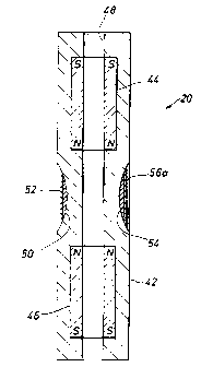
Figure 4 illustrates a nuclear magnetic resonance (IVMR) logging-while-
drilling
tool 20 in accordance with a preferred embodiment of the invention. The tool
20 is
rotationally symmetric about the axis 40 of the drill collar 42, which is
substantially
aligned with the axis of the borehole. A static magnetic field is produced by
tubular,
2o axially polarized, permanent magnets 44, 46 that are mounted inside the
drill collar 42.
CA 02277662 1999-07-14
24.790
Channel 48 located inside the tool permits drilling mud to flow toward the
drill bit. In the
region between the magnets 44, 46, there is a recessed area 50. An RF antenna
52 is
provided in the recessed area 50. Preferably, the antenna 52 comprises a coil
wound
circumferentially around the recessed area. The RF field created by such a
coil
arrangement is substantially axisymmetric. It is within contemplation of the
subject
invention to utilize the antenna 52 for detecting NMR signals. However, a
separate
antenna or receiver may be used to detect the signals. A non-conductive
material 54 is
provided in the recessed area 50 beneath the antenna 52. The material 54 is
preferably a
ferrite to increase the efficiency of the antenna 52. Alternatively, the
material 54 may
to comprise a plastic, rubber, or a reinforced epoxy composite material.
Still referring to Figure 4, in order to obtain azimuthal NMR measurements, at
least one gradient coil 56 is arranged in the recessed area 50. In a preferred
embodiment
of the invention, three gradient coils 56a, 56b, and 56c are positioned
circumferentially
around the recessed area and separated by an angular distance segment of
120°. Other
quantities of gradient coils may be defined, either lesser or greater in
number than three,
and such coils may be separated by angular distances other than 120°
and/or unequal
angular segments. Each coil 56a, 56b, and 56c is constructed with loops of
wire which
conform to the curvature of the outer surface of the material 54. The magnetic
field
produced by each gradient coil 56a, 56b, and 56c in a region of the formation
facing the
coil is substantially parallel to the static magnetic field produced by the
permanent
magnets 44, 46. It should tie noted that the method and gradient coils of the
subject
invention can also be used with any tool that generates a rotationally
symmetric static
z .
CA 02277662 1999-07-14
24.790
magnetic field, for examF>le, the tools disclosed in U. S. Pat. Nos. 5,757,186
issued to
Taicher et al., and 5,280,243 issued to Melvin Miller.
Figure 5 is a diagram of the circuitry included in the driving electronics
module
24 for use in conjunction with the gradient coils 56a, 56b, and 56c. The
driving
electronics includes a high voltage power supply 60 and capacitor 62. Switches
S,, S2,
and S3 are under the control of timing control/coil selection hardware 64. The
gradient
coils 56a, 56b, and 56c are coupled, via the switches, to the timing
control/coil selection
hardware 64.
As Figure 6 illustrates, the gradient coils 56a, 56b, and 56c are oriented at
to known angles, a,,a~, and a3, respectively, from the x-axis. Thus, the angle
of each
gradient coil is a constant angle, a, as measured from the x-axis of the tool
20.
Accordingly; the computer program 100 determines which quadrant a coil 56a,
56b, or
56c is in by comparing its angle from the x-axis and 8(t) with a quadrant
defined with
respect to the x-axis. The clown vector, D , and four quadrants, QBOT. Qc~cxr.
QTOP ~ ~d
QL~. are fixed in space, but are defined as a function of time with the
turning x and y
a<Yes of the LWD device.
As is known to those skilled in the art, in the basic NMR measurement, a pulse
sequence
is applied to the formation under investigation. In U. S. Pat. No. 5,96,274
issued to
Abdurrahman Sezginer and U. S. Pat. No. 5,023,551 issued to Kleinberg et al.,
a pulse
2o sequence, such as the Carr-Purcell-Meiboom-Gill (CPMG) sequence, first
applies an
excitation pulse, a 90° pulse;, to the formation that rotates the spins
into the transverse
plane. After the spins are rol:ated by 90' and start to dephase, the carrier
of the refocusing
12
CA 02277662 1999-07-14
24.790
pulses, the 180° pulses, is phase shifted relative to the carrier of
the 90° pulse sequence
according to the following; relationship:
r9o=z -ra -~r~goy -t, -echoro~,; -r2, , where the bracketed expression is
repeated for
n
re=1,2,...N, where N is thf; number of echoes collected in a single CPMG
sequence and
the echo spacing is re~,o = 2r~p = r~$o. +r, +r2 . 90tX denotes an RF pulse
that causes the
Y
spins to rotate by a 90° angle about the +x-axis, as commonly defined
in the rotating
frame of magnetic resonance measurements (phase alternated). The time between
application of the 90° pulse and the 180° pulse, to, is less
than t~, half the echo spacing.
The CPMG sequence enables acquisition of a symmetric measurement (i.e., a
t0 measurement without using; the gradient coils). The exact timing
parameters, to, t,, and t2,
depend on various factors (e.g., the shape of the applied pulses).
In the subject invention, a current pulse applied to gradient coil 56a, 56b,
or 56c
generates an additional magnetic field, substantially parallel to the static
magnetic field.
The current pulse is applied between the first 90° and the 180°
phase reversing pulse. This
additional field causes an additional phase shift for the spins. Since .the
180° phase
reversing pulse does not cornpensate for the additional phase shift, the spins
subjected to
the additional field do not form a spin-echo. However, for spins not subjected
to the
additional field, a spin-echo occurs at time 2t~p with spin-echoes of
successively lower
amplitude occurring at time t~ after each phase reversing pulse. The pulse
sequence is
r9o=~ -ro -s-ro -[r~go. -r, -echo's -r2, , where ro is the time between the
90° pulse and
n
the gradient pulse of duration 8 , ro is the time between the gradient pulse
and the 180°
13
CA 02277662 2001-10-22
77483-31
reversing pulse, and r,; -~ -r~ = r~ . In addition. as described before. due
to off resonance
effects, out of phase magnetization vanishes within a few echoes. Due to the
succeeding
~so Y pulses and the inhomogeaeous fields, the Y-component of the ~1VIR signal
will decay
within a few echoes. Therefore. we focus only on the y-component of the
signal. Thus,
J neglecting relaxation, the first VVIR echo signal can be represented as:
1
Signa! _ ~mL f E~3 (.~!° +i:~f~ ~(r)e;cp~-i~G(r)b~dc(r)~,
where i is the imaginary complex unit: ~ is the gvromagnetic ratio: .vlr and
:v1° are
respectively :c and v components of the magnetization at location r at the
time of the first
echo in the absence of the ~adieat pulse: G(r) is the component of the
gradient field
to parallel to B~ at the same location: v is the duration of the 3adient
pulse: and dcf r)
denotes the differential sensitivity of the ~iI~LR sonde. Figure ?b shows a
simulation of
the rotation effec: on the T: spectrum using an azimuthal antenna. This
demonstrates that
an accurate T, spec~um is unobtainable with a rotating azimuthal antenna.
However, with
the axisvmmetric antenna and gradient coil of the subject invention. it is
possible to
t5 obtain a better T= spectrum.
The acquisition of phase alternated pulse sequences may be eliminated by using
the RingKiller pulse sequence described in U. S . Patent No . 6 , 121, 774
assigned to Schlutnberger Technology Corporation. With that
sequence. during a first time period of a single pulse sequence, the Ni~IR
measurement
o includes the desired spin-zchoes and the undesired effects, that is.
ringing, measurement
noise. and baseline shift. Durin; a second time period of the single pulse
sequence. the
t-t
CA 02277662 1999-07-14
24.790
spin-echoes are eliminated. but not the undesired effects. Using the signal
collected during
the second time period, the signals measured during the first time period acre
corrected to
eliminate the ringing component, measurement noise, and baseline shift. It is
within
contemplation of this invention to use any combination of sequences to
eliminate ringing,
including, but not limited t:o, the ringing suppression method described in WO
98/43064
assigned to Numar Corporation.
Depending upon the; geometric design of the gradient coils 56a, 56b, and 56c,
the
duration, and the strength of the current pulse applied to the coil 56a, 56b,
or 56c, the
spins in a sensitive region, (e.g., one quadrant) will dephase in one of the
following
1 o manners: radial dephasing, azimuthal dephasing, axial dephasing, or
incomplete
dephasing. Firing a current of sufficient magnitude through the gradient coils
causes the
additional phase shift of the spins subjected to the magnetic field gradient
of the coil to be
distributed over a range from -180° to 180° and possibly vary by
several multiples of
360° over the sensitive region. For radial, axial, and azimuthal
dephasing, a varying
additional phase angle is generated so that the response of spins in a
sensitive region (e.g.,
one quadrant) averages to zero.
Figure 8a illustrates ,~ gradient coil geometry useful for radial dephasing.
This is
achieved by generating a st7-ong gradient field with a single coil so that the
additional
phase due to the field of the; gradient coil 56a, 56b, or 56e varies within
the thickness
(i.e., shell) of the sensitive region by at least 2n. Figure 8b depicts the
magnetic field
strength across the shell. In the portion of the shell close to the gradient
coil, spins rotate
faster than spins toward an outside portion of the shell.
CA 02277662 1999-07-14
24.790
Figure 9a illustrates a gradient coil geometry useful for azimuthal dephasing.
This
is achieved by generating a. strong gradient field with two coils connected in
series such
that the current flows in opposite directions in the two coils. When opposite
currents are
flowing in the two coils, the; spins in the vicinity of one coil rotate faster
than the average
spins and the spins in the vicinity of the other coil rotate more slowly than
the average so
that the additional phase varies over the azimuth of a part of the sensitive
region. Figure
9b depicts the magnetic field strength along the azimuthal angle cp.
Rotating the azimutrtal dephasing coil by 90° results in a gradient
coil geometry
useful for axial dephasing (See Figure 10a). The phase angle varies along the
longitudinal
Io axis of the tool. Figure lOb depicts the magnetic field strength along the
length of the
tool. In all three cases (radial, azimuthal, and axial dephasing), the spatial
average of the
magnetization over the sensiaive region is zero and therefore does not
contribute to the
measured NMR signal.
In the case of incomplete dephasing, the strength of the current through the
gradient coil 56a, 56b, or 56c: is weaker than the previously described three
cases, and the
additional phase shift does not vary strongly enough to cause a complete
averaging out to
zero of the magnetization over the sensitive region. Nevertheless, the
additional gradient
field causes a phase shift of the spins in the sensitive region with respect
to the phase of
the spins in the other regions aground the tool (i.e., the spins not subjected
to the additional
Zo field). In this case, the average of the magnetization over the sensitive
region is non-zero
and has a different phase than the net magnetization in the remaining portion
of the
investigation region and the spins still experience a phase shift. Since the
detected NMR
16
CA 02277662 1999-07-14
24.790
signal is phase sensitive (i.e., only contributions with a certain phase are
measured), an
additional phase shift in tlhe direction of the gradient coil 56a, 56b, or 56c
is sufficient to
perform an azimuthal measurement. Incomplete dephasing is possible with any of
the
geometric designs shown iin Figures 8a, 9a, and 10a.
The gradient coila offer a number of advantages for obtaining azimuthal
measurements. First, a coiil only has to be properly positioned in a desired
quadrant for
the duration of the gradient pulse rather than during the entire pulse
sequence. Second,
because the spin-echoes a~~e detected by the axisymmetric antenna, long echo
trains can
be recorded while the tool rotates in the borehole. Third, the coil simplifies
the design of
to an NMR-LWD tool becauae the coil does not have the tuning requirements of
an RF
antenna. Fourth, the same antenna can be used to make symmetric and
axisymmetric
measurements. Fifth, the coils can be used to obtain NMR measurements with
excellent
spatial resolution, particula~~iy vertical resolution.
Different modes for obtaining azimuthal NMR measurements are contemplated by
the present invention. For a. "simple spoiling" mode, at least one coil is
used to spoil the
spins in a selected quadrant, however, more coils may be used to spoil a
plurality of
quadrants. In either case, trvo measurements are obtained: a symmetric phase
alternated
pulse sequence (PADS) with a fixed wait time followed by a gradient PAPS,
having a
variable wait time, with the selected quadrant spoiled by firing the coil in
the quadrant. In
2o a preferred embodiment of the invention, the aforementioned gradient pulse
sequence is
used. The azimuthal measurement is created by subtracting the gradient
measurement
from the symmetric measurement. In this mode, one symmetric measurement is
obtained
for every two PADS and one azimuthal scan is obtained for every eight PADS.
The
17
CA 02277662 1999-07-14
24.790
measurement noise for the azimuthal measurement is higher than the noise in
the
symmetric or gradient measurement because the two measurements are combined.
It is possible to reduce the noise contribution by combining different single
quadrant spoiling measurE:ments. In this case, four gradient PAPS measurements
are
obtained by spoiling each quadrant. Then, the measurements are combined to
create a
synthetic azimuthal and symmetric measurement according to the following
relationship:
Azimuthal (PAPSQaor)= 2/3PAPS QHOr + 1/3 (PAPSQroP + PAPSQ~GH.I. + PAPSQ~.)
and Symmetric (PAPS) = 1/3(PAPS QBOr +PAPSQroP+ PAPSQ~GL,~. + PAPSQ~.).
For this mode, the symme»ic PADS and the gradient PAPS both have a variable
wait
1 o time.
The gradient coils rnay be used to generate azimuthal information for a
wireline
tool and for an LWD tool when the drill string does not rotate (sliding). The
simple
spoiling mode may be utilized. At least one coil is used to spoil the spins in
the quadrant
faced by the coil, however, if the tool has more than one coil then spins may
be spoiled
. for each quadrant faced by a coil. If the tool contains a coil for each
quadrant, it is
possible to create a synthetic azimuthal and symmetric measurement.
Figures 11 a and 11 b respectively represent the azimuthal distribution of the
NMR
signal for incomplete and complete dephasing. Each azimuthal distribution is
referred to
as a "kernel" (denoted by k(!3)). At a particular drilling depth, the
azimuthal measurement
2o function S(A) acquired by the tool 20 is the convolution of the kernel with
the actual
azimuthal NMR information function f(cp )(e.g., porosity, bound fluid volume,
TZ, or
permeability) according to th.e following relationship:
18
CA 02277662 1999-07-14
24.790
S(e) = jK(e-~)fc~)d~ .
B
Therefore, reconstruction of the NMR information, f, in the formation consists
of solving
a deconvolution problem fivom the acquired signal S with the kernel K. This
problem can
S
be solved in the Fourier space as: f = -
K
The azimuthal function f(cp) will always be a periodic function of the
azimuth.
Therefore, it can be expanded into a Fourier series:
m
f (~p) _. a° + 1 ~ (a, cos(Irp) + b, sin(Itp) ),
2~c
where the Fourier coefficiems aa, a~, and bl can be written as:
1 z~r
(4)
a° , 2~c J f (~P)d~P~
1 2n
to a, _ ~ ~ jf (~P) cos(l~p)d~p,
0
z~
b, _ ~~ j f (~p) sin(1~)d~p.
(6)
The actual measurement does not give directly the function f(cp), but rather
its
convolution with the azimutlual sensitivity kernel k(cp), which is defined by
the gradient
coil. The measured signal v(cp) can be written as:
v(rp) = z jf (x)k(y x)cix = ~' jk(x)dx + ~ ~ a~ 2 jcos(Ix)k(~p-x)dx+bl
Jsin(Lr)k(~-x)dx . (7)
o ~' o ~ im o 0
Using:
19
CA 02277662 1999-07-14
24.790
zn z~r z~r
jcos(Ix)k(~p - x)dx = cos(Irp) Jcos(Ix)k(x)dx + sin(l~p) jsin(Ix)k(x)dx, (g)
0
and
zn z~r z~
jsin(lx)k(rp - x)dx = sin(l~p) jcos(Ix)k(x)dx - cos(l~p) jsin(Ix)k(x)dx, (9)
0
the measured signal v(cp) c;an be written as Eq. ( 10):
za ~ za za
v(~)= ~~ Jk(x)dx+~~~ (ar cos(l~)+br sin(l~p)) jk(x)cos(!x)dx+(ar sin(l~)-br
cos(1~)) Jk(x)sin(lx)dx .
o r° ~ o
0
Using the Fourier expansion of the kernel k(cp):
k(~P) = 2~ + ~ ~~xr cos(1) +Yr s~(I))~- (11)
with:
1 2"
xo = 2~ jk(x)~' ~ (12)
0
z~
x, _ ~ Jk(x) cos(Ix)dx , and (13)
0
z~
Yr = ~ jk(x) sin(/x)dx , (14)
0
the measured signal v(c~) can be written as:
m
v(rP) = ao xo + ~ ~(arxr - brYr ) cos(Irp) + (arYr + br xr ) s~(jS~)). ( 15)
r=~
which is the Fourier expansion of the measurement signal v(cp). Since the
kernel k(cp) is
symmetric, the Fourier coefficients y, vanish. Eq. 15 becomes:
CA 02277662 1999-07-14
24.790
v(~P)=QOxo +~(a~x; ~os(l~p)+b,x~ sin(Ig~)). (16)
~a,
To reconstruct the function f(cp) out of the measurements, it is necessary to
determine the Fourier coefficients a fl, a,, and b,. These coefficients can be
determine by
inverting the linear system of Eq. 16. To invert Eq. 16, the Fourier expansion
is restricted
to a predetermined order. This restriction is equivalent to a deconvolution
using the
projection of the kernel function onto the first few basis functions of the
Fourier
expansion, i.e., the reconstruction of the kernel using only the first few
Fourier
coefficients.
For the measured hTMR data described in Eq. 16, the higher order Fourier
to coefficients of the formation function f(cp) do not influence the
measurements very
strongly, if the corresponding Fourier coefficients of the kernel are small.
Therefore; it is
impossible to determine tlhese higher order coefficients from the measured
data,
particularly if the measurements are noisy. On the other hand, a restriction
of Eq. 16 to
too few coefficients can lead. to a incorrect determination of the lower order
coefficients,
if the influence of the higher order coefficients is not negligible. In these
cases, the higher
order Fourier coefficients of f(cp) would influence the estimations of the
lower order
coefficients. The order to which Eq. 16 can be solved depends on the number of
measured
data, the quality of the data, and the Fourier coefficients of the kernel.
Restricting Eq. 16 to the order K, introducing the 2K+1 dimensional vector
2o a = (ao , ai , 6~ , .. . , aK , bx J I , and defining v as the N
dimensional vector of measurements
taken in the directions ~; d i = ~:, ... , w , the vector v can be written as:
21
CA 02277662 1999-07-14
24.790
v=Xa, (1~
where the matrix x is defined as:
xp xt cos(rpt ) x1 sin( ) ... xK cos(Ky ) xK sin(Krpl )
X - xp x~ COS(lpz ) x1 Slll(lp2 ) ..: xK1 COS(Klp2 ) xK S1I1(K~2 ) (18)
xp x~ COS((~N1 ) x~ S1II(l~N ) ... xx COS(KfpN ) xK S1I1(K(pN )
The least squares solution of Eq. (17) is:
a = (X'X)-' X'v . (19)
A regularization term can be included in Eq. ( 19) to reduce the statistical
uncertainty of
the estimated Fourier coefficients. The standard deviation ~a of the Fourier
coefficients
can be computed using the standard deviation a~ of each azimuthal measurement:
~~° ~~ _ ~~~cx'x)-' x'); II ,
(20)
to where ((x'x)-' x') is the t'~ row vector of the matrix (x'X)-' x' .
Defining the vector
r(rp) 1 1 cos(rp~), 1 sin(~p),..., 1 cos(Krp), 1 sin(K )
= C 2~r ' .~ .r ,~ .~ ~ ) ' (21 )
the reconstruction jR (~p) of tl~e formation function j (rp) in any direction
~ is:
jn (~P) = r (~P>'a . (22)
The standard deviation ~ f (~,i depends on the azimuth and can be written as:
zK+i -
~f (~P) _ ~ rrz (~P)(a'a ) Z . (23)
~.t
The acquisition of a.~~muthal data depends on the tool rotation. In the
subject
invention, the most efficient way to obtain azimuthal information for a
complete scan of
22
CA 02277662 1999-07-14
24.790
the borehole is to sample so that the measurements are equally distributed
over the scan.
If the data acquisition is made at fixed time intervals, it is not always
guaranteed that all
directions (QHOT. Q~cxr. Qr~oP~ ~d Qc.~r) c~ be covered within one scan. One
solution to
achieve a full coverage is to choose for each measurement the best direction
based on the
already acquired data for tile current scan. In order to have different
directions to choose
from, the LWD tool 20 is equipped with gradient coils mounted at 120°
separation. At
each acquisition opportunity, it is possible to choose the gradient coil that
is most
beneficial for the actual scan based on the already acquired data. Since the
Fourier
coefficients are computed out of the performed measurements by an inversion, a
criterion
1o for choosing new directions is to minimize the condition number of the
matrix x.
Another criterion is to choose the new direction in a way such that the
measured
directions are distributed eqiually around the borehole. In this case, each
new direction is
chosen to maximize its dist~~nce (difference in the azimuths) towards its
closest neighbor.
A second possibility for acquiring azimuthal data is the binning of the
measured
data. In this acquisition scheme, a plurality of azimuthal bins are defined
and each NMR
measurement is added to the content of the buffer associated with the bin in
which the
measurement was taken. For the LWD tool 20, seven bins are preferable. To
obtain a
good statistic for each bin arid to ensure that in each bin there are enough
measurements,
this scheme requires numerous individual measurements, e.g., ten measurements
per bin
or 70 measurements per sca.r.~.
A third possibility for acquiring azimuthal data is to perform one measurement
for
each quadrant, QHOT, Q~ucx~~. QTOP ~ ~d QLEFT~ for an entire scan. To ensure
these
23
CA 02277662 1999-07-14
24.790
measurements are always obtained in the desired quadrant, windows in time are
defined
during which it is possible to acquire data. The actual time of the data
acquisition within
each window is controlled by the drill string rotation. A preferred' method
for acquiring
data by directionally based firing of a gradient coil is to approximate the
kernel by a
rectangular function. In this case, a measurement a, taken in a particular
direction, for
example QBOT, can be writtE;n as:
a, =x2 +x3 +x4 , (24)
where x2 , x3 , and x4 are the values of the measured function in the other
three directions
(i.e., the directions in which the gradient coil does not point.) Combining
the
I o measurements in all four dv~ections results in the following system of
equations:
d ° Mx ~ (25)
with the matrix:
0 I I I
I 0 I I
M = (26)
I I o I
Illo
The solution of Eq. 26 is X =: M-'a with the matrix:
-2 I I 1
IS M-~ _ I I -2 I I
3 1 I -2 I (27)
I I I -2
The foregoing description of the preferred and alternate embodiments of the
present invention have been presented for purposes of illustration and
description. It is
not intended to be exhaustive or limit the invention to the precise form
disclosed. With
the acquisition of azimuthal data, the subject invention may perform e.g.,
porosity, bound
24
CA 02277662 1999-07-14
24.790
fluid volume (BFV), T,, T,, and permeability measurements. It is also possible
to perform
azimuthal magnetic resonance imaging, which is useful for interpreting
heterogenous
formations and performvzg geologically based steering in deviated or
horizontal
boreholes. Obviously, many modifications and variations will be apparent to
those skilled
in the art. For example, the: functionality of the MWD tool 22 may also be
performed in
the LWD tool 20 or dividf:d between the MWD 22 and LWD 20 tools. Also, with a
wireline tool, the gradient coils) may be located on a pad connected to the
tool. Those
skilled in the art will appreciate that the method and gradient coils) of the
subject
invention are useful for eliminating the magnetic resonance signal of the
borehole fluids,
to obtaining axially resolved 1VMR measurements, or NMR measurements with
improved
vertical resolution. For example, the length of the recessed area 50 along the
longitudinal
axis of the borehole can defr:ne the axial extent of an investigation region.
A gradient coil
or a plurality of gradient coils can be oriented, at known positions along the
longitudinal
axis of the borehole, within the recessed area 50. A current pulse applied to
the gradient
IS coils) will dephase the spins in an axial segment of the formation. The
embodiments
were chosen and described i:n order to best explain the principles of the
invention and its
practical application thereby enabling others skilled in the art to understand
the invention
for various embodiments andl with various modifications as are suited to the
particular use
contemplated. It is intendE;d that the scope of the invention be defined by
the
20 accompanying claims and their equivalents.