Sélection de la langue

Search

Sommaire du brevet 2278073 

Énoncé de désistement de responsabilité concernant l'information provenant de tiers

Une partie des informations de ce site Web a été fournie par des sources externes. Le gouvernement du Canada n'assume aucune responsabilité concernant la précision, l'actualité ou la fiabilité des informations fournies par les sources externes. Les utilisateurs qui désirent employer cette information devraient consulter directement la source des informations. Le contenu fourni par les sources externes n'est pas assujetti aux exigences sur les langues officielles, la protection des renseignements personnels et l'accessibilité.

Disponibilité de l'Abrégé et des Revendications

L'apparition de différences dans le texte et l'image des Revendications et de l'Abrégé dépend du moment auquel le document est publié. Les textes des Revendications et de l'Abrégé sont affichés :

  • lorsque la demande peut être examinée par le public;
  • lorsque le brevet est émis (délivrance).
(12) Demande de brevet: (11) CA 2278073
(54) Titre français: SYSTEME DE SUSPENSION POUR VEHICULE DE SERVITUDE
(54) Titre anglais: SUSPENSION SYSTEM FOR A WORK VEHICLE
Statut: Réputée abandonnée et au-delà du délai pour le rétablissement - en attente de la réponse à l’avis de communication rejetée
Données bibliographiques
(51) Classification internationale des brevets (CIB):
  • B60G 99/00 (2010.01)
  • A01C 23/00 (2006.01)
  • A01C 23/04 (2006.01)
  • A01G 25/00 (2006.01)
  • A01M 07/00 (2006.01)
(72) Inventeurs :
  • THOMPSON, DENNIS GEORGE (Canada)
  • CHAHLEY, DENNIS W. (Canada)
(73) Titulaires :
  • FLEXI-COIL LTD.
(71) Demandeurs :
  • FLEXI-COIL LTD. (Canada)
(74) Agent: GOWLING WLG (CANADA) LLP
(74) Co-agent:
(45) Délivré:
(22) Date de dépôt: 1999-07-16
(41) Mise à la disponibilité du public: 2001-01-16
Licence disponible: S.O.
Cédé au domaine public: S.O.
(25) Langue des documents déposés: Anglais

Traité de coopération en matière de brevets (PCT): Non

(30) Données de priorité de la demande: S.O.

Abrégés

Désolé, les abrégés concernant le document de brevet no 2278073 sont introuvables.

Revendications

Note : Les revendications sont présentées dans la langue officielle dans laquelle elles ont été soumises.


-5-
CLAIMS:
1. A suspension system for a work vehicle substantially as described.
2. A suspension system for an agricultural sprayer substantially as described.
3. A suspension system having a link in conjunction with a parallel
linkage/lift
cylinder assembly to provide a sprayer cart suspension substantially as
described.
4. A suspension system as in claim 1, 2 or 3 having a pivoting suspension link
about a common point with parallel link in "rocking motion" whether link is
straight and pivots in rocking motion, i.e. ends move in opposite directions
or
link is "L" shaped and ends move in same direction.
5. A suspension system as in any of claims 1-4 including the use of
polyurethane or some other "resilient means" to provide suspension/dampening
in
both upward and downward motion of booms, (whether resilient bushings are
bolted together with a common bolt or bolted on either side of the cart frame
with
separate bolts for both upwards and downwards movements).

Description

Note : Les descriptions sont présentées dans la langue officielle dans laquelle elles ont été soumises.

a ~ CA 02278073 1999-07-16
Suspension System for a Work Vehicle
Field of the Invention
This invention relates generally to a suspension system for work vehicles and
in
particular to a suspension system for an agricultural sprayer.
Background
Work vehicles, such as swathers, loaders and agricultural sprayers commonly
utilize suspension means to minimize vertical forces in suspended equipment.
In particular, agricultural sprayers can include suspended booms extending
outwardly from the implement. The booms support nozzles that distribute
chemical, contained in a sprayer tank, on the field.
In an effort to reduce work time and increase efficiency, sprayer booms are
generally becoming longer to cover more land in a single pass. As the boom
length increases, so does the impact of vertical forces on the boom. As the
sprayer
travels over the field, ground contours and irregularities induce vertical
forces on
the sprayer. This can result in variations of the chemical spray pattern on
the field.
There have been numerous attempts to resolve this problem. Such attempts are
disclosed in US Patent 5,375,767 and US Patent 4,197,999.
It is desirable to provide a suspension that is relatively inexpensive to
manufacture
and incorporate in a suspended boom sprayer. It is also desirable to provide a
suspension that is easily incorporated into the boom lift linkage of the
sprayer.
Summary of the Invention
Accordingly, an objective of the present invention is to provide a suspension
means to absorb the shock loading induced on the sprayer cart by the booms
during use. It is also an objective to provide a suspension means that is
easily
incorporated into the boom lift linkage of the sprayer. It is also an
objective to

CA 02278073 1999-07-16
-2-
achieve the above in a cost effective manner.
The sprayer consists of a pair of boom lift mechanisms. Each boom lift
mechanism consists of a parallel linkage system and a lift cylinder to allow
the
booms to be lifted upwardly and rearwardly of the sprayer frame. A suspension
link rotates on a common pin with the lower parallel link on the boom lift and
the
lift cylinder pin connects to the top of the suspension link. A number of
bushings
are located between the suspension link and the rear sprayer frame to dampen
the
vertical forces experienced by the sprayer during use.
Brief Description of the Figures
Figure 1 shows a common suspended boom sprayer in field position;
Figure 2 is the sprayer of Figure 1 but in transport position;
Figure 3 is a rear view of the sprayer of Figure 2;
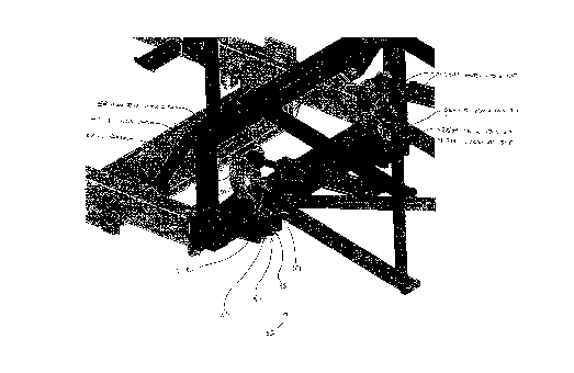
Figure 4 is a side view of the boom lift mechanism;
Figure 5 is a partial view of the boom lift mechanism;
Figure 6 is a view of the suspension link;
Figure 7 illustrates the effects of downward vertical forces;
Figure 8 illustrates the effects of upward vertical forces;
Figure 9 is a partial view of the suspension link mounted on the sprayer
frame;
Figure 10 is an exploded view of the system.
Detailed Description
This invention will be described in terms of a suspended boom sprayer, but
could
also be incorporated in conjunction with other implements such as swathers or
loaders.
Figure 1 illustrates a common suspended boom sprayer in field position as
known
in the art. The sprayer includes a tank 10 supported by frame 12. The tank

CA 02278073 1999-07-16
-3-
generally contains herbicide for distribution over a field. The sprayer can be
self
propelled or pulled by a prime mover such as a tractor as illustrated in the
Figures.
The tank could also be skid or truck mounted. The sprayer also incorporates
boom
sections. In the preferred embodiment, the sprayer has a center boom section
14,
left boom section 16 and right boom section 18. The left and right boom
sections
are pivotally connected to the boom frame 15 at brackets 20. The boom sections
include spray nozzles (not shown) located at regular intervals along the boom
sections. Chemical supply lines carry the chemical from the tank to the
nozzles
for distribution over the ground as the sprayer travels over a field.
The sprayer may include optional windscreens 22 or other such drift control
means. The sprayer is equipped to allow the boom sections to fold from field
position to transport position as seen in Figure 2. In transport, the center
section
is lifted up and towards the rear sprayer frame 13 and the left and right boom
sections fold about a generally vertical axis at brackets 20 inwardly.
The boom lift mechanism 30 consists of a pair of spaced apart parallel link
systems 32 as seen in Figure 4. Each system includes a lower parallel link 34
pivotally connected to the rear sprayer frame 13 at pin 40 and to the rear of
the
boom frame 15 at pin 41. Each upper parallel link 36 is connected similarly at
pins 42 and 43. The boom lift mechanism 30 is hydraulically operated via lift
cylinders 38. The rod end 39 of each lift cylinder is pivotally connected to
piw44
on the rear sprayer frame. The cylinder end is connected to pin 45. Suspension
link 50 pivots about pins 40 and 44. All pin connections are secured
accordingly
by common bolt and lock nut assemblies.
The suspension link is illustrated in Figure 6. The link consists of two link
plates
60 and 61, mounting plate 62 for mounting to the rear sprayer frame, flat
spacer

CA 02278073 1999-07-16
-4-
63 and bushings 64.
When the lift cylinders are extended, the parallel link system pivots about
the pins
to lift the boom frame and boom sections. Left and right boom sections then
pivot
about brackets 20 to fold inwardly toward the cart frame.
Also provided on the sprayer is a suspension assembly 52 to minimize vertical
movement ofthe boom sections. First and second bushings 51 and 53 are inserted
between each suspension link 50 and the sprayer frame 13. The bushings are
preferably polyurethane (or some other resilient means) and approximately 1"
thick. Alternatively, a single 2" bushing could be used. A third bushing 55,
preferably polyurethane and 1/2" thick, is located to the outside ofthe
suspension
assembly 52. The bushings 51, 53 and 55 are secured by the presence of a
washer
57, bolt 58 and lock nut 59. First and second suspensions are located between
the
cart frame and each suspension link.
As the sprayer travels over the field, vertical movements of the sprayer cart
are
translated into the suspended boom assembly. Downward vertical boom
movement causes the lift cylinder to push on the suspension link towards the
front
of the cart. The suspension link then pivots about the common pin 40 with the
lower parallel link and compresses bushings 51 and 53. Upward vertical boom
movement causes the lift cylinder to pull on the suspension links towards the
back
of the cart. The suspension link pivots about pin 40 with the lower parallel
links
and compresses bushing 55.
Numerous alternative embodiments will be apparent to persons skilled in the
art
without departing from the spirit and scope of the invention as defined in the
claims attached.

Dessin représentatif
Une figure unique qui représente un dessin illustrant l'invention.
États administratifs

2024-08-01 : Dans le cadre de la transition vers les Brevets de nouvelle génération (BNG), la base de données sur les brevets canadiens (BDBC) contient désormais un Historique d'événement plus détaillé, qui reproduit le Journal des événements de notre nouvelle solution interne.

Veuillez noter que les événements débutant par « Inactive : » se réfèrent à des événements qui ne sont plus utilisés dans notre nouvelle solution interne.

Pour une meilleure compréhension de l'état de la demande ou brevet qui figure sur cette page, la rubrique Mise en garde , et les descriptions de Brevet , Historique d'événement , Taxes périodiques et Historique des paiements devraient être consultées.

Historique d'événement

Description Date
Inactive : CIB désactivée 2011-07-29
Inactive : CIB en 1re position 2010-02-05
Inactive : CIB attribuée 2010-02-05
Inactive : CIB expirée 2010-01-01
Inactive : CIB de MCD 2006-03-12
Inactive : Morte - Aucune rép. à lettre officielle 2001-10-18
Demande non rétablie avant l'échéance 2001-10-18
Réputée abandonnée - omission de répondre à un avis sur les taxes pour le maintien en état 2001-07-16
Demande publiée (accessible au public) 2001-01-16
Inactive : Page couverture publiée 2001-01-15
Inactive : Renseign. sur l'état - Complets dès date d'ent. journ. 2000-11-27
Inactive : Abandon. - Aucune rép. à lettre officielle 2000-10-18
Inactive : CIB en 1re position 1999-10-14
Inactive : CIB attribuée 1999-10-14
Inactive : Lettre de courtoisie - Preuve 1999-08-31
Inactive : Certificat de dépôt - Sans RE (Anglais) 1999-08-24
Demande reçue - nationale ordinaire 1999-08-23

Historique d'abandonnement

Date d'abandonnement Raison Date de rétablissement
2001-07-16

Historique des taxes

Type de taxes Anniversaire Échéance Date payée
Taxe pour le dépôt - générale 1999-07-16
Titulaires au dossier

Les titulaires actuels et antérieures au dossier sont affichés en ordre alphabétique.

Titulaires actuels au dossier
FLEXI-COIL LTD.
Titulaires antérieures au dossier
DENNIS GEORGE THOMPSON
DENNIS W. CHAHLEY
Les propriétaires antérieurs qui ne figurent pas dans la liste des « Propriétaires au dossier » apparaîtront dans d'autres documents au dossier.
Documents

Pour visionner les fichiers sélectionnés, entrer le code reCAPTCHA :


Pour visualiser une image, cliquer sur un lien dans la colonne description du document (Temporairement non-disponible). Pour télécharger l'image (les images), cliquer l'une ou plusieurs cases à cocher dans la première colonne et ensuite cliquer sur le bouton "Télécharger sélection en format PDF (archive Zip)" ou le bouton "Télécharger sélection (en un fichier PDF fusionné)".

Liste des documents de brevet publiés et non publiés sur la BDBC .

Si vous avez des difficultés à accéder au contenu, veuillez communiquer avec le Centre de services à la clientèle au 1-866-997-1936, ou envoyer un courriel au Centre de service à la clientèle de l'OPIC.

({010=Tous les documents, 020=Au moment du dépôt, 030=Au moment de la mise à la disponibilité du public, 040=À la délivrance, 050=Examen, 060=Correspondance reçue, 070=Divers, 080=Correspondance envoyée, 090=Paiement})


Description du
Document 
Date
(aaaa-mm-jj) 
Nombre de pages   Taille de l'image (Ko) 
Abrégé 2001-01-15 1 2
Dessins 1999-07-15 9 1 005
Revendications 1999-07-15 1 26
Description 1999-07-15 4 177
Dessin représentatif 2001-01-02 1 48
Certificat de dépôt (anglais) 1999-08-23 1 175
Demande de preuve ou de transfert manquant 2000-07-17 1 110
Courtoisie - Lettre d'abandon (lettre du bureau) 2000-11-21 1 171
Rappel de taxe de maintien due 2001-03-18 1 112
Courtoisie - Lettre d'abandon (taxe de maintien en état) 2001-08-12 1 185
Correspondance 1999-08-23 1 14